EP0186840A2 - Boîtier d'articulation pour levier de changement de vitesse de véhicule avec verrouillage de manche arrière - Google Patents
Boîtier d'articulation pour levier de changement de vitesse de véhicule avec verrouillage de manche arrière Download PDFInfo
- Publication number
- EP0186840A2 EP0186840A2 EP85116018A EP85116018A EP0186840A2 EP 0186840 A2 EP0186840 A2 EP 0186840A2 EP 85116018 A EP85116018 A EP 85116018A EP 85116018 A EP85116018 A EP 85116018A EP 0186840 A2 EP0186840 A2 EP 0186840A2
- Authority
- EP
- European Patent Office
- Prior art keywords
- ring
- stop
- housing
- bearing housing
- gearshift lever
- Prior art date
- Legal status (The legal status is an assumption and is not a legal conclusion. Google has not performed a legal analysis and makes no representation as to the accuracy of the status listed.)
- Granted
Links
Images

Classifications
-
- F—MECHANICAL ENGINEERING; LIGHTING; HEATING; WEAPONS; BLASTING
- F16—ENGINEERING ELEMENTS AND UNITS; GENERAL MEASURES FOR PRODUCING AND MAINTAINING EFFECTIVE FUNCTIONING OF MACHINES OR INSTALLATIONS; THERMAL INSULATION IN GENERAL
- F16H—GEARING
- F16H61/00—Control functions within control units of change-speed- or reversing-gearings for conveying rotary motion ; Control of exclusively fluid gearing, friction gearing, gearings with endless flexible members or other particular types of gearing
- F16H61/18—Preventing unintentional or unsafe shift, e.g. preventing manual shift from highest gear to reverse gear
-
- F—MECHANICAL ENGINEERING; LIGHTING; HEATING; WEAPONS; BLASTING
- F16—ENGINEERING ELEMENTS AND UNITS; GENERAL MEASURES FOR PRODUCING AND MAINTAINING EFFECTIVE FUNCTIONING OF MACHINES OR INSTALLATIONS; THERMAL INSULATION IN GENERAL
- F16H—GEARING
- F16H59/00—Control inputs to control units of change-speed- or reversing-gearings for conveying rotary motion
- F16H59/02—Selector apparatus
- F16H59/04—Ratio selector apparatus
- F16H2059/048—Ratio selector apparatus with means for unlocking select or shift movement to allow access to reverse gear position
-
- Y—GENERAL TAGGING OF NEW TECHNOLOGICAL DEVELOPMENTS; GENERAL TAGGING OF CROSS-SECTIONAL TECHNOLOGIES SPANNING OVER SEVERAL SECTIONS OF THE IPC; TECHNICAL SUBJECTS COVERED BY FORMER USPC CROSS-REFERENCE ART COLLECTIONS [XRACs] AND DIGESTS
- Y10—TECHNICAL SUBJECTS COVERED BY FORMER USPC
- Y10T—TECHNICAL SUBJECTS COVERED BY FORMER US CLASSIFICATION
- Y10T74/00—Machine element or mechanism
- Y10T74/20—Control lever and linkage systems
- Y10T74/20012—Multiple controlled elements
- Y10T74/20018—Transmission control
- Y10T74/20085—Restriction of shift, gear selection, or gear engagement
- Y10T74/20091—Prevention of reverse shift
-
- Y—GENERAL TAGGING OF NEW TECHNOLOGICAL DEVELOPMENTS; GENERAL TAGGING OF CROSS-SECTIONAL TECHNOLOGIES SPANNING OVER SEVERAL SECTIONS OF THE IPC; TECHNICAL SUBJECTS COVERED BY FORMER USPC CROSS-REFERENCE ART COLLECTIONS [XRACs] AND DIGESTS
- Y10—TECHNICAL SUBJECTS COVERED BY FORMER USPC
- Y10T—TECHNICAL SUBJECTS COVERED BY FORMER US CLASSIFICATION
- Y10T74/00—Machine element or mechanism
- Y10T74/20—Control lever and linkage systems
- Y10T74/20012—Multiple controlled elements
- Y10T74/20018—Transmission control
- Y10T74/20085—Restriction of shift, gear selection, or gear engagement
- Y10T74/20122—Spherical restrictor
Definitions
- the invention relates to a bearing housing for motor vehicle gearshift lever with reverse gear lock, which has a stop for a locking member of the gearshift lever, which is movable away from the stop for engaging the reverse gear.
- Gear shift levers for motor vehicles, in particular passenger vehicles, with a reverse gear lock, which is intended to prevent the unintentional engagement of the reverse gear are known.
- they have a locking element which interacts with a stop on the bearing housing in which the gearshift lever is pivotally mounted such that the gearshift lever can only be pivoted into the position required for engaging the reverse gear if the locking element has been removed from the stop has been moved away, which happens with the help of an actuator provided on the gearshift lever.
- the stop for the locking member of the gear shift lever is formed on the bearing housing itself (DE-U 83 22 840).
- the invention has for its object to provide a bearing housing for motor vehicle gearshift lever with reverse gear lock of the type mentioned, which can be easily provided with the stop for the locking member of the gearshift lever.
- the stop for the locking member of the gearshift lever is provided on a separate ring which can be plugged on or plugged into or into a sleeve-shaped housing extension penetrated by the gearshift lever and can be locked with the housing extension, the ring preferably being consists of plastic, while the housing attachment is made of metal, as is the rest of the bearing housing.
- the bearing housing according to the invention for motor vehicle gearshift levers with a reverse gear lock can therefore be adapted without difficulty to a wide variety of gearshift lever shifting schemes.
- the ring provided with the stop for the locking member of the gear shift lever can be easily made of plastic and is also easy to assemble. When manufacturing from plastic there is also the advantage that a low weight is ensured and the ring can dampen noise.
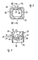
- the gearshift lever 1 is provided with a spherical section 2 and is pivotably mounted by means of the same via a bearing shell 3 in a bearing housing 4, so that it can be pivoted both in the plane of the drawing in FIG to change the gear change transmission of a motor vehicle in its various gears.
- the bearing shell 3 consists of several segments, which are pressed by a helical compression spring 6 against the spherical section 2 of the gear lever 1.
- a sealing bellows 7 is provided between the lower end 5 of the gearshift lever 1 and the bearing housing 4, and a further sealing bellows 8 is provided between the shaft of the gearshift lever 1 projecting upward from the bearing housing 4 and the bearing housing 4.
- the gearshift lever 1 is provided with a locking member 9 which interacts with a stop 10 of the bearing housing 4 and must first be moved away from the latter before the reverse gear can be engaged.
- the gearshift lever 1 has an actuating member which is connected via a tension member 11 running within the hollow gearshift lever 1 to a pin 12 which is axially displaceably arranged in the gearshift lever 1 and which is directed by a helical compression spring 13 towards the lower end 5 of the gearshift lever 1 Position is loaded in which the reverse gear lock is effective, i.e. the reverse gear cannot be engaged.
- the pin 12 is provided with a cross pin 14, which protrudes laterally at one end from the gearshift lever 1 in order to cooperate with the stop 10 of the bearing housing 4 and thus form the actual locking member 9.
- the stop 10 of the bearing housing 4 is provided on a separate ring 15 made of plastic, which is pushed or plugged onto a sleeve-shaped housing attachment 16 and locked with the housing attachment 16, which surrounds the bearing shell 3 and, like the rest of the bearing housing 4, is made of metal.
- the ring 15 rests with a shoulder 17 on the end face of the housing attachment 16 and is held in this position by latching tongues 18 on the housing attachment 16, which engage with their free ends 19 in corresponding locking holes 20 of the housing attachment 16.
- the locking tongues 18 of the ring 15 are integrally formed with the same, each extend in an opening 21 of the ring 15 in the longitudinal direction thereof on the shoulder 17 and can spring laterally, so that the free when plugging or sliding the ring 15 onto the housing approach 16 trailing ends 19 of the latching tongues 18 can then first radially deflect into the openings 21 of the ring 15 and then spring back again into the starting position in order to enter the latching holes 20 of the housing extension 16 and to hold the ring 15 thereon, as shown in FIG. 1 .
- the ring 15 and the housing extension 16 are cylindrical.
- the locking tongues 18 and the locking holes 20 are evenly distributed in the circumferential direction of the ring 15 and the housing projection 16.
- the ring 15 is provided with a projection 22 projecting away from the housing extension 16, on which the stop 10 for the locking member 9 of the gear shift lever 1 is provided.
- the projection 22 is designed as a sleeve 23 coaxial with the ring 15, which has a recess 24 for receiving the locking member 9.
- the bottom 25 is provided with a step 26 which forms the stop 10 for the locking member 9 of the gear shift lever 1.
- the gear shift lever 1 must be pivoted clockwise from the position shown in FIG. 1, which is only possible when the reverse gear lock has been released.
- the aforementioned actuation of the gear lever 1 is moved in order to move the pin 12 against the action of the helical compression spring 13 in the longitudinal direction of the gear lever 1 via the tension member 11 and to move the cross bolt 14 accordingly, so that the locking member 9 is raised above the step 26 is and leaves the stop 10.
- the bottom 25 of the recess 24 of the sleeve-shaped projection 22 of the ring 15 is curved on both sides of the step 26, so that the cross bolt 14 can slide thereon with the end protruding from the gearshift lever 1.
- the ring 15 and the housing extension 16 are cylindrical, but they can also be have other cross-sectional shape, such as an elliptical, square or rectangular cross-section.
- the ring 15 and the housing attachment 16 can also be designed such that the ring 15 can be inserted or inserted into the housing attachment 16 in order to then latch with the housing attachment 16.
- the projection 22 is sleeve-shaped, but it can also be formed, for example, only as a wall which extends on that side of the gearshift lever 1 on which the cross pin 14 protrudes therefrom, and on which the Step 26 is formed on the side of the wall facing away from the housing extension 16.
- the locking tongues 18 of the ring 15 and the locking holes 20 of the housing attachment 16 do not necessarily have to be uniformly distributed in the circumferential direction of the bearing housing 4, but can also be arranged in a different distribution, just as it is also possible in principle, the locking tongues 18 on the housing attachment 16 and the Provide locking holes 20 on the ring 15.
Landscapes
- Engineering & Computer Science (AREA)
- General Engineering & Computer Science (AREA)
- Mechanical Engineering (AREA)
- Arrangement Or Mounting Of Control Devices For Change-Speed Gearing (AREA)
- Gear-Shifting Mechanisms (AREA)
- Mechanical Control Devices (AREA)
- Control Of Transmission Device (AREA)
Priority Applications (1)
| Application Number | Priority Date | Filing Date | Title |
|---|---|---|---|
| AT85116018T ATE35653T1 (de) | 1984-12-18 | 1985-12-17 | Lagergehaeuse fuer kraftfahrzeug-gangschalthebel mit rueckwaertsgangsperre. |
Applications Claiming Priority (2)
| Application Number | Priority Date | Filing Date | Title |
|---|---|---|---|
| DE8437043U | 1984-12-18 | ||
| DE19848437043U DE8437043U1 (de) | 1984-12-18 | 1984-12-18 | Lagergehaeuse fuer kraftfahrzeug-gangschalthebel mit rueckwaertsgangsperre |
Publications (3)
| Publication Number | Publication Date |
|---|---|
| EP0186840A2 true EP0186840A2 (fr) | 1986-07-09 |
| EP0186840A3 EP0186840A3 (en) | 1987-06-10 |
| EP0186840B1 EP0186840B1 (fr) | 1988-07-13 |
Family
ID=6773886
Family Applications (1)
| Application Number | Title | Priority Date | Filing Date |
|---|---|---|---|
| EP85116018A Expired EP0186840B1 (fr) | 1984-12-18 | 1985-12-17 | Boîtier d'articulation pour levier de changement de vitesse de véhicule avec verrouillage de manche arrière |
Country Status (6)
| Country | Link |
|---|---|
| US (1) | US4646585A (fr) |
| EP (1) | EP0186840B1 (fr) |
| JP (1) | JPH0749249B2 (fr) |
| AT (1) | ATE35653T1 (fr) |
| DE (1) | DE8437043U1 (fr) |
| ES (1) | ES291110Y (fr) |
Families Citing this family (16)
| Publication number | Priority date | Publication date | Assignee | Title |
|---|---|---|---|---|
| JPH069939B2 (ja) * | 1986-11-29 | 1994-02-09 | いすゞ自動車株式会社 | 自動変速機のシフトレバ装置 |
| US4960009A (en) * | 1988-06-02 | 1990-10-02 | Dana Corporation | Noise and vibration damper for a transmission shift lever |
| CA1328667C (fr) * | 1988-06-02 | 1994-04-19 | Donald C. Schultz | Amortisseur anti-bruit et anti-vibration pour levier de vitesses |
| US4916966A (en) * | 1988-11-04 | 1990-04-17 | Dawlen Corporation | Transmission shift vibration damper |
| JP2501348Y2 (ja) * | 1990-07-26 | 1996-06-19 | 株式会社東海理化電機製作所 | 車両の自動変速機用シフトレバ―装置 |
| DE4127730A1 (de) * | 1991-08-22 | 1993-03-04 | Ford Werke Ag | Schalthebellagerung fuer getriebe von kraftfahrzeugen |
| US5499919A (en) * | 1993-10-04 | 1996-03-19 | The United States Of America As Represented By The Secretary Of The Navy | Aircraft control lever simulator |
| JPH08189557A (ja) * | 1995-01-09 | 1996-07-23 | Atsumi Tec:Kk | チェンジレバーの支持構造 |
| IT1276412B1 (it) * | 1995-06-06 | 1997-10-31 | Paolo Paparoni | Perfezionamento ai dispositivi inibitori di innesto involontario di retromarcia, per comandi esterni di cambi di velocita' di autoveicoli. |
| BR9702671A (pt) * | 1997-08-13 | 1998-06-02 | Paolo Paparoni | Comando externo de cãmbio automotivo com inibidor de engate involuntário de marcha a ré |
| GB2347181A (en) * | 1999-02-23 | 2000-08-30 | Draftex Ind Ltd | Releasably preventing movement of a gear lever into reverse gear |
| JP2005324756A (ja) * | 2004-05-17 | 2005-11-24 | Delta Kogyo Co Ltd | リバースミスシフト防止構造 |
| JP4593167B2 (ja) * | 2004-05-18 | 2010-12-08 | デルタ工業株式会社 | リバースミスシフト防止構造 |
| JP4593166B2 (ja) * | 2004-05-18 | 2010-12-08 | デルタ工業株式会社 | リバースミスシフト防止構造 |
| DE102010021559A1 (de) | 2010-05-26 | 2011-12-01 | Gm Global Technology Operations Llc (N.D.Ges.D. Staates Delaware) | Gangschalthebel mit Dämpfungsvorrichtung eines Fahrzeugs |
| CN103758992B (zh) * | 2014-02-18 | 2016-03-16 | 上海南慧电缆有限公司 | 能吸震的汽车手排变速操纵器 |
Family Cites Families (7)
| Publication number | Priority date | Publication date | Assignee | Title |
|---|---|---|---|---|
| US1241414A (en) * | 1917-05-10 | 1917-09-25 | Int Motor Co | Gear-shifting mechanism. |
| US2876485A (en) * | 1954-12-03 | 1959-03-10 | Gen Tire & Rubber Co | Interlocking assembly |
| US3597992A (en) * | 1969-08-06 | 1971-08-10 | Deano Dyno Soars Inc | Reverse gear lockout mechanism |
| DE2003874C3 (de) * | 1970-01-29 | 1974-02-07 | Daimler-Benz Ag, 7000 Stuttgart | Mit einem Schaltrohr gelenkig verbundener Handschalthebel, insbesondere Mittelschalthebel, für das Wechselgetriebe von Kraftfahrzeugen |
| US4118999A (en) * | 1976-10-15 | 1978-10-10 | Bieber William J | Automatic transmission shifter |
| JPS59200321A (ja) * | 1983-04-26 | 1984-11-13 | Nissan Shatai Co Ltd | 自動変速機操作用シフトレバ−の位置決め装置 |
| DE8322840U1 (de) * | 1983-08-08 | 1983-12-22 | Fhs Stahlverformung Gmbh, 5860 Iserlohn | Gangschalthebel fuer kraftfahrzeuge |
-
1984
- 1984-12-18 DE DE19848437043U patent/DE8437043U1/de not_active Expired
-
1985
- 1985-12-16 US US06/809,478 patent/US4646585A/en not_active Expired - Fee Related
- 1985-12-17 EP EP85116018A patent/EP0186840B1/fr not_active Expired
- 1985-12-17 AT AT85116018T patent/ATE35653T1/de not_active IP Right Cessation
- 1985-12-18 JP JP60285369A patent/JPH0749249B2/ja not_active Expired - Fee Related
- 1985-12-18 ES ES1985291110U patent/ES291110Y/es not_active Expired
Also Published As
| Publication number | Publication date |
|---|---|
| EP0186840A3 (en) | 1987-06-10 |
| DE8437043U1 (de) | 1985-04-11 |
| EP0186840B1 (fr) | 1988-07-13 |
| ES291110Y (es) | 1987-06-16 |
| ES291110U (es) | 1986-10-16 |
| JPS61196824A (ja) | 1986-09-01 |
| ATE35653T1 (de) | 1988-07-15 |
| JPH0749249B2 (ja) | 1995-05-31 |
| US4646585A (en) | 1987-03-03 |
Similar Documents
| Publication | Publication Date | Title |
|---|---|---|
| EP0186840B1 (fr) | Boîtier d'articulation pour levier de changement de vitesse de véhicule avec verrouillage de manche arrière | |
| DE10144063B4 (de) | Parksperre für ein Automatikgetriebe eines Kraftfahrzeuges | |
| DE2611558A1 (de) | Kupplungsdrucklager | |
| DE3732674A1 (de) | Innen-handgriff fuer ein kraftfahrzeug | |
| DE4112132B4 (de) | Hebelwerk | |
| DE69123335T2 (de) | Einrichtung für das Justieren der Länge einer Stange, insbesondere eine Stange für die Operation eines Fahrzeugschlosses | |
| DE102018128203A1 (de) | Elektrisches Steckverbinderteil und elektrisches Steckverbindungssystem mit Verriegelung | |
| DE9311243U1 (de) | Drehverschluß | |
| DE102017108335A1 (de) | Befestigungsanordnung und ein entsprechendes Schaltschrankgehäuse | |
| DE69111749T2 (de) | Steuerseilselbsteinstellvorrichtung. | |
| EP0703520B1 (fr) | Levier de changement de vitesses pour véhicules | |
| DE102020213568A1 (de) | Verbindung zwischen einem Schalthebel und einer Verbindungsstange einer Parksperre eines Kraftfahrzeugs | |
| DE102004031940B3 (de) | Schalt-/Wählhebel eines Kraftfahrzeuggetriebes | |
| DE10017247C1 (de) | Handschaltung für ein Kraftfahrzeug | |
| DE4204630C2 (de) | Kugelraste für die Lagefixierung eines beweglichen Stellelementes | |
| DE69623270T2 (de) | Kupplung für endstücke von bowdenzügen | |
| DE3236531A1 (de) | Drehschalter, insbesondere fuer kraftfahrzeuge | |
| EP1654472A1 (fr) | Element d'encliquetage | |
| DE69401540T2 (de) | Lenkradschloss für Kraftfahrzeuge | |
| DE2604325B2 (de) | Wischvorrichtung für Scheiben von Kraftfahrzeugen | |
| DE9313484U1 (de) | Betätigungszug für die Betätigung von Einrichtungen insbesondere in Fahrzeugen | |
| DE2641340C3 (de) | Drehverbindung als Teil eines Türklinken-Betätigungsmechanismus und einer hierin drehbar angeordneten Metallstange | |
| DE8705317U1 (de) | Vorrichtung zur Verriegelung einer Kopfstütze eines Fahrzeugsitzes | |
| DE102013219943A1 (de) | Schaltanordnung für ein Kraftfahrzeug-Zahnräderwechselgetriebe | |
| DE19706560A1 (de) | Ringschloß zum Sichern von beweglichen Gegenständen, insbesondere Zweirädern oder dergleichen Fahrzeuge |
Legal Events
| Date | Code | Title | Description |
|---|---|---|---|
| PUAI | Public reference made under article 153(3) epc to a published international application that has entered the european phase |
Free format text: ORIGINAL CODE: 0009012 |
|
| AK | Designated contracting states |
Kind code of ref document: A2 Designated state(s): AT BE CH FR GB IT LI NL SE |
|
| PUAL | Search report despatched |
Free format text: ORIGINAL CODE: 0009013 |
|
| AK | Designated contracting states |
Kind code of ref document: A3 Designated state(s): AT BE CH FR GB IT LI NL SE |
|
| 17P | Request for examination filed |
Effective date: 19870521 |
|
| 17Q | First examination report despatched |
Effective date: 19871221 |
|
| GRAA | (expected) grant |
Free format text: ORIGINAL CODE: 0009210 |
|
| AK | Designated contracting states |
Kind code of ref document: B1 Designated state(s): AT BE CH FR GB IT LI NL SE |
|
| REF | Corresponds to: |
Ref document number: 35653 Country of ref document: AT Date of ref document: 19880715 Kind code of ref document: T |
|
| GBT | Gb: translation of ep patent filed (gb section 77(6)(a)/1977) | ||
| ET | Fr: translation filed | ||
| ITF | It: translation for a ep patent filed | ||
| PLBE | No opposition filed within time limit |
Free format text: ORIGINAL CODE: 0009261 |
|
| STAA | Information on the status of an ep patent application or granted ep patent |
Free format text: STATUS: NO OPPOSITION FILED WITHIN TIME LIMIT |
|
| 26N | No opposition filed | ||
| PGFP | Annual fee paid to national office [announced via postgrant information from national office to epo] |
Ref country code: GB Payment date: 19941215 Year of fee payment: 10 |
|
| PGFP | Annual fee paid to national office [announced via postgrant information from national office to epo] |
Ref country code: SE Payment date: 19941221 Year of fee payment: 10 |
|
| PGFP | Annual fee paid to national office [announced via postgrant information from national office to epo] |
Ref country code: FR Payment date: 19941223 Year of fee payment: 10 |
|
| PGFP | Annual fee paid to national office [announced via postgrant information from national office to epo] |
Ref country code: AT Payment date: 19941227 Year of fee payment: 10 |
|
| ITTA | It: last paid annual fee | ||
| PGFP | Annual fee paid to national office [announced via postgrant information from national office to epo] |
Ref country code: NL Payment date: 19941231 Year of fee payment: 10 |
|
| PGFP | Annual fee paid to national office [announced via postgrant information from national office to epo] |
Ref country code: CH Payment date: 19950110 Year of fee payment: 10 |
|
| PGFP | Annual fee paid to national office [announced via postgrant information from national office to epo] |
Ref country code: BE Payment date: 19950118 Year of fee payment: 10 |
|
| EAL | Se: european patent in force in sweden |
Ref document number: 85116018.4 |
|
| PG25 | Lapsed in a contracting state [announced via postgrant information from national office to epo] |
Ref country code: GB Effective date: 19951217 Ref country code: AT Effective date: 19951217 |
|
| PG25 | Lapsed in a contracting state [announced via postgrant information from national office to epo] |
Ref country code: SE Effective date: 19951218 |
|
| PG25 | Lapsed in a contracting state [announced via postgrant information from national office to epo] |
Ref country code: LI Effective date: 19951231 Ref country code: CH Effective date: 19951231 Ref country code: BE Effective date: 19951231 |
|
| BERE | Be: lapsed |
Owner name: FHS STAHLVERFORMUNG G.M.B.H. Effective date: 19951231 |
|
| PG25 | Lapsed in a contracting state [announced via postgrant information from national office to epo] |
Ref country code: NL Effective date: 19960701 |
|
| GBPC | Gb: european patent ceased through non-payment of renewal fee |
Effective date: 19951217 |
|
| REG | Reference to a national code |
Ref country code: CH Ref legal event code: PL |
|
| PG25 | Lapsed in a contracting state [announced via postgrant information from national office to epo] |
Ref country code: FR Effective date: 19960830 |
|
| NLV4 | Nl: lapsed or anulled due to non-payment of the annual fee |
Effective date: 19960701 |
|
| REG | Reference to a national code |
Ref country code: FR Ref legal event code: ST |