EP0186879B1 - Appareil de radiation à haute intensité - Google Patents
Appareil de radiation à haute intensité Download PDFInfo
- Publication number
- EP0186879B1 EP0186879B1 EP85116346A EP85116346A EP0186879B1 EP 0186879 B1 EP0186879 B1 EP 0186879B1 EP 85116346 A EP85116346 A EP 85116346A EP 85116346 A EP85116346 A EP 85116346A EP 0186879 B1 EP0186879 B1 EP 0186879B1
- Authority
- EP
- European Patent Office
- Prior art keywords
- liquid
- chamber
- electrode
- arc
- arc chamber
- Prior art date
- Legal status (The legal status is an assumption and is not a legal conclusion. Google has not performed a legal analysis and makes no representation as to the accuracy of the status listed.)
- Expired
Links
- 230000005855 radiation Effects 0.000 title claims description 8
- 239000007788 liquid Substances 0.000 claims description 59
- 230000007423 decrease Effects 0.000 claims description 5
- 238000002347 injection Methods 0.000 claims description 5
- 239000007924 injection Substances 0.000 claims description 5
- 238000001816 cooling Methods 0.000 claims description 4
- 238000010891 electric arc Methods 0.000 claims description 3
- 239000007789 gas Substances 0.000 claims 7
- 239000011261 inert gas Substances 0.000 claims 2
- 230000037361 pathway Effects 0.000 claims 2
- 238000003260 vortexing Methods 0.000 description 8
- 238000000926 separation method Methods 0.000 description 7
- XLYOFNOQVPJJNP-UHFFFAOYSA-N water Substances O XLYOFNOQVPJJNP-UHFFFAOYSA-N 0.000 description 7
- 230000003993 interaction Effects 0.000 description 3
- 239000002245 particle Substances 0.000 description 3
- 239000002826 coolant Substances 0.000 description 2
- 238000000034 method Methods 0.000 description 2
- 239000000203 mixture Substances 0.000 description 2
- 239000010453 quartz Substances 0.000 description 2
- VYPSYNLAJGMNEJ-UHFFFAOYSA-N silicon dioxide Inorganic materials O=[Si]=O VYPSYNLAJGMNEJ-UHFFFAOYSA-N 0.000 description 2
- 230000007704 transition Effects 0.000 description 2
- 241000755266 Kathetostoma giganteum Species 0.000 description 1
- 230000002411 adverse Effects 0.000 description 1
- 230000003247 decreasing effect Effects 0.000 description 1
- 238000006073 displacement reaction Methods 0.000 description 1
- 239000000463 material Substances 0.000 description 1
- 230000002093 peripheral effect Effects 0.000 description 1
- 230000000717 retained effect Effects 0.000 description 1
- 230000035939 shock Effects 0.000 description 1
- WFKWXMTUELFFGS-UHFFFAOYSA-N tungsten Chemical compound [W] WFKWXMTUELFFGS-UHFFFAOYSA-N 0.000 description 1
- 229910052721 tungsten Inorganic materials 0.000 description 1
- 239000010937 tungsten Substances 0.000 description 1
Images
Classifications
-
- H—ELECTRICITY
- H01—ELECTRIC ELEMENTS
- H01J—ELECTRIC DISCHARGE TUBES OR DISCHARGE LAMPS
- H01J61/00—Gas-discharge or vapour-discharge lamps
- H01J61/02—Details
- H01J61/24—Means for obtaining or maintaining the desired pressure within the vessel
- H01J61/28—Means for producing, introducing, or replenishing gas or vapour during operation of the lamp
-
- H—ELECTRICITY
- H01—ELECTRIC ELEMENTS
- H01J—ELECTRIC DISCHARGE TUBES OR DISCHARGE LAMPS
- H01J61/00—Gas-discharge or vapour-discharge lamps
- H01J61/02—Details
- H01J61/52—Cooling arrangements; Heating arrangements; Means for circulating gas or vapour within the discharge space
Definitions
- This application relates to a high intensity radiation source, and more particularly, to improvements in cooling and electrode life of such high intensity radiation sources.
- the apparatus according to the invention comprises the features indicated in claim 1.
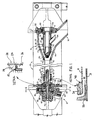
- a high intensity radiation source is generally shown in cutaway at 10 in Figure 1. It comprises a quartz cylindrical arc chamber generally shown at 11, a cathode housing assembly generally shown at 12, an anode housing generally shown at 13 and a discharge or dump area generally shown at 14.
- Support apparatus in the way of a starting circuit and power supply circuit is provided to initiate and maintain the arc discharge across the electrodes until sufficient current is provided to maintain the arc.
- a liquid pump and heat exchanger for the coolant are provided and a gas pump to circulate the gas through the arc chamber will also be required.
- the cathode housing assembly 12 includes a cathode housing 20 which holds a tungsten electrode 21.
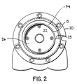
- a nozzle 22 having an outer annulus 15 is mounted to cathode housing 20 (see also Figure 2) using flathead screws 23 and a vortex chamber member 24 is mounted to cathode housing 20 by capscrews 30.
- a ring nut 34 is mounted within cathode mounting bracket 33 and acts to retain vortex chamber member 24 and the rest of the cathode housing assembly 12 in its operating position.
- the configuration of the cathode housing 20 and nozzle 22 when connected thereto is depicted in Figure 2.
- the radial distance between the outer annulus of the nozzle 22 and the annular cavity 74 decreases around the circumference of the cavity 74, the radial distance reflecting cross-sectional area and hence volume. It is preferred that the rate of change of this volume be constant with the angular displacement from the water jet introduction point 25.
- An intermediate chamber 26, communicating with the arc chamber 11, is disposed radially inwardly at the annulus 15.
- a tube insert 40 with an O-ring 41 is sealingly connected to the end of the quartz arc tube 42 and is mounted in vortex chamber 24. Spark arrestors 43 are positioned around the end of arc tube 42.
- the anode housing assembly 13 comprises an anode 44 having an anode tip 50.
- An expansion nozzle 51 encases the anode tip 50 and anode 44.
- the anode 44 and anode tip 50 are connected to expansion nozzle 51 using cap screws 52.
- the anode insert 53 is retained in an anode insert retainer 54 which is connected to anode 44 using cap screws 60.
- An O-ring 61 acts as a seal between the anode 44 and the anode insert retainer 54.
- the expansion nozzle 51 contains no abrupt transition areas. Rather, it smoothly enlarges in a conical configuration until discharge area 14 is reached which dumps the liquid and gas into a dump chamber (not shown) where the liquid and gas separate. Both are pumped through suitable heat exchangers (not shown) and subsequently recirculated.
- An annular cooling chamber 62 is provided to cool the anode 44 and anode inset 53. The liquid is discharged through anode coolant exit nozzle 64 where it is passed to the dump chamber (not shown) for recirculation.
- the anode 44 has a forward portion adjacent the expansion nozzle 51.
- a fin 70 is encountered intermediate the anode. Fin 70 surrounds the circumference of and is part of anode 44. While the forward portion 71 tapers smoothly rearwardly, the rearward portion 72 is concave in shape, both the forward and rearward configurations being for the purposes explained hereafter.
- a forward set of fins 73 is also provided of the same general configuration but smaller than the fin 70 located intermediate the anode 44.
- a high current power supply (not shown) is connected across the electrodes 21, 50.
- a liquid pump and heat exchanger (not shown) provide liquid into the cathode housing 20.
- a stream of liquid cools the interior 75 of electrode 21.
- the cathode housing 20 ( Figure 2) emits a single stream of liquid at liquid injection means 25 on the periphery of the cavity 74 within which nozzle 22 is mounted. As best seen in Figure 2, the water stream travels around the periphery of cavity 74 while the radial distance between the outside of cavity 74 and the outer annulus 15 steadily decreases as the circumferential distance is travelled.
- the annular restriction has an axial gap width and radial length sufficient to provide the required pressure and liquid quantity for the desired radial liquid motion such that macro-turbulence of the liquid is decreased the terms "axial" and "radial” being designated with respect to a longitudinal axis of the arc chamber. It has been found that for a water flow of 22 to 88 l/min (five to twenty U.S. G.P.M.), a suitable gap for a restricting radius of 44,5mm is 0,15 to 0,38mm. Such dimensions also allow liquid irregularities to be removed such that the flow pattern of the liquid into the chamber 26 is smooth to inhibit the abovementioned unnecessary turbulence.
- the separation cylinder 81 is formed so as to take a position substantially coinciding with the equilibrium surface of the water wall formed on the inside periphery of the arc chamber 11.
- the separation cylinder 81 provides physical restraint of the liquid wall surface until the axial flow of the liquid has been established which reduces the interaction of water particles with the vortexing gas.
- Gas is simultaneously introduced through inlet 63 and a vortex of gas is established in cavity 82 by injecting gas tangentially into cavity 82.
- the gas would develop a vortex motion due to the vortexing of the liquid wall in the arc chamber, it is preferable to provide the gas with a tangential velocity.
- the vortexing gas is guided into the peripheral opening between the outside diameter of the cathode 21 and the inside diameter defined by the separation cylinder 81. Again, the physical constraint of the separation cylinder 81 allows for axial flow of the gas to be established thus reducing the possibility of interaction caused by turbulence of the gas and liquid.
- the vortexing gas is guided by the separation cylinder 81 into the arc chamber where it travels to the anode 44.
- the vortexing liquid forms a liquid wall on the inside of the arc tube 42 and flows into the anode housing assembly 13.
- the expansion nozzle 51 of the anode housing assembly 13 tapers smoothly outwardly and has smooth transition areas to minimize turbulence in the liquid and gas flow.
- the liquid and gas mixture is discharged from the discharge area 14 to the dump chamber (not shown).
- fins 70, 73 are positioned to prevent the water from moving towards the anode tip 50.
- the fins 70, 73 will entrap deviant liquid particles and discharge them with the liquid.
- the fins 70, 73 have a forward configuration which will not inhibit the movement of liquid away from the anode tip 50 and a rearward configuration that will inhibit liquid from moving towards the anode tip 50.
- forward and rearward surfaces 71, 72 may take convex and concave configurations, respectively.
- the liquid and gas are recirculated directly or through respective heat exchangers (not shown) to respective inlets in the cathode housing assembly 12.
- the separation cylinder 81 and nozzle 22 could, of course, be separate pieces rather than being machined from a single piece of material as described.
- the anode 44 could use any of several different configurations to prevent liquid particles from travelling towards the anode tip 50.
- the annular restriction depicted, while being satisfactory under the conditions cited, may be adjusted under different operating conditions.
Landscapes
- Plasma Technology (AREA)
- Discharge Lamps And Accessories Thereof (AREA)
Claims (10)
- Appareil (10) de radiation à haute intensité, lequel présente comme suit:
une boîte d'extinction d'arc cylindrique allongée (11), un premier et un second dispositif à électrodes (21, 44) disposés coaxialement à l'intérieur de la boîte d'extinction d'arc, un dispositif pour produire un tourbillonnement de liquide, qui présente une cavité annulaire (74) s'étendant autour de l'un des dispositifs à électrodes, et un dispositif à injection (25) pour injecter du liquide dans la cavité annulaire et de là dans la boîte d'extinction d'arc pour produire un rideau de liquide cylindrique sur la périphérie intérieure de la boîte d'extinction d'arc, de manière à ce qu'une décharge en arc soit déterminée par refroidissement de la périphérie de la décharge en arc, à ce sujet un dispositif (82) étant prévu pour l'injection d'un gaz rare dans l'espace limité au rideau de liquide cylindrique, qui porte un mouvement tourbillonnaire dans la chambre.
caractérisé en ce que:
un espace annulaire (15), qui sépare la cavité annulaire (74) d'une chambre intermédiare (26), qui communique avec la boîte d'extinction d'arc (11), l'espace annulaire (15) présentant une partie, qui s'étend autour d'un (21) des deux dispositifs à électrodes et est disposée à moindre distance d'une des sections opposées à une partie de la chambre tourbillonnaire (24), que délimite ainsi une paroi commune entre la cavité et la chambre intermédiaire, de facon à ce qu'une ouverture circonférentielle se forme, qui est applicable comme dispositif de limitation tourbillonnaire, qui limite le courant de liquide venant de la cavité annulaire (74) dans la chambre intermédiaire (26), de facon que les phénomènes de macroturbulence diminuent dans le liquide avant l'injection dans la boîte d'extinction d'arc (11). - Appareil selon Revendication 1, caractérisé en ce qu'il présente en outre:
une tuyère (22), qui s'étend de la chambre intermédiaire (26) le long de la première électrode (21) et la tuyère présente un diamètre, qui coincide essentiellement avec une surface d'équilibre du rideau de liquide cylindrique, qui limite l'espace intérieur, le dispositif d'injection s'étendant à une distance suffisamment grande, pour permettre la formation d'un mouvement tourbillonnaire du liquide et des gaz, avant même que le gaz entre en contact avec le liquide. - Appareil selon Revendication 2, caractérisé en ce que, l'injection du gaz rare se produit dans la boîte d'extinction d'arc (11) entre un diamètre intérieur de la tuyère (22) et un pourtour de la première électrode (21).
- Appareil selon Revendication 1, caractérisé en outre en ce que:
(a) la cavité annulaire (74) présente une superficie de la section, qui atteint sa taille maximale au niveau du dispositif d'injection de liquide (25) et diminue le long de la circonférence de la cavité annulaire à partir de ce dispositif d'injection. - Appareil selon Revendication 4, caractérisé en ce que, la superficie de la section de la cavité relative à la distance annulaire diminue uniformément autour de la cavité.
- Appareil selon Revendication 1, caractérisé en ce que, par ailleurs:
la première électrode (21) est disposée à l'intérieur du boîtier à électrodes (12) avec une partie de chambre tourbillonnaire (24) un espace annulaire extérieur (15), l'ouverture circonférentielle (27) étant disposée entre l'espace annulaire extérieur (15) et une paroi adjacente de la partie de la chambre tourbillonnaire (24), par laquelle du liquide coule de la chambre tourbillonnaire dans la chambre intermédiaire (26) et de là dans la boîte d'extinction d'arc (11). - Appareil selon Revendication 1, caractérisé en outre en ceci que:
le second dispositif à électrodes (44) présente au moins une nervure (70) disposée dessus, qui est conçue de façon à ce qu'elle forme un passage de courant comparativement sans obstacle en direction du courant de liquide et du courant de gaz de l'intérieur de la boîte d'extinction d'arc (11) et un passage de courant entravé pour le courant de liquide et de gaz, lorsque le courant de liquide et de gaz coulent dans une direction opposée à celle du courant de liquide et de gaz à l'intérieur de la boîte d'extinction d'arc (11). - Appareil selon Revendication 7, caractérisé en ce que, le second dispositif à électrodes (44) présente un premier groupe de nervures comparativement petites, allant de pair (73, 71) près de l'extrémité de l'anode, mais encore un second groupe de nervures allant de pair comparativement plus grandes (70) près de la section médiane de l'anode.
- Appareil selon Revendication 8, caractérisé en par ailleurs en ce que:
une des tuyères d'élargissement communiquant avec un point de rejet de la boîte d'extinction d'arc (11) pour recevoir du courant de liquide et de gaz coulant de celle-ci, cette dernière s'élargit d'une zone de réception située près de la boîte d'extinction d'arc (11) de manière continue jusqu'à la zone de décharge. - Appareil selon Revendication 9, caractérisé en ce, qu'il présente en sus:
(a) une tuyère de décharge (64) disposée près du second dispositif à électrodes (44), qui contrôlable de facon, qu'elle décharge du liquide de la seconde électrode dans la zone de décharge (14).
Applications Claiming Priority (2)
| Application Number | Priority Date | Filing Date | Title |
|---|---|---|---|
| CA000470997A CA1239437A (fr) | 1984-12-24 | 1984-12-24 | Rayonnement haute intensite par une methode et un dispositif a debit liquide turbulent ameliore |
| CA470997 | 1984-12-24 |
Publications (3)
| Publication Number | Publication Date |
|---|---|
| EP0186879A2 EP0186879A2 (fr) | 1986-07-09 |
| EP0186879A3 EP0186879A3 (en) | 1988-11-17 |
| EP0186879B1 true EP0186879B1 (fr) | 1991-07-17 |
Family
ID=4129455
Family Applications (1)
| Application Number | Title | Priority Date | Filing Date |
|---|---|---|---|
| EP85116346A Expired EP0186879B1 (fr) | 1984-12-24 | 1985-12-20 | Appareil de radiation à haute intensité |
Country Status (6)
| Country | Link |
|---|---|
| US (1) | US4700102A (fr) |
| EP (1) | EP0186879B1 (fr) |
| JP (1) | JPS61155999A (fr) |
| CN (1) | CN1007561B (fr) |
| CA (1) | CA1239437A (fr) |
| DE (1) | DE3583497D1 (fr) |
Families Citing this family (18)
| Publication number | Priority date | Publication date | Assignee | Title |
|---|---|---|---|---|
| US4937490A (en) * | 1988-12-19 | 1990-06-26 | Vortek Industries Ltd. | High intensity radiation apparatus and fluid recirculating system therefor |
| US5561735A (en) * | 1994-08-30 | 1996-10-01 | Vortek Industries Ltd. | Rapid thermal processing apparatus and method |
| US5556791A (en) * | 1995-01-03 | 1996-09-17 | Texas Instruments Incorporated | Method of making optically fused semiconductor powder for solar cells |
| GB9506010D0 (en) * | 1995-03-23 | 1995-08-23 | Anderson John E | Electromagnetic energy directing method and apparatus |
| CA2310883A1 (fr) | 1999-06-07 | 2000-12-07 | Norman L. Arrison | Methode et dispositif de fracturation des materiaux cassants par contrainte thermique |
| US6912356B2 (en) * | 1999-06-07 | 2005-06-28 | Diversified Industries Ltd. | Method and apparatus for fracturing brittle materials by thermal stressing |
| US6621199B1 (en) | 2000-01-21 | 2003-09-16 | Vortek Industries Ltd. | High intensity electromagnetic radiation apparatus and method |
| US7445382B2 (en) | 2001-12-26 | 2008-11-04 | Mattson Technology Canada, Inc. | Temperature measurement and heat-treating methods and system |
| AU2003287837A1 (en) | 2002-12-20 | 2004-07-14 | Vortek Industries Ltd | Methods and systems for supporting a workpiece and for heat-treating the workpiece |
| JP5630935B2 (ja) | 2003-12-19 | 2014-11-26 | マトソン テクノロジー、インコーポレイテッド | 工作物の熱誘起運動を抑制する機器及び装置 |
| US7781947B2 (en) | 2004-02-12 | 2010-08-24 | Mattson Technology Canada, Inc. | Apparatus and methods for producing electromagnetic radiation |
| US20050180141A1 (en) * | 2004-02-13 | 2005-08-18 | Norman Arrison | Protection device for high intensity radiation sources |
| JP5967859B2 (ja) | 2006-11-15 | 2016-08-10 | マトソン テクノロジー、インコーポレイテッド | 熱処理中の被加工物を支持するシステムおよび方法 |
| WO2009137940A1 (fr) | 2008-05-16 | 2009-11-19 | Mattson Technology Canada, Inc. | Procédé et appareil de prévention de rupture de pièce ouvrée |
| MX2013010300A (es) | 2011-03-10 | 2014-04-30 | Mesocoat Inc | Equipo y metodo para la fabricacion de productos con revestimiento metalico. |
| US9196760B2 (en) | 2011-04-08 | 2015-11-24 | Ut-Battelle, Llc | Methods for producing complex films, and films produced thereby |
| US9245730B2 (en) | 2012-02-24 | 2016-01-26 | Mattson Technology, Inc. | Apparatus and methods for generating electromagnetic radiation |
| JP2016520711A (ja) | 2013-03-15 | 2016-07-14 | メソコート インコーポレイテッド | 三元系セラミック溶射粉末およびコーティング方法 |
Family Cites Families (5)
| Publication number | Priority date | Publication date | Assignee | Title |
|---|---|---|---|---|
| US3292028A (en) * | 1962-06-20 | 1966-12-13 | Giannini Scient Corp | Gas vortex-stabilized light source |
| US3405305A (en) * | 1964-12-28 | 1968-10-08 | Giannini Scient Corp | Vortex-stabilized radiation source with a hollowed-out electrode |
| US3366815A (en) * | 1965-12-29 | 1968-01-30 | Union Carbide Corp | High pressure arc cooled by a thin film of liquid on the wall of the envelope |
| US4027185A (en) * | 1974-06-13 | 1977-05-31 | Canadian Patents And Development Limited | High intensity radiation source |
| JPS5340274A (en) * | 1976-09-27 | 1978-04-12 | Stanley Electric Co Ltd | Apparatus for controlling vapour pressure in liquiddgrowth furnace for semiconductor |
-
1984
- 1984-12-24 CA CA000470997A patent/CA1239437A/fr not_active Expired
-
1985
- 1985-12-20 DE DE8585116346T patent/DE3583497D1/de not_active Expired - Lifetime
- 1985-12-20 EP EP85116346A patent/EP0186879B1/fr not_active Expired
- 1985-12-23 JP JP60290304A patent/JPS61155999A/ja active Granted
- 1985-12-23 CN CN85109598.4A patent/CN1007561B/zh not_active Expired
- 1985-12-24 US US06/812,977 patent/US4700102A/en not_active Expired - Lifetime
Also Published As
| Publication number | Publication date |
|---|---|
| CA1239437A (fr) | 1988-07-19 |
| US4700102A (en) | 1987-10-13 |
| CN85109598A (zh) | 1986-07-16 |
| JPS61155999A (ja) | 1986-07-15 |
| EP0186879A3 (en) | 1988-11-17 |
| CN1007561B (zh) | 1990-04-11 |
| JPH0568825B2 (fr) | 1993-09-29 |
| EP0186879A2 (fr) | 1986-07-09 |
| DE3583497D1 (de) | 1991-08-22 |
Similar Documents
| Publication | Publication Date | Title |
|---|---|---|
| EP0186879B1 (fr) | Appareil de radiation à haute intensité | |
| EP0748149B1 (fr) | Torche à plasma d'arc comportant un arrangement de buse avec injection d'eau | |
| US4937490A (en) | High intensity radiation apparatus and fluid recirculating system therefor | |
| CA1234689A (fr) | Pistolet au plasma | |
| EP1621052B1 (fr) | Procede et dispositif d'alignement des composants d'une torche au plasma d'arc | |
| JP5086533B2 (ja) | ネジ構造、ネジ構造を有する電極、電極ホルダー、電極/電極ホルダーの組合せからなる装置、プラズマアークトーチ及び電極本体を製造する方法 | |
| US6881919B2 (en) | Powder feed nozzle for laser welding | |
| US4688722A (en) | Nozzle assembly for plasma spray gun | |
| US4587397A (en) | Plasma arc torch | |
| US20080116179A1 (en) | Method and apparatus for alignment of components of a plasma arc torch | |
| US3953705A (en) | Controlled arc gas heater | |
| US4625092A (en) | Plasma arc bulk air heating apparatus | |
| US3390292A (en) | Fluid coolant system for a plasma-jet generator | |
| KR100262800B1 (ko) | 아크플라즈마토치,아크플라즈마 토치용전극 및 이들의 작동방법 | |
| RU2071189C1 (ru) | Плазмотрон | |
| US3686528A (en) | Jet pinched plasma arc lamp and method of forming plasma arc | |
| US4622675A (en) | Forced transport molecular gas laser and method | |
| JP2561289B2 (ja) | 反応性金属の製造装置 | |
| US5635088A (en) | Liquid cooled plasma arc torch system and method for replacing a torch in such system | |
| RU2060130C1 (ru) | Плазмотрон | |
| JPS61116799A (ja) | 軸供給型大出力プラズマジエツト発生装置 | |
| RU2361964C2 (ru) | Способ экономичного плазменного сверхзвукового напыления высокоплотных порошковых покрытий и плазмотрон для его осуществления (варианты) | |
| SU996131A1 (ru) | Горелка дл дуговой сварки в среде защитных газов |
Legal Events
| Date | Code | Title | Description |
|---|---|---|---|
| PUAI | Public reference made under article 153(3) epc to a published international application that has entered the european phase |
Free format text: ORIGINAL CODE: 0009012 |
|
| AK | Designated contracting states |
Kind code of ref document: A2 Designated state(s): DE FR GB NL |
|
| PUAL | Search report despatched |
Free format text: ORIGINAL CODE: 0009013 |
|
| AK | Designated contracting states |
Kind code of ref document: A3 Designated state(s): DE FR GB NL |
|
| 17P | Request for examination filed |
Effective date: 19890222 |
|
| 17Q | First examination report despatched |
Effective date: 19890616 |
|
| GRAA | (expected) grant |
Free format text: ORIGINAL CODE: 0009210 |
|
| AK | Designated contracting states |
Kind code of ref document: B1 Designated state(s): DE FR GB NL |
|
| REF | Corresponds to: |
Ref document number: 3583497 Country of ref document: DE Date of ref document: 19910822 |
|
| ET | Fr: translation filed | ||
| PLBE | No opposition filed within time limit |
Free format text: ORIGINAL CODE: 0009261 |
|
| STAA | Information on the status of an ep patent application or granted ep patent |
Free format text: STATUS: NO OPPOSITION FILED WITHIN TIME LIMIT |
|
| 26N | No opposition filed | ||
| PGFP | Annual fee paid to national office [announced via postgrant information from national office to epo] |
Ref country code: FR Payment date: 19961216 Year of fee payment: 12 |
|
| PGFP | Annual fee paid to national office [announced via postgrant information from national office to epo] |
Ref country code: NL Payment date: 19961231 Year of fee payment: 12 |
|
| PG25 | Lapsed in a contracting state [announced via postgrant information from national office to epo] |
Ref country code: FR Free format text: THE PATENT HAS BEEN ANNULLED BY A DECISION OF A NATIONAL AUTHORITY Effective date: 19971231 |
|
| PG25 | Lapsed in a contracting state [announced via postgrant information from national office to epo] |
Ref country code: NL Free format text: LAPSE BECAUSE OF NON-PAYMENT OF DUE FEES Effective date: 19980701 |
|
| NLV4 | Nl: lapsed or anulled due to non-payment of the annual fee |
Effective date: 19980701 |
|
| REG | Reference to a national code |
Ref country code: FR Ref legal event code: ST |
|
| REG | Reference to a national code |
Ref country code: GB Ref legal event code: IF02 |
|
| PGFP | Annual fee paid to national office [announced via postgrant information from national office to epo] |
Ref country code: DE Payment date: 20041230 Year of fee payment: 20 |
|
| PGFP | Annual fee paid to national office [announced via postgrant information from national office to epo] |
Ref country code: GB Payment date: 20050112 Year of fee payment: 20 |
|
| PG25 | Lapsed in a contracting state [announced via postgrant information from national office to epo] |
Ref country code: GB Free format text: LAPSE BECAUSE OF EXPIRATION OF PROTECTION Effective date: 20051219 |
|
| REG | Reference to a national code |
Ref country code: GB Ref legal event code: PE20 |