EP0186921A1 - Vorrichtung zum Herstellen eines vertikalen Kanals im Boden - Google Patents
Vorrichtung zum Herstellen eines vertikalen Kanals im Boden Download PDFInfo
- Publication number
- EP0186921A1 EP0186921A1 EP85201964A EP85201964A EP0186921A1 EP 0186921 A1 EP0186921 A1 EP 0186921A1 EP 85201964 A EP85201964 A EP 85201964A EP 85201964 A EP85201964 A EP 85201964A EP 0186921 A1 EP0186921 A1 EP 0186921A1
- Authority
- EP
- European Patent Office
- Prior art keywords
- channel
- tube
- bentonite
- water
- soil
- Prior art date
- Legal status (The legal status is an assumption and is not a legal conclusion. Google has not performed a legal analysis and makes no representation as to the accuracy of the status listed.)
- Granted
Links
- 239000002689 soil Substances 0.000 title claims abstract description 27
- 238000010276 construction Methods 0.000 title claims description 7
- SVPXDRXYRYOSEX-UHFFFAOYSA-N bentoquatam Chemical compound O.O=[Si]=O.O=[Al]O[Al]=O SVPXDRXYRYOSEX-UHFFFAOYSA-N 0.000 claims abstract description 43
- 229910000278 bentonite Inorganic materials 0.000 claims abstract description 41
- 239000000440 bentonite Substances 0.000 claims abstract description 41
- XLYOFNOQVPJJNP-UHFFFAOYSA-N water Substances O XLYOFNOQVPJJNP-UHFFFAOYSA-N 0.000 claims abstract description 37
- 238000011144 upstream manufacturing Methods 0.000 claims abstract description 4
- 239000000203 mixture Substances 0.000 claims description 16
- 238000000034 method Methods 0.000 claims description 10
- 239000012530 fluid Substances 0.000 claims description 7
- 238000007789 sealing Methods 0.000 claims description 4
- 238000005086 pumping Methods 0.000 claims description 2
- 230000026058 directional locomotion Effects 0.000 claims 1
- 238000004519 manufacturing process Methods 0.000 abstract 1
- 238000000926 separation method Methods 0.000 description 3
- 238000009434 installation Methods 0.000 description 1
- 238000005259 measurement Methods 0.000 description 1
- 239000002184 metal Substances 0.000 description 1
- 230000003014 reinforcing effect Effects 0.000 description 1
- 230000000630 rising effect Effects 0.000 description 1
Images

Classifications
-
- E—FIXED CONSTRUCTIONS
- E02—HYDRAULIC ENGINEERING; FOUNDATIONS; SOIL SHIFTING
- E02D—FOUNDATIONS; EXCAVATIONS; EMBANKMENTS; UNDERGROUND OR UNDERWATER STRUCTURES
- E02D17/00—Excavations; Bordering of excavations; Making embankments
- E02D17/13—Foundation slots or slits; Implements for making these slots or slits
-
- E—FIXED CONSTRUCTIONS
- E02—HYDRAULIC ENGINEERING; FOUNDATIONS; SOIL SHIFTING
- E02D—FOUNDATIONS; EXCAVATIONS; EMBANKMENTS; UNDERGROUND OR UNDERWATER STRUCTURES
- E02D19/00—Keeping dry foundation sites or other areas in the ground
- E02D19/06—Restraining of underground water
- E02D19/12—Restraining of underground water by damming or interrupting the passage of underground water
- E02D19/18—Restraining of underground water by damming or interrupting the passage of underground water by making use of sealing aprons, e.g. diaphragms made from bituminous or clay material
-
- E—FIXED CONSTRUCTIONS
- E02—HYDRAULIC ENGINEERING; FOUNDATIONS; SOIL SHIFTING
- E02F—DREDGING; SOIL-SHIFTING
- E02F3/00—Dredgers; Soil-shifting machines
- E02F3/04—Dredgers; Soil-shifting machines mechanically-driven
- E02F3/18—Dredgers; Soil-shifting machines mechanically-driven with digging wheels turning round an axis, e.g. bucket-type wheels
- E02F3/20—Dredgers; Soil-shifting machines mechanically-driven with digging wheels turning round an axis, e.g. bucket-type wheels with tools that only loosen the material, i.e. mill-type wheels
- E02F3/205—Dredgers; Soil-shifting machines mechanically-driven with digging wheels turning round an axis, e.g. bucket-type wheels with tools that only loosen the material, i.e. mill-type wheels with a pair of digging wheels, e.g. slotting machines
Definitions
- the invention relates to a method for the digging of a vertical channel in the soil, the channel being filled with a heavy fluid, in particular with bentonite, during the construc- ion and as the construction progresses, and the digging itself taking place by means of a ground mill, the loosened soil being removed from the channel by pumping out of it a mixture of soil and fluid.
- a method of this type is generally known.
- the bentonite filling serves to keep the channel stable, i.e. to prevent the channel walls falling inwards.
- the ground mill operates in the space filled with bentonite because the bentonite filling flows freely out of the channel section already constructed into the area in which the ground mill is operating.
- the soil loosened by means of the ground mill has to be removed by means of a pump and this pump pumps a mixture of soil and bentonite.
- This mixture has to be separated again into its components, but this separation requires a rest period of several days and an expensive installation. This means that a relatively large amount of bentonite is needed and bentonite is a relatively expensive fluid.
- the object of the invention is to provide a method by which it is possible to construct the channel in a more efficient manner to save considerably on bentonite.
- This object is primarily achieved according to the invention in that the part of the channel already constructed and filled with bentonite is separated from the part still to be constructed and during the construction thereof by placing in the channel, in the direction of advance at or near the end of the channel already constructed, a former which fits closely in a sealing manner against the side walls of the channel and the space above the ground mill, which is separated from the part of the channel already constructed by the former, is kept filled with water so that the mixture to be removed therefrom consists of soil and water.
- the invention achieves the result that the space in which the ground mill operates and the space of the channel which has already been constructed and is filled with bentonite, are kept separated from each other and the ground mill only operates in a water filled space from which the mixture of soil and water can be pumped away in an expedient manner.
- the separation of soil and water necessary inter alia, does not present any problem.
- Large installa- ions in which the separation of soil and bentonite has to take place are therefore no longer necessary, while there is also a saving in bentonite and the mixture of soil and water is easier to pump and therefore also requires less energy.
- the water above the ground mill can be removed and the space made available filled with bentonite, after which the ground mill is removed.
- the water can also be displaced by supplying bentonite and removing the ground mill at a suitable moment
- the former can be withdrawn and clamped again between the side walls of the channel at the new front end obtained, after which the ground mill is positioned in front of the former, from the point of view of direction of advance of the channel to be made, and a new channel section is made, with simultaneous supply of water and removal of soil and water mixture.
- the invention it is also possible to operate with at least two formers which are positioned at a distance from each other, which distance is at least equal to the length of the working area of the ground mill and the former disposed upstream, from the point of view of the direction of movement, after the positioning of the former adjacent to the working area of the ground mill is withdrawn and after the removal of the ground mill is placed at the downstream end of the new channel section then made by means of the ground mill.
- a ground mill which is attached to a frame and which usually consists of oppositely rotating knives which are driven by hydraulic motors.
- This frame is suspended in a lifting device for controlling or for lowering and raising.
- a tube can now be positioned on this frame of the ground mill which in horizontal cross-section has a length and width corresponding to the working length and working width of the ground mill and which carries an expandable seal above the ground mill, which tube is provided with an inlet for water and with a drainage pump with pressurised pipe for the mixture of soil and water and furthermore an inlet is present for the supplying of bentonite to the space between the tube and above the seal.
- This tube contains the water filling and is separated from the soil, i.e. channel wall, by a thin bentonite layer.
- the seal between the bottom end of the tube and working area of the ground mill ensures that the bentonite is kept separated from the soil, which is loosened and from the water which forms a mixture with the soil so that there is no risk that bentonite is also removed with the soil-water mixture.
- the tube has a height which is such that the tube projects at all times above the ground level. As a result of this it is possible to ensure a water overpressure with respect to the bentonite.
- the space filled with ben - tonite above the seal can further be provided with a pressure sensor and the space filled with water beneath the seal can be provided with a pressure sensor, which pressure sensors control the water supply to the tube in a manner such that the water column provides an overpressure with respect to the bentonite column. There is then certainty that bentonite cannot be removed with the water-soil mixture.
- the former or formers consist according to the invention preferably of a tube which is provided with expandable side walls, in particular inflatable side walls.
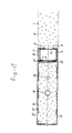
- the drawings show a channel 2 filled with bentonite 1 having a floor 3 and a front wall 4.
- a former 5 which is shown on a larger scale in Figure 2.
- This former consists of a metal tube 6 of rectangular cross-section with tubular reinforcing ribs 7 at the comers and clamps 8 and 9 respectively on the front and back wall for attaching a rubber seal 10 which is closed at the extremities and which can be inflated, as shown at 11, and then rests against the side wall 12 of the already constructed channel.
- Figure 2 shows one seal in the inflated condition and one in the uninflated condition.
- ground mill In the direction in which the channel has to be constructed a ground mill is engaged in front of the former in digging out a further section of the channel.
- This ground mill has a frame 13 to which ground mills 14 are attached in a manner known per se and which can be rotated around horizontal axes and are provided with cutting knives 15. These ground mills are driven by hydraulic motors which are not shown.
- the frame of the ground mill is attached to a rising tube 16 of rectangular cross-section, which frame is suspended at 17 on a lifting device not shown.
- the suction nozzle 18 of a suction pipe which is connected by means of a dredger pump 19 to the pressurised pipe 20.
- Water can be supplied at 23 to the tube 16 via the pipe 21 with stopcock 22.
- the fluid from this water content is indicated at 24.
- the frame 13 is provided with passage channels 25 through which the water in the tube can reach the ground mills, can mix with the loosened soil, after which the mixture of soil and water can be removed via the suction opening 18 and double-action pump 19 through the pressurised pipe 20.
- the frame 13 carries a circumferential inflatable sealing ring 26' which is constructed in a manner such that it can slide along the walls of the channel already made and along the front face 9 of the former 5.
- Figure 1 shows that the tube 16 projects above the ground level 30 and that the fluid column in the tube is higher than the bentonite column which is situated between the outside wall of the tube and the walls of the channel in the space 27.
- a pressure sensor which measures the pressure of the bentonite column.
- a pressure sensor which measures the pressure of the water column. Both measurements can be used in a manner known per se for controlling the stopcock 22 in the water supply pipe 21. As a result of this it is possible to ensure that the water column always has sufficient overpressure.
- This second former can be used as a protection for the region situated upstream, for example if it is already desired to provide a concrete filling there or if it is desired to remove the bentonite and replace it by soil after a provision has been made therein, viz. the provision for which the channel was made. This might be a watertight shield.
- the ground mill After the ground mill has constructed a new section, the ground mill has to be brought up again.
- the former 5' has now been drawn up at the correct time, then it can immediately be placed in the channel filled with bentonite immediately after the removal of the tube with mill.
Landscapes
- Engineering & Computer Science (AREA)
- Mining & Mineral Resources (AREA)
- Life Sciences & Earth Sciences (AREA)
- Civil Engineering (AREA)
- General Engineering & Computer Science (AREA)
- Structural Engineering (AREA)
- Environmental & Geological Engineering (AREA)
- Hydrology & Water Resources (AREA)
- General Life Sciences & Earth Sciences (AREA)
- Paleontology (AREA)
- Mechanical Engineering (AREA)
- Bulkheads Adapted To Foundation Construction (AREA)
Applications Claiming Priority (2)
| Application Number | Priority Date | Filing Date | Title |
|---|---|---|---|
| NL8403641 | 1984-11-29 | ||
| NL8403641A NL8403641A (nl) | 1984-11-29 | 1984-11-29 | Inrichting voor het vervaardigen van een verticale sleuf in de grond. |
Publications (2)
| Publication Number | Publication Date |
|---|---|
| EP0186921A1 true EP0186921A1 (de) | 1986-07-09 |
| EP0186921B1 EP0186921B1 (de) | 1988-09-07 |
Family
ID=19844835
Family Applications (1)
| Application Number | Title | Priority Date | Filing Date |
|---|---|---|---|
| EP19850201964 Expired EP0186921B1 (de) | 1984-11-29 | 1985-11-25 | Vorrichtung zum Herstellen eines vertikalen Kanals im Boden |
Country Status (3)
| Country | Link |
|---|---|
| EP (1) | EP0186921B1 (de) |
| DE (1) | DE3564837D1 (de) |
| NL (1) | NL8403641A (de) |
Cited By (4)
| Publication number | Priority date | Publication date | Assignee | Title |
|---|---|---|---|---|
| WO1993022241A1 (en) * | 1992-04-23 | 1993-11-11 | University Of Waterloo | System for treating polluted groundwater |
| US5800096A (en) * | 1995-04-27 | 1998-09-01 | Barrow; Jeffrey | Subsurface barrier wall and method of installation |
| US5911546A (en) * | 1989-03-03 | 1999-06-15 | University Of Waterloo | In-ground barrier |
| CN110042855A (zh) * | 2019-04-25 | 2019-07-23 | 倡创(上海)咨询管理事务所 | 混凝土防渗墙及施工方法 |
Citations (5)
| Publication number | Priority date | Publication date | Assignee | Title |
|---|---|---|---|---|
| FR1532666A (fr) * | 1967-06-13 | 1968-07-12 | Masch Und Bohrgerate Fabrik A | Procédé et dispositif de forage de trous |
| DE1634262B1 (de) * | 1966-04-09 | 1970-09-24 | Bade & Co Gmbh | Fraeswerkzeug zum Herstellen von Schlitzen fuer Schlitzwaende |
| US3564855A (en) * | 1968-04-08 | 1971-02-23 | Johann Morner | Method and device for making slit walls |
| FR2429047A1 (fr) * | 1978-06-23 | 1980-01-18 | Solmarine | Appareil permettant l'injection de produits fluides dans un volume a traiter |
| US4379658A (en) * | 1980-12-03 | 1983-04-12 | Thatcher Engineering Corporation | Method and apparatus for constructing slurry walls |
-
1984
- 1984-11-29 NL NL8403641A patent/NL8403641A/nl not_active Application Discontinuation
-
1985
- 1985-11-25 DE DE8585201964T patent/DE3564837D1/de not_active Expired
- 1985-11-25 EP EP19850201964 patent/EP0186921B1/de not_active Expired
Patent Citations (5)
| Publication number | Priority date | Publication date | Assignee | Title |
|---|---|---|---|---|
| DE1634262B1 (de) * | 1966-04-09 | 1970-09-24 | Bade & Co Gmbh | Fraeswerkzeug zum Herstellen von Schlitzen fuer Schlitzwaende |
| FR1532666A (fr) * | 1967-06-13 | 1968-07-12 | Masch Und Bohrgerate Fabrik A | Procédé et dispositif de forage de trous |
| US3564855A (en) * | 1968-04-08 | 1971-02-23 | Johann Morner | Method and device for making slit walls |
| FR2429047A1 (fr) * | 1978-06-23 | 1980-01-18 | Solmarine | Appareil permettant l'injection de produits fluides dans un volume a traiter |
| US4379658A (en) * | 1980-12-03 | 1983-04-12 | Thatcher Engineering Corporation | Method and apparatus for constructing slurry walls |
Cited By (6)
| Publication number | Priority date | Publication date | Assignee | Title |
|---|---|---|---|---|
| US5911546A (en) * | 1989-03-03 | 1999-06-15 | University Of Waterloo | In-ground barrier |
| US5957625A (en) * | 1989-03-03 | 1999-09-28 | University Of Waterloo | In-ground barrier |
| WO1993022241A1 (en) * | 1992-04-23 | 1993-11-11 | University Of Waterloo | System for treating polluted groundwater |
| US5487622A (en) * | 1992-04-23 | 1996-01-30 | University Of Waterloo | System for treating polluted groundwater |
| US5800096A (en) * | 1995-04-27 | 1998-09-01 | Barrow; Jeffrey | Subsurface barrier wall and method of installation |
| CN110042855A (zh) * | 2019-04-25 | 2019-07-23 | 倡创(上海)咨询管理事务所 | 混凝土防渗墙及施工方法 |
Also Published As
| Publication number | Publication date |
|---|---|
| DE3564837D1 (en) | 1988-10-13 |
| NL8403641A (nl) | 1986-06-16 |
| EP0186921B1 (de) | 1988-09-07 |
Similar Documents
| Publication | Publication Date | Title |
|---|---|---|
| US4904119A (en) | Process for placing a piling in the ground, a drilling machine and an arrangement for implementing this process | |
| US3965687A (en) | Apparatus for anchoring a structure to the floor of a body of water | |
| RU2712866C2 (ru) | Бурильная система с установкой для расширения ствола | |
| CN109339813A (zh) | 一种顶管掘进机 | |
| EP2586962B1 (de) | Schlammaushub-Abführsystem für eine Maschine zur Herstellung von Schlitzwänden. | |
| EP0056814A1 (de) | Schlamm-teich-verfahren sowie vorrichtung zum aufrichten unterirdischer wände | |
| US4003211A (en) | Methods and apparatus for constructing tunnels | |
| US3439953A (en) | Apparatus for and method of mining a subterranean ore deposit | |
| EP0186921B1 (de) | Vorrichtung zum Herstellen eines vertikalen Kanals im Boden | |
| USRE28945E (en) | Method and apparatus for excavating settled body of solids | |
| US3260054A (en) | Process for producing excavations in water-bearing ground | |
| GB2231601A (en) | Extracting and conveying a layer of material which is underwater | |
| US5443305A (en) | Tunnelling machine | |
| EP0580264A1 (de) | Verfahren und Grabvorrichtung zur Herstellung von Schlitzwänden | |
| CN105317065B (zh) | 同步开槽铺塑一体机 | |
| JPH07173991A (ja) | 横坑掘削装置の圧力調整装置及び横坑掘削装置の圧力調整方法 | |
| JP2840908B2 (ja) | 水底軟弱地盤改良装置及び改良方法 | |
| SU1395749A1 (ru) | Способ строительства горизонтального дренажа | |
| JPH0525988A (ja) | 立型シールド工法用のシールド機 | |
| JPH05280051A (ja) | 場所打ち式基礎工事等における固化材充填方法 | |
| JPS6131244B2 (de) | ||
| US12435630B2 (en) | Method and apparatus for use in stope backfill mining | |
| WO1988003975A1 (en) | Silos and methods of burying same | |
| GB2102043A (en) | Process and apparatus for jacking conduits in ground containing ground water | |
| US6385868B2 (en) | Jet excavating device |
Legal Events
| Date | Code | Title | Description |
|---|---|---|---|
| PUAI | Public reference made under article 153(3) epc to a published international application that has entered the european phase |
Free format text: ORIGINAL CODE: 0009012 |
|
| AK | Designated contracting states |
Kind code of ref document: A1 Designated state(s): BE DE GB NL |
|
| 17P | Request for examination filed |
Effective date: 19860620 |
|
| 17Q | First examination report despatched |
Effective date: 19880128 |
|
| GRAA | (expected) grant |
Free format text: ORIGINAL CODE: 0009210 |
|
| AK | Designated contracting states |
Kind code of ref document: B1 Designated state(s): BE DE GB NL |
|
| REF | Corresponds to: |
Ref document number: 3564837 Country of ref document: DE Date of ref document: 19881013 |
|
| PLBE | No opposition filed within time limit |
Free format text: ORIGINAL CODE: 0009261 |
|
| STAA | Information on the status of an ep patent application or granted ep patent |
Free format text: STATUS: NO OPPOSITION FILED WITHIN TIME LIMIT |
|
| 26N | No opposition filed | ||
| PGFP | Annual fee paid to national office [announced via postgrant information from national office to epo] |
Ref country code: GB Payment date: 19921116 Year of fee payment: 8 |
|
| PGFP | Annual fee paid to national office [announced via postgrant information from national office to epo] |
Ref country code: DE Payment date: 19921212 Year of fee payment: 8 |
|
| PGFP | Annual fee paid to national office [announced via postgrant information from national office to epo] |
Ref country code: BE Payment date: 19921223 Year of fee payment: 8 |
|
| PG25 | Lapsed in a contracting state [announced via postgrant information from national office to epo] |
Ref country code: GB Effective date: 19931125 |
|
| PG25 | Lapsed in a contracting state [announced via postgrant information from national office to epo] |
Ref country code: BE Effective date: 19931130 |
|
| BERE | Be: lapsed |
Owner name: HOLLANDSCHE BETON GROEP N.V. Effective date: 19931130 |
|
| GBPC | Gb: european patent ceased through non-payment of renewal fee |
Effective date: 19931125 |
|
| PG25 | Lapsed in a contracting state [announced via postgrant information from national office to epo] |
Ref country code: DE Effective date: 19940802 |
|
| PGFP | Annual fee paid to national office [announced via postgrant information from national office to epo] |
Ref country code: NL Payment date: 19991130 Year of fee payment: 15 |
|
| PG25 | Lapsed in a contracting state [announced via postgrant information from national office to epo] |
Ref country code: NL Free format text: LAPSE BECAUSE OF NON-PAYMENT OF DUE FEES Effective date: 20010601 |
|
| NLV4 | Nl: lapsed or anulled due to non-payment of the annual fee |
Effective date: 20010601 |