EP0186987B1 - Digitales Signalverarbeitungsgerät - Google Patents
Digitales Signalverarbeitungsgerät Download PDFInfo
- Publication number
- EP0186987B1 EP0186987B1 EP85308943A EP85308943A EP0186987B1 EP 0186987 B1 EP0186987 B1 EP 0186987B1 EP 85308943 A EP85308943 A EP 85308943A EP 85308943 A EP85308943 A EP 85308943A EP 0186987 B1 EP0186987 B1 EP 0186987B1
- Authority
- EP
- European Patent Office
- Prior art keywords
- processor
- channel
- channels
- sample time
- sample
- Prior art date
- Legal status (The legal status is an assumption and is not a legal conclusion. Google has not performed a legal analysis and makes no representation as to the accuracy of the status listed.)
- Expired - Lifetime
Links
Images

Classifications
-
- G—PHYSICS
- G06—COMPUTING OR CALCULATING; COUNTING
- G06F—ELECTRIC DIGITAL DATA PROCESSING
- G06F17/00—Digital computing or data processing equipment or methods, specially adapted for specific functions
- G06F17/10—Complex mathematical operations
- G06F17/15—Correlation function computation including computation of convolution operations
Definitions
- This invention concerns a digital signal processor in which a mathematical operation is carried out between non-delayed and delayed data.
- Such a processor may perform an auto or cross correlation function, or a structure function calculation.
- a typical digital correlator an input signal is divided into successive sample intervals. Digital numbers representative of the signal during each sample interval are clocked serially through the correlator for correlation. A series of digital numbers is clocked along an M-stage shift register to form a delayed signal. A non-delayed series of digital numbers is applied to one input of M different multipliers. The other input of these multipliers is taken from successive stages of the shift register. Each multiplier thus operates on a different delay. The output of each multiplier is accumulated in one of M different counters providing M different channels. At the end of an experimental run the collective content of the counters represents the correlation function of the input signal or signals.
- This correlator may be termed a linear correlator because the delay between successive channels increases linearly.
- An alternative type of digital signal processor measures the "structure function" of the input signal which for long experiments has an equivalent form to the correlation function.
- a "structurator” is required which operates exactly as a correlator described above except that the multiply circuits are replaced by circuits which subtract their two inputs and then square the results.
- the correlator may perform an auto correlation or a cross correlation on data.
- an auto correlation the input signal is replicated into two identical signals; one signal is delayed and multiplied by the other non-delayed signal.
- a cross correlator a first signal is delayed and multiplied with a second, but non delayed, signal.
- Digital signal processing enables highly accurate mathematical operations to be carried out on signals. Due to recent advances in logic speed complicated processing can be carried out in real time. Also advances in the statistical theories of some events have simplified the processing of some functions. One example of this is in laser light scattering experiments, particularly in weak scattering events.
- G.B. 2,115,192 A One solution to the problem of collecting information from many sample intervals is described in G.B. 2,115,192 A.
- the time delay between each channel is geometrically increased.
- information can be obtained from the equivalent of a delay interval of 8192 in a linear correlator e.g. G.B. 1,290,336.
- the correlator of G.B. 2,115,192 A relies on correlating a signal, at geometrically increasing delays, to obtain the maximum information for a given number of channels.
- information is still available from the non-correlated delays.
- Such uncollected information becomes more important at low counting rates.
- G.B. 2,115,192 A also applies the principle of increasing delays to a measurement of the structure function.
- the present invention extends the data collected from a correlator or structurator such as taught by G.B. 2,115,192 A, without the huge increases in equipment channels that would be involved if the linear correlator of G.B. 1,290,336 were merely extended.
- both the time delay between channels and sampling times in successive channels are progressively increased.
- a multi-channel digital signal processor comprises:- means for receiving series of digital numbers in successive sample time intervals (T); an accumulator for counting the total number of digital signals received; a plurality of channels having a series of delays along which a series of digital numbers is transferred to provide a delayed signal, an arithmetic section for receiving at one input a digital signal and at another input the delayed signal, and an accumulator for receiving the output of the arithmetic section; and means for increasing the delay ( ⁇ ) in successive channels characterised by a separate series of delays associated with each channel means for progressively increasing the sample time interval (T s ) in successive channels.
- the arithmetic section may be a multiplier, in which case the processor is a correlator.
- the arithmetic section may be a difference squarer circuit, in which case the processor is a structurator.
- the delayed signal in each channel may be obtained by clocking a digital signal along a multistage multibit shift register.
- the means for progressively increasing the channel sample time (T s ) may be frequency dividers set to divide the sample time T by set amounts to clock the delayed signal. These frequency dividers may have fixed values or be changeable to suit differing experiments.
- the increase in T s between channels m and m-1 may be a constant multiplicative factor i.e. so that ⁇ may be an integer or may take a non-integral value with ⁇ m-1 rounded to the nearest integer.
- the delay time ⁇ may be a fixed or variable multiple of T s e.g. where ⁇ is an integer.
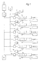
- Figure 1 is a schematic view of the correlator
- Figure 2 is a graph showing the signal to be correlated.
- the dilation factor ⁇ (equation 1) is 2 and the delay factor ⁇ is 3.
- the correlation circuitry of Figure 1 receives a signal from a photomultiplier, indicated by numeral 1.
- the photo-multiplier output is a stream of pulses each representing receipt of a photon in a light flux 2. These pulses have a random distribution of amplitude and charge. They are converted to pulses of equal amplitude and duration by the standardisation circuitry 3.
- the correlator has M channels, typical M is 24. The number used depends on the nature of the experiment being investigated, frequently only the first 10 or so channels will be needed.
- Each channel comprises a counter 5, a shift register 6, a multi-bit multiplier 7, and an accumulator 8.
- the shift registers 6 1-M are multibit and of any desired number of stages.
- the multipliers 7 1-M connect to stages 1 and 4 of the register 6 1-M and feed into the accumulators 8 1-M to form a (stationary) time average as explained later.
- the multipliers (7 m ) are connected to stage 1 and n (n > 3) of the register to suit experimental conditions.
- the counters 5 1-M receive pulses from the standardiser 3. Sample time clock pulses of duration T are sent to each shift register via frequency dividers 9 set for this example, as listed in Table 1.
- T s (m) is the sample time used in channel m. It is the fundamental clock sample time T multiplied by the number set by the divider circuit 9 m .
- the delay tine ⁇ (m) is the delay in time between the non-delayed and delayed inputs to the multiplier 7 m .
- Accumulator 10 accumulates standardised pulses for the duration of an experiment to form as explained later.
- Accumulator 11 collects clock pulses of duration T over an experiment to provide N, the total number of clock pulses.
- T ut
- n can be set between 1 and 3200 and t can be one microsec.
- T in this example can be varied between 1 microsec and 32 millisec.
- the contents of all the correlator stores, counters 5, accumulators 8, 10, and 11 and registers 6, are set to zero.
- Light from an experiment, e.g. scattered by a particle suspension, is received by the photomultiplier 1 whose output is fed to the standardiser 3. Pulses from the standardiser 3 enter the counters 5 and are clocked at the appropriate channel sample times.
- N (m) is the total number of sample times appropriate to channel m which have occurred in the duration of the experiment. It is related to the total number N of sample times T, obtained from accumulator 11, through the relation where f (m) is the divide frequency set in divider 9 m . Also at the end of the experiment, accumulator 10 contains the value corresponding to the total number of pulses n p accumulated during the experiment. The average number of pulses obtained in one sample time T s (m) , appropriate to channel m, is thus
- the correlation function g (2) [ ⁇ (m) ] of the input signals defined by where is the number of pulses counted in sample time T s (m) centred at time t d and the ⁇ ....> represent a long-time average.
- ⁇ is the decay rate of the correlation function
- D T is the translational diffusion coefficient of the particles ⁇ , the light wavelength, ⁇ , the scattering angle.
- the quantity g (2) [ ⁇ (m) ] is obtained from the accumulator outputs from the following calculation:
- the structurator gives an estimate of the same function by the relation
- the correlator described above could be adapted in several ways:-
- the divide frequencies set in dividers 9 and the shift register stages connected by multipliers 7 could be programmed to any values to suit experimental needs.
- the correlator may be adapted via switches (not shown) to connect as a linear correlator on all channels. This could incorporate extending the shift register in the first channel to have the same number of stages as the number of channels.
- the multipliers 7 1 to M would then connect via the switches to the first stage and to successive stages of this extended shift register 6 1 .
- the correlator operations described above could be performed in software by a suitably interfaced computer (rather than using the hardware described above).
- the input of multipliers 7 connected to stage 1 of the shift register 6 in Figure 1 could instead be fed by additional counters, similar to 5, fed in turn by a standardiser, similar to 3, operating on the second signal.
- the growing correlation function could be displayed on an oscilloscope after each sample interval T s (m) in the unnormalised form
Landscapes
- Engineering & Computer Science (AREA)
- Physics & Mathematics (AREA)
- General Physics & Mathematics (AREA)
- Mathematical Physics (AREA)
- Computational Mathematics (AREA)
- Theoretical Computer Science (AREA)
- Mathematical Analysis (AREA)
- Mathematical Optimization (AREA)
- Pure & Applied Mathematics (AREA)
- Data Mining & Analysis (AREA)
- Algebra (AREA)
- Databases & Information Systems (AREA)
- Software Systems (AREA)
- General Engineering & Computer Science (AREA)
- Computing Systems (AREA)
- Investigating Or Analysing Materials By Optical Means (AREA)
- Complex Calculations (AREA)
Claims (9)
- Digitaler Signalprozessor mit
Mitteln (1) zum Empfangen einer Abfolge (2) von digitalen Ziffern in aufeinanderfolgenden Abtastzeitintervallen (T);
einem Akkumulator (10) zum Zählen der Gesamtzahl von empfangenen Signalen;
mehreren Kanälen (Kanal 1... Kanal M) mit einer Abfolge von Verzögerungen (6), längs derer eine Abfolge von digitalen Ziffern übertragen wird, um ein verzögertes Signal bereitzustellen,
einem Arithmetikabschnitt (7), der an einem Eingang ein digitales Signal und an einem anderen Eingang das verzögerte Signal empfängt,
einem Akkumulator (8) zum Empfangen der Ausgabe des Arithmetikabschnitts (7); und
Mitteln (5) zur Vergrößerung der Verzögerung (τ) in aufeinanderfolgenden Kanälen,
gekennzeichnet durch
eine getrennte Abfolge von mit jedem Kanal verbundenen Verzögerungen (6),
Mittel (9), um zunehmend das Abtastzeitintervall (Ts) in aufeinanderfolgenden Kanälen zu erhöhen. - Prozessor nach Anspruch 1, bei dem die Mittel (9) zur zunehmenden Erhöhung der Kanalabtastzeit (Ts) Frequenzteiler sind, die die Abtastzeit (T) durch vorbestimmte Werte teilen.
- Prozessor nach Anspruch 2, bei dem die Frequenzteiler (9) eingestellt werden können, um einige Kanalabtastzeiten (Ts) zu ändern.
- Prozessor nach Anspruch 1, bei dem die Verzögerungszeit (τ(m)) in allen Kanälen eine feste Beziehung zur Kanalabtastzeit (Ts (m)) hat, wobei m eine ganze Zahl gleich einer Kanalnummer ist.
- Prozessor nach Anspruch 4, bei dem die Zunahme (α) der Abtastzeit (Ts) zwischen aufeinanderfolgenden Kanälen gleich zwei ist und die Verzögerungszeit (τ) in jedem Kanal gleich der Zahl drei (β = 3) multipliziert mit der zugeordneten Kanalabtastzeit (Ts (m)) ist, wobei m eine ganze Zahl gleich einer Kanalnummer ist.
- Prozessor nach Anspruch 1, bei dem die Verzögerungszeit (τ(m)) in jedem Kanal (m) verändert werden kann.
- Prozessor nach Anspruch 1, bei dem der Arithmetikabschnitt (7) ein Multiplizierer ist.
- Prozessor nach Anspruch 1, bei dem der Arithmetikabschnitt (7) ein Differenzquadrierer ist.
- Prozessor nach Anspruch 1, der weiterhin Schalter zum Schalten der Eingänge der Arithmetikabschnitte (7) aufweist, wobei der Prozessor als Linearprozessor konstruiert ist.
Applications Claiming Priority (2)
| Application Number | Priority Date | Filing Date | Title |
|---|---|---|---|
| GB848431837A GB8431837D0 (en) | 1984-12-17 | 1984-12-17 | Digital signal processor |
| GB8431837 | 1984-12-17 |
Publications (3)
| Publication Number | Publication Date |
|---|---|
| EP0186987A2 EP0186987A2 (de) | 1986-07-09 |
| EP0186987A3 EP0186987A3 (en) | 1988-02-24 |
| EP0186987B1 true EP0186987B1 (de) | 1991-06-05 |
Family
ID=10571321
Family Applications (1)
| Application Number | Title | Priority Date | Filing Date |
|---|---|---|---|
| EP85308943A Expired - Lifetime EP0186987B1 (de) | 1984-12-17 | 1985-12-09 | Digitales Signalverarbeitungsgerät |
Country Status (5)
| Country | Link |
|---|---|
| US (1) | US4809210A (de) |
| EP (1) | EP0186987B1 (de) |
| JP (1) | JPH0636165B2 (de) |
| DE (1) | DE3583128D1 (de) |
| GB (1) | GB8431837D0 (de) |
Families Citing this family (3)
| Publication number | Priority date | Publication date | Assignee | Title |
|---|---|---|---|---|
| GB8628397D0 (en) * | 1986-11-27 | 1986-12-31 | Secr Defence | Digital correlator/structurator |
| GB2381607A (en) * | 2001-11-01 | 2003-05-07 | Matthew James Johnson | Serila-parallel correlator architecture |
| JP5057922B2 (ja) * | 2006-12-28 | 2012-10-24 | 株式会社堀場製作所 | コリレータ |
Citations (1)
| Publication number | Priority date | Publication date | Assignee | Title |
|---|---|---|---|---|
| GB2115192A (en) * | 1982-02-15 | 1983-09-01 | Secr Defence | Correlation |
Family Cites Families (3)
| Publication number | Priority date | Publication date | Assignee | Title |
|---|---|---|---|---|
| US3842252A (en) * | 1969-03-26 | 1974-10-15 | Nat Res Dev | Optical signal processing |
| GB1477833A (en) * | 1973-08-24 | 1977-06-29 | Nat Res Dev | Apparatus for comparing two binary signals |
| US4071903A (en) * | 1976-08-04 | 1978-01-31 | International Business Machines Corporation | Autocorrelation function factor generating method and circuitry therefor |
-
1984
- 1984-12-17 GB GB848431837A patent/GB8431837D0/en active Pending
-
1985
- 1985-12-09 EP EP85308943A patent/EP0186987B1/de not_active Expired - Lifetime
- 1985-12-09 DE DE8585308943T patent/DE3583128D1/de not_active Expired - Lifetime
- 1985-12-17 JP JP60282134A patent/JPH0636165B2/ja not_active Expired - Lifetime
- 1985-12-17 US US06/809,782 patent/US4809210A/en not_active Expired - Lifetime
Patent Citations (1)
| Publication number | Priority date | Publication date | Assignee | Title |
|---|---|---|---|---|
| GB2115192A (en) * | 1982-02-15 | 1983-09-01 | Secr Defence | Correlation |
Also Published As
| Publication number | Publication date |
|---|---|
| DE3583128D1 (de) | 1991-07-11 |
| GB8431837D0 (en) | 1985-01-30 |
| EP0186987A2 (de) | 1986-07-09 |
| JPH0636165B2 (ja) | 1994-05-11 |
| EP0186987A3 (en) | 1988-02-24 |
| US4809210A (en) | 1989-02-28 |
| JPS61198368A (ja) | 1986-09-02 |
Similar Documents
| Publication | Publication Date | Title |
|---|---|---|
| EP0086570B1 (de) | Digitales Signalverarbeitungsgerät | |
| US8290751B2 (en) | Multi-gain adaptive linear processing and gated digital system for use in flow cytometry | |
| Warburton et al. | Digital pulse processing: new possibilities in nuclear spectroscopy | |
| US6208285B1 (en) | Pulse compressor for doppler tolerant radar | |
| US7564386B2 (en) | Pre-processing data samples from parallelized data converters | |
| Ables et al. | A 1024− channel digital correlator | |
| EP0333732B1 (de) | Digitaler korrelator | |
| HU210832B (en) | Method for processing signals and adaptive implementation of said method for nuclear spectrometers | |
| EP0186987A2 (de) | Digitales Signalverarbeitungsgerät | |
| US4223270A (en) | Multiplexed CCD pulse width discriminator | |
| RU2012056C1 (ru) | Устройство для распознавания ситуаций | |
| Cooper | 3.5. Autocorrelation Spectrometers | |
| Dominguez-Tenreiro et al. | Field effects on the luminosity segregation analysis of distant clusters of galaxies | |
| US4605913A (en) | Transversal filter having an analog shift register | |
| Phillies | On the temporal resolution of multitau digital correlators | |
| SU703826A1 (ru) | Многоканальный цифровой фильтр | |
| Thomas et al. | Microprocessor‐based digital correlator | |
| KR950024195A (ko) | 합성서브밴드 필터 | |
| Bordessoule et al. | Highly integrated pulse processor | |
| Oliver | Recent Developments in Photon Correlation and Spectrum Analysis Techniques: I. Instrumentation for Photodetection Spectroscopy | |
| RU2018144C1 (ru) | Цифровой анализатор спектра | |
| Koper et al. | The look‐up table: A logarithmic converter for cell sorters | |
| Albertson et al. | A Study of Pileup and Electronic Noise in the ATLAS Liquid Argon Presampler Detector | |
| DiVito | The development of a data acquisition system for a vacuum-ultraviolet spectroradiometer | |
| Mayo Jr | Digital Photon Correlation Data Processing Techniques |
Legal Events
| Date | Code | Title | Description |
|---|---|---|---|
| PUAI | Public reference made under article 153(3) epc to a published international application that has entered the european phase |
Free format text: ORIGINAL CODE: 0009012 |
|
| AK | Designated contracting states |
Kind code of ref document: A2 Designated state(s): DE FR GB IT |
|
| PUAL | Search report despatched |
Free format text: ORIGINAL CODE: 0009013 |
|
| AK | Designated contracting states |
Kind code of ref document: A3 Designated state(s): DE FR GB IT |
|
| 17P | Request for examination filed |
Effective date: 19880514 |
|
| 17Q | First examination report despatched |
Effective date: 19890621 |
|
| ITF | It: translation for a ep patent filed | ||
| GRAA | (expected) grant |
Free format text: ORIGINAL CODE: 0009210 |
|
| AK | Designated contracting states |
Kind code of ref document: B1 Designated state(s): DE FR GB IT |
|
| ET | Fr: translation filed | ||
| REF | Corresponds to: |
Ref document number: 3583128 Country of ref document: DE Date of ref document: 19910711 |
|
| PLBE | No opposition filed within time limit |
Free format text: ORIGINAL CODE: 0009261 |
|
| STAA | Information on the status of an ep patent application or granted ep patent |
Free format text: STATUS: NO OPPOSITION FILED WITHIN TIME LIMIT |
|
| 26N | No opposition filed | ||
| REG | Reference to a national code |
Ref country code: GB Ref legal event code: 732E |
|
| REG | Reference to a national code |
Ref country code: GB Ref legal event code: IF02 |
|
| REG | Reference to a national code |
Ref country code: FR Ref legal event code: TP |
|
| PGFP | Annual fee paid to national office [announced via postgrant information from national office to epo] |
Ref country code: FR Payment date: 20041111 Year of fee payment: 20 |
|
| PGFP | Annual fee paid to national office [announced via postgrant information from national office to epo] |
Ref country code: GB Payment date: 20041116 Year of fee payment: 20 |
|
| PGFP | Annual fee paid to national office [announced via postgrant information from national office to epo] |
Ref country code: DE Payment date: 20041117 Year of fee payment: 20 |
|
| PG25 | Lapsed in a contracting state [announced via postgrant information from national office to epo] |
Ref country code: GB Free format text: LAPSE BECAUSE OF EXPIRATION OF PROTECTION Effective date: 20051208 |
|
| REG | Reference to a national code |
Ref country code: GB Ref legal event code: PE20 |