EP0186997A2 - Anzeigevorrichtungen, Fachunterteilungen und dergleichen - Google Patents
Anzeigevorrichtungen, Fachunterteilungen und dergleichen Download PDFInfo
- Publication number
- EP0186997A2 EP0186997A2 EP85309033A EP85309033A EP0186997A2 EP 0186997 A2 EP0186997 A2 EP 0186997A2 EP 85309033 A EP85309033 A EP 85309033A EP 85309033 A EP85309033 A EP 85309033A EP 0186997 A2 EP0186997 A2 EP 0186997A2
- Authority
- EP
- European Patent Office
- Prior art keywords
- display system
- panel
- pole
- frame
- section
- Prior art date
- Legal status (The legal status is an assumption and is not a legal conclusion. Google has not performed a legal analysis and makes no representation as to the accuracy of the status listed.)
- Withdrawn
Links
- 238000005192 partition Methods 0.000 title description 4
- 230000000712 assembly Effects 0.000 claims abstract description 12
- 238000000429 assembly Methods 0.000 claims abstract description 12
- XAGFODPZIPBFFR-UHFFFAOYSA-N aluminium Chemical compound [Al] XAGFODPZIPBFFR-UHFFFAOYSA-N 0.000 description 1
- 229910052782 aluminium Inorganic materials 0.000 description 1
- 239000004411 aluminium Substances 0.000 description 1
- 238000010276 construction Methods 0.000 description 1
- 238000001125 extrusion Methods 0.000 description 1
- 238000010079 rubber tapping Methods 0.000 description 1
- 238000000638 solvent extraction Methods 0.000 description 1
Images


Classifications
-
- A—HUMAN NECESSITIES
- A47—FURNITURE; DOMESTIC ARTICLES OR APPLIANCES; COFFEE MILLS; SPICE MILLS; SUCTION CLEANERS IN GENERAL
- A47F—SPECIAL FURNITURE, FITTINGS, OR ACCESSORIES FOR SHOPS, STOREHOUSES, BARS, RESTAURANTS OR THE LIKE; PAYING COUNTERS
- A47F11/00—Arrangements in shop windows, shop floors or show cases
- A47F11/02—Removable walls, scaffolding or the like; Pillars; Special curtains or the like
-
- E—FIXED CONSTRUCTIONS
- E04—BUILDING
- E04B—GENERAL BUILDING CONSTRUCTIONS; WALLS, e.g. PARTITIONS; ROOFS; FLOORS; CEILINGS; INSULATION OR OTHER PROTECTION OF BUILDINGS
- E04B2/00—Walls, e.g. partitions, for buildings; Wall construction with regard to insulation; Connections specially adapted to walls
- E04B2/74—Removable non-load-bearing partitions; Partitions with a free upper edge
- E04B2/7407—Removable non-load-bearing partitions; Partitions with a free upper edge assembled using frames with infill panels or coverings only; made-up of panels and a support structure incorporating posts
- E04B2/7416—Removable non-load-bearing partitions; Partitions with a free upper edge assembled using frames with infill panels or coverings only; made-up of panels and a support structure incorporating posts with free upper edge, e.g. for use as office space dividers
- E04B2/7433—Removable non-load-bearing partitions; Partitions with a free upper edge assembled using frames with infill panels or coverings only; made-up of panels and a support structure incorporating posts with free upper edge, e.g. for use as office space dividers with panels and support posts
- E04B2/7438—Removable non-load-bearing partitions; Partitions with a free upper edge assembled using frames with infill panels or coverings only; made-up of panels and a support structure incorporating posts with free upper edge, e.g. for use as office space dividers with panels and support posts with adjustable angular connection of panels to posts
- E04B2/744—Removable non-load-bearing partitions; Partitions with a free upper edge assembled using frames with infill panels or coverings only; made-up of panels and a support structure incorporating posts with free upper edge, e.g. for use as office space dividers with panels and support posts with adjustable angular connection of panels to posts using angularly-spaced longitudinal grooves of the posts
-
- G—PHYSICS
- G09—EDUCATION; CRYPTOGRAPHY; DISPLAY; ADVERTISING; SEALS
- G09F—DISPLAYING; ADVERTISING; SIGNS; LABELS OR NAME-PLATES; SEALS
- G09F15/00—Boards, hoardings, pillars, or like structures for notices, placards, posters, or the like
- G09F15/0068—Modular articulated structures, e.g. stands, and articulation means therefor
Definitions
- THIS INVENTION relates to display systems, partitions and other such structures, particularly of the kind adapted to be easily transportable.
- the panel and pole system allows assembly of the display or partition structure by providing a plurality of panels, each of which is releasably securable to rigid upright poles interposed therebetween and in this manner structures of varying sizes and shapes can be quickly constructed from a single portable kit.
- a major advantage of this system is - that the resulting structure is extremely strong and rigid.
- disadvantages are that assembly can be time consuming and because the components of the structure are separate, such components can become mislaid or lost.
- the folding display system typically comprises a single assembly of panels each interconnected by hinges which allow where necessary 360° movement of the panels such that the structure can be closed to a position where it occupies a relatively small space.
- the major advantage of this system over the panel and pole system is that assembly of the required structure is very simple and quick.
- disadvantages of this sytem are that it is inherently less rigid than that of the panel and pole system and the number and variety of configurations which can be adopted is limited by the fact that the panels have to be interconnected by hinges.
- a portable display system comprising a plurality of panel assemblies adapted to be selectively connectable to each other by hinging means to form a rigid foldable display structure, or alternatively to a plurality of poles to form a rigid non-foldable display structure.
- the invention thus provides a single display system which can be used either as a folding structure analogous to the conventional folding display system described or a different configuration can be utilised analogous to the panel and pole system, whichever is desired.
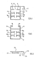
- a section of an elongate aluminium member comprising a generally box-like structure 1 from one side of which extends a lip 2 defining a channel 3.
- a lip 2 defining a channel 3.
- Within the box 1 are two pairs of oppositely disposed ribs 4, 5, 6 and 7, on the end of each of which is an arcuate portion 4a, 5a, 6a, and 7a arranged such that opposing pairs of ribs 4 and 7 or 5 and 6 each define a part cylindrical channel.
- a pair of oppositely disposed planar ribs 8, 9 defining a gap 10.
- FIG. 2 of the drawings there is shown another section of an elongate member comprising a box 11 within which are two pairs of oppositely disposed arcuate ribs 12, 13, 14 and 15 also having identical arcuate portions 12a, 13a, 14a and 15a to those corresponding portions shown in Fig. 1.
- Extending outwardly from one side of the box 11 are a pair of walls 16, 17 on the free end of each of which is a respective inwardly facing lip portion 18, 19.
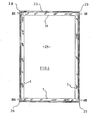
- FIGs. 4 and 5 there is shown schematically the arrangement by which the members of Figs. 1 to 3 can be assembled to form a panel assembly 25.
- Three elongate sections of member 1 are arranged at right-angles to each other to form two sides and a base. Suitable portions thereof are cut out to provide butt fixing at the two corners 26, 27 thereof.
- the top portion of the panel assembly 25 is comprised partly of the member 11 shown in Fig. 2 and each end thereof is suitably cut out at the corners 28, 29.
- screw holes may be drilled as appropriate and self-tapping screws as shown inserted into the part-cylindrical channels afforded by the arcuate portions of the ribs 4, 5, 6, 7, 12, 13, 14 and 15 as appropriate.
- the structure is completed by the addition of the member 20 shown in Fig. 3 which is slidably affixed to the member 11 as shown in Fig. 5.
- This arrangement permits a rectangular panel (not shown) to be releasably secured within the panel assembly 25 where it is received at its side and lower edges by the channel 3 of the member 1, and at its top edge by the channel 24 of the member 20.
- a sprung ball 30 shown in dotted outline, is fixed in the member 11 and is adapted to be engagable with a recess (not shown) on the underside of the member 20.
- Fig. 6 there is shown one manner in which adjacent panel assemblies 25 can be connected to each other by hinging means which comprises a double-action hinge 31 permitting arcuate movement of either panel assembly 25 through approximately 360°. This permits adjacent rows of panel assemblies to be closed into a concertina-like configuration for easy storage and transportation.
- hinging means which comprises a double-action hinge 31 permitting arcuate movement of either panel assembly 25 through approximately 360°. This permits adjacent rows of panel assemblies to be closed into a concertina-like configuration for easy storage and transportation.
- Figs. 7a to 7e there are shown various configurations which may be adopted by hinging adjacent panel assemblies together in the manner shown.
- Fig. 7a it will be seen that a five panelled assembly can be folded into a box structure.
- FIG. 7b an eight panel assembly hinged in the manner shown can be used to form a corner unit with a projecting portion upon which a shelf can be fixed.
- an eight panel assembly can form a three wall structure with a projecting box-like feature on which can be affixed a table top if desired.
- a seven panel unit can be used to form a generally rectangular display having a forwardly projecting corner piece.
- Fig. 7e a seven panel assembly in which two of the panels are smaller than the others can be utilised to make up a structure in the shape of a pair of adjacent boxes having different dimensions and upon which a shelf and a table top can be secured.
- the peg 35 Around the periphery of the pole are eight part cylindrical channels 34 which are each shaped to receive by push or snap fit a peg 35, shown in detail in Fig. 9.
- the peg 35 has an enlarged arcuate head 36 of shape corresponding to that of the channels 34 in the pole 32.
- Extending from the head 36 is a shaft portion 37 on the end of which is a screw portion 38 adapted to be received in the holes which would otherwise be occupied by the hinge mounting screws described with reference to the embodiment of the invention shown in Figs. 1 to 7.
- Fig. 10 there is shown an alternative form of peg 39 which differs from that shown in Fig. 9 by the fact that the enlarged head portion 40 is generally spherical and this has the advantage in that the head portion 40 does not have to be aligned vertically with a particular channel 34 on the extrusion 32, as would be the case if the peg 35 were utilised instead.
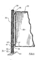
- FIG. 11 of the drawings there is shown a partly-erected structure utilising lengths of poles 32 and the pegs 35.
- Each length of pole 32 is joined to the next with the aid of a connector plate 41, from each side of which protrudes vertically a square section bar 42, 43 (shown in dotted outline) which is received in the square hole 33 of each pole 32.
- a foot portion 44 is provided on the end of each pole 32 adjacent the floor and is similarly provided with a square-section bar 45 (shown in dotted outline), which extends upwardly and is similarly received in the square hole 33 of the pole 32.
- Adjacent panels 25 can be connected to the structure by a snap or push fit of each peg 35 into an appropriate channel portion 34 and because there are eight of such channel portions 34 on each pole 32 it follows that a wide variety of configurations can be adopted.
- an agruative form of frame member comprises in section, a generally box-like structure of outer walls 50, one of which extends beyond the bounds of the box to provide a lip 51 defining a channel 52.
- ribs 53 and 54 integral with and extending inwardly from two opposed walls 50.
- the rib 54 carries a part cylindrical channel 55 which is oppositely disposed with respect to a further similar channel 56 extending inwardly from another outer wall 50.
- channels 55 and 56 are adapted to receive screws securing the frame members together.
- the embodiment of the invention described above is merely illustrative of one manner in which the invention can be achieved.
- the pole shown in Fig. 8 may, instead of being generally circular, be of a polygonal shape such as an octogon, on the flattened surfaces of which are the channels adapted to receive pegs.
- the poles instead of providing poles with external elongate slots, the poles may instead be tubular having key hole-shaped cut-out portions at spaced intervals therealong. The enlarged head portion of pegs 35 or 39 can then be inserted into the circular part of the key-hole and then moved axially to a position in which it is trapped behind the slotted portion of the key-hole.
Landscapes
- Engineering & Computer Science (AREA)
- Physics & Mathematics (AREA)
- Architecture (AREA)
- Electromagnetism (AREA)
- Civil Engineering (AREA)
- Structural Engineering (AREA)
- General Physics & Mathematics (AREA)
- Theoretical Computer Science (AREA)
- Devices For Indicating Variable Information By Combining Individual Elements (AREA)
- Display Racks (AREA)
Applications Claiming Priority (2)
| Application Number | Priority Date | Filing Date | Title |
|---|---|---|---|
| GB08431637A GB2174833A (en) | 1984-12-14 | 1984-12-14 | Display systems |
| GB8431637 | 1984-12-14 |
Publications (2)
| Publication Number | Publication Date |
|---|---|
| EP0186997A2 true EP0186997A2 (de) | 1986-07-09 |
| EP0186997A3 EP0186997A3 (de) | 1988-12-14 |
Family
ID=10571208
Family Applications (1)
| Application Number | Title | Priority Date | Filing Date |
|---|---|---|---|
| EP85309033A Withdrawn EP0186997A3 (de) | 1984-12-14 | 1985-12-12 | Anzeigevorrichtungen, Fachunterteilungen und dergleichen |
Country Status (2)
| Country | Link |
|---|---|
| EP (1) | EP0186997A3 (de) |
| GB (1) | GB2174833A (de) |
Cited By (2)
| Publication number | Priority date | Publication date | Assignee | Title |
|---|---|---|---|---|
| EP0257799A1 (de) * | 1986-07-24 | 1988-03-02 | Nimlok Limited | Schirmzusammensetzung |
| WO1999017268A1 (en) * | 1997-09-29 | 1999-04-08 | Bengt Olof Davidsson | A frame device |
Family Cites Families (14)
| Publication number | Priority date | Publication date | Assignee | Title |
|---|---|---|---|---|
| DE673146C (de) * | 1936-03-01 | 1939-03-16 | Adolf Roevenstrunk | Staender fuer Ausstellungsgegenstaende o. dgl. |
| US3571999A (en) * | 1969-07-02 | 1971-03-23 | John G Downing | Knockdown display |
| US3608221A (en) * | 1969-12-08 | 1971-09-28 | Museum Planning Inc | Display panel |
| FR2210238A5 (de) * | 1972-12-13 | 1974-07-05 | Pariente Roger | |
| US3798863A (en) * | 1973-01-08 | 1974-03-26 | American Metal Climax Inc | Frame corner construction |
| GB1492615A (en) * | 1974-02-08 | 1977-11-23 | Kepac Ltd | Screen constructions |
| GB1579620A (en) * | 1977-08-19 | 1980-11-19 | Batzner Coulthard Dokumentatio | Display screens |
| US4147198A (en) * | 1977-10-03 | 1979-04-03 | Extraversion, Inc. | Portable display system |
| USRE30777E (en) * | 1977-10-03 | 1981-10-20 | Extraversion, Inc. | Portable display system |
| DE2846104A1 (de) * | 1977-10-24 | 1979-06-07 | Sony Corp | Ausstellungsvorrichtung |
| US4436135A (en) * | 1980-01-28 | 1984-03-13 | Extraversion, Inc. | Portable display system |
| GB2074355A (en) * | 1980-04-22 | 1981-10-28 | Runacres Fowler Ltd | Display Stands |
| GB2084375A (en) * | 1980-09-27 | 1982-04-07 | Batzner Coulthard Dokumentatio | Display Systems |
| GB2130780B (en) * | 1982-10-13 | 1986-08-20 | Cannon Davis Ass Ltd | Fastening display sheets to display panels |
-
1984
- 1984-12-14 GB GB08431637A patent/GB2174833A/en not_active Withdrawn
-
1985
- 1985-12-12 EP EP85309033A patent/EP0186997A3/de not_active Withdrawn
Cited By (2)
| Publication number | Priority date | Publication date | Assignee | Title |
|---|---|---|---|---|
| EP0257799A1 (de) * | 1986-07-24 | 1988-03-02 | Nimlok Limited | Schirmzusammensetzung |
| WO1999017268A1 (en) * | 1997-09-29 | 1999-04-08 | Bengt Olof Davidsson | A frame device |
Also Published As
| Publication number | Publication date |
|---|---|
| GB2174833A (en) | 1986-11-12 |
| EP0186997A3 (de) | 1988-12-14 |
| GB8431637D0 (en) | 1985-01-30 |
Similar Documents
| Publication | Publication Date | Title |
|---|---|---|
| US5245802A (en) | Portable collapsible building system | |
| US6332657B1 (en) | Set of construction elements for furniture | |
| US5680737A (en) | Structural connector hub for exhibit booths | |
| US5522344A (en) | Collapsible, window-mounted pet cage | |
| US5170977A (en) | Corner bracket | |
| US5768845A (en) | Module panel and assembly | |
| US4712336A (en) | Interconnecting "full bleed" modular panel and connective hardware system to form a variety of exhibit and office interior enclosures | |
| US4084360A (en) | Combination spline groove | |
| CA2245624C (en) | Prefabricated plastic shed and components therefor | |
| US5313747A (en) | Collapsible and extensible playhouse | |
| US5996299A (en) | Partition wall material | |
| US4986038A (en) | Component exhibit system | |
| US3222829A (en) | Knockdown shelter | |
| US6607421B1 (en) | Folding structure | |
| WO2003087490A1 (en) | Snap panel display unit | |
| US6378712B1 (en) | Whatnot | |
| US4888895A (en) | Portable display system | |
| KR830005036A (ko) | 콘테이너형 단위구조체및 이를 축조한 조립 구조물 | |
| US4733507A (en) | Isolation hut | |
| US8967739B2 (en) | Modular exhibit structure | |
| US4877213A (en) | Conference easel | |
| WO1987003321A1 (en) | Panel structures | |
| EP0186997A2 (de) | Anzeigevorrichtungen, Fachunterteilungen und dergleichen | |
| JP3406472B2 (ja) | フェンス | |
| US3999342A (en) | Structure for exhibition purposes |
Legal Events
| Date | Code | Title | Description |
|---|---|---|---|
| PUAI | Public reference made under article 153(3) epc to a published international application that has entered the european phase |
Free format text: ORIGINAL CODE: 0009012 |
|
| AK | Designated contracting states |
Kind code of ref document: A2 Designated state(s): AT BE CH DE FR GB IT LI LU NL SE |
|
| RAP1 | Party data changed (applicant data changed or rights of an application transferred) |
Owner name: ALPHA TECHNICS LIMITED |
|
| RAP1 | Party data changed (applicant data changed or rights of an application transferred) |
Owner name: SILK CUT FLOWERS LIMITED |
|
| PUAL | Search report despatched |
Free format text: ORIGINAL CODE: 0009013 |
|
| AK | Designated contracting states |
Kind code of ref document: A3 Designated state(s): AT BE CH DE FR GB IT LI LU NL SE |
|
| STAA | Information on the status of an ep patent application or granted ep patent |
Free format text: STATUS: THE APPLICATION IS DEEMED TO BE WITHDRAWN |
|
| 18D | Application deemed to be withdrawn |
Effective date: 19890615 |
|
| RIN1 | Information on inventor provided before grant (corrected) |
Inventor name: CHURCH, BARRY ALAN Inventor name: LEECH, ANDREW JOHN |