EP0187084A1 - Verbindungsvorrichtung zwischen einem homokinetischen Gelenk und einer Ausgangswelle - Google Patents
Verbindungsvorrichtung zwischen einem homokinetischen Gelenk und einer Ausgangswelle Download PDFInfo
- Publication number
- EP0187084A1 EP0187084A1 EP85402447A EP85402447A EP0187084A1 EP 0187084 A1 EP0187084 A1 EP 0187084A1 EP 85402447 A EP85402447 A EP 85402447A EP 85402447 A EP85402447 A EP 85402447A EP 0187084 A1 EP0187084 A1 EP 0187084A1
- Authority
- EP
- European Patent Office
- Prior art keywords
- flange
- output shaft
- face
- constant velocity
- velocity joint
- Prior art date
- Legal status (The legal status is an assumption and is not a legal conclusion. Google has not performed a legal analysis and makes no representation as to the accuracy of the status listed.)
- Granted
Links
Images
Classifications
-
- F—MECHANICAL ENGINEERING; LIGHTING; HEATING; WEAPONS; BLASTING
- F16—ENGINEERING ELEMENTS AND UNITS; GENERAL MEASURES FOR PRODUCING AND MAINTAINING EFFECTIVE FUNCTIONING OF MACHINES OR INSTALLATIONS; THERMAL INSULATION IN GENERAL
- F16D—COUPLINGS FOR TRANSMITTING ROTATION; CLUTCHES; BRAKES
- F16D3/00—Yielding couplings, i.e. with means permitting movement between the connected parts during the drive
- F16D3/16—Universal joints in which flexibility is produced by means of pivots or sliding or rolling connecting parts
- F16D3/20—Universal joints in which flexibility is produced by means of pivots or sliding or rolling connecting parts one coupling part entering a sleeve of the other coupling part and connected thereto by sliding or rolling members
- F16D3/202—Universal joints in which flexibility is produced by means of pivots or sliding or rolling connecting parts one coupling part entering a sleeve of the other coupling part and connected thereto by sliding or rolling members one coupling part having radially projecting pins, e.g. tripod joints
- F16D3/205—Universal joints in which flexibility is produced by means of pivots or sliding or rolling connecting parts one coupling part entering a sleeve of the other coupling part and connected thereto by sliding or rolling members one coupling part having radially projecting pins, e.g. tripod joints the pins extending radially outwardly from the coupling part
- F16D3/2055—Universal joints in which flexibility is produced by means of pivots or sliding or rolling connecting parts one coupling part entering a sleeve of the other coupling part and connected thereto by sliding or rolling members one coupling part having radially projecting pins, e.g. tripod joints the pins extending radially outwardly from the coupling part having three pins, i.e. true tripod joints
-
- B—PERFORMING OPERATIONS; TRANSPORTING
- B60—VEHICLES IN GENERAL
- B60K—ARRANGEMENT OR MOUNTING OF PROPULSION UNITS OR OF TRANSMISSIONS IN VEHICLES; ARRANGEMENT OR MOUNTING OF PLURAL DIVERSE PRIME-MOVERS IN VEHICLES; AUXILIARY DRIVES FOR VEHICLES; INSTRUMENTATION OR DASHBOARDS FOR VEHICLES; ARRANGEMENTS IN CONNECTION WITH COOLING, AIR INTAKE, GAS EXHAUST OR FUEL SUPPLY OF PROPULSION UNITS IN VEHICLES
- B60K17/00—Arrangement or mounting of transmissions in vehicles
- B60K17/22—Arrangement or mounting of transmissions in vehicles characterised by arrangement, location, or type of main drive shafting, e.g. cardan shaft
- B60K17/24—Arrangement of mountings for shafting
Definitions
- Such a connection known from publications FR-A-2 374 180 and 2 212 879, makes use of assembly screws which are subjected to shearing forces during the transmission of the drive torque communicated by said shaft, by example at the wheels of a vehicle.
- the face of the closing and fixing flange, facing the output shaft has a drive profile, in facial contact and with the homologous profile carried by the face of the flange secured to the output shaft.
- connection thus produced ensures the transmission of the torque by the respective drive edges of the profile and of the closing and fixing flange of the constant velocity joint.
- assembly screws which are no longer subject to shear forces can be used in a smaller number on a flange of smaller radial size.
- the drive profile of the closing and fixing flange is in contact with the homologous profile carried by the face of a plate whose the other face coincides with that of the flange secured to the output shaft.
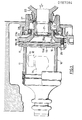
- the lateral output shaft 21 of a differential mechanism 20 carries a grooved end on which is mounted a hub 22 provided with a radial extension shaped as a fixing flange 23.
- the flange 23 has on its periphery threaded holes 24 receiving the assembly screws 25 with the constant velocity joint element 10.
- the hub 22 has a sealing surface on which rests the seal 26 of a bearing 27 screwed into the casing 28 of the mechanism 20.
- the constant velocity joint element 10 has a structure known from the publication FRA-2 502 270.
- the element 10 is constituted by a body 11 in the form of a sheath preferably obtained by forming and of generally three-lobed shape delimiting three raceways for rollers 12 mounted on trunnions 13 provided at the end of a tree 14.
- the sheath is closed by means of an attached bottom shaped as a closing and fixing flange 15 rigidly connected to the hub of the screws 25 to the fixing flange 23 secured to the output shaft 21.
- the face 15a of the closing and fixing flange 15 facing the output shaft 21 has a drive profile, 16 in facial contact with the homologous profile 17 carried by the face 23a of the flange 23 .
- the drive profile 17 is located on the face 18b of a plate 18, the second face 18a of which coincides with the face 23 and the flange 23.
- the face 18a of the plate 18 is rigidly connected for example by means of a weld to the face 23a of the flange 23 with which it is thus merged. Without departing from the scope of the invention, it is obvious that the face 23a can directly carry the drive profile 17.
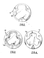
- the drive profile 17 is formed on a boss formed on the face 18b of the plate 18.
- the other profile 16 is formed by an imprint formed on the face 15a of the closure flange 15.
- the closure flange 15 and the plate 18 are identical and the profile 16 of one is adjusted to the profile 17 of the other.
- the impression and the boss carried by the closure flange 15 and by the plate 18 have a configuration with lobes adjustable to the lobed section of the sheath 11.
- the process for the simultaneous production of the profiles 16, 17 is carried out during the process of shaping a sheet metal blank cut to the radial dimensions of the flange 23 in which the passages for the screws 25 located between the various lobes are drilled and at the periphery of the plate 18.
- the process of shaping the plate is also that of the closing and fixing flange 15.
Landscapes
- Engineering & Computer Science (AREA)
- General Engineering & Computer Science (AREA)
- Mechanical Engineering (AREA)
- Chemical & Material Sciences (AREA)
- Combustion & Propulsion (AREA)
- Transportation (AREA)
- Retarders (AREA)
Applications Claiming Priority (2)
| Application Number | Priority Date | Filing Date | Title |
|---|---|---|---|
| FR8418871A FR2574351B1 (fr) | 1984-12-11 | 1984-12-11 | Dispositif de liaison d'un element de joint homocinetique avec un arbre de sortie |
| FR8418871 | 1984-12-11 |
Publications (2)
| Publication Number | Publication Date |
|---|---|
| EP0187084A1 true EP0187084A1 (de) | 1986-07-09 |
| EP0187084B1 EP0187084B1 (de) | 1988-06-01 |
Family
ID=9310450
Family Applications (1)
| Application Number | Title | Priority Date | Filing Date |
|---|---|---|---|
| EP19850402447 Expired EP0187084B1 (de) | 1984-12-11 | 1985-12-10 | Verbindungsvorrichtung zwischen einem homokinetischen Gelenk und einer Ausgangswelle |
Country Status (3)
| Country | Link |
|---|---|
| EP (1) | EP0187084B1 (de) |
| DE (1) | DE3563010D1 (de) |
| FR (1) | FR2574351B1 (de) |
Families Citing this family (1)
| Publication number | Priority date | Publication date | Assignee | Title |
|---|---|---|---|---|
| DE3617983A1 (de) * | 1986-05-28 | 1987-12-03 | Man Nutzfahrzeuge Gmbh | Verbindung von kraftfahrzeugan- bzw. -abtriebswellenteilen |
Citations (3)
| Publication number | Priority date | Publication date | Assignee | Title |
|---|---|---|---|---|
| FR2212879A5 (de) * | 1972-09-27 | 1974-07-26 | Oerlikon Italiana | |
| FR2374180A1 (fr) * | 1976-12-14 | 1978-07-13 | Toyota Motor Co Ltd | Systeme de montage pour arbre d'entrainement de vehicule du type a roues arriere a suspension independante |
| FR2502270A1 (fr) * | 1981-03-19 | 1982-09-24 | Renault | Element de joint homocinetique du type tripode |
-
1984
- 1984-12-11 FR FR8418871A patent/FR2574351B1/fr not_active Expired
-
1985
- 1985-12-10 EP EP19850402447 patent/EP0187084B1/de not_active Expired
- 1985-12-10 DE DE8585402447T patent/DE3563010D1/de not_active Expired
Patent Citations (3)
| Publication number | Priority date | Publication date | Assignee | Title |
|---|---|---|---|---|
| FR2212879A5 (de) * | 1972-09-27 | 1974-07-26 | Oerlikon Italiana | |
| FR2374180A1 (fr) * | 1976-12-14 | 1978-07-13 | Toyota Motor Co Ltd | Systeme de montage pour arbre d'entrainement de vehicule du type a roues arriere a suspension independante |
| FR2502270A1 (fr) * | 1981-03-19 | 1982-09-24 | Renault | Element de joint homocinetique du type tripode |
Also Published As
| Publication number | Publication date |
|---|---|
| DE3563010D1 (en) | 1988-07-07 |
| FR2574351A1 (fr) | 1986-06-13 |
| FR2574351B1 (fr) | 1987-02-13 |
| EP0187084B1 (de) | 1988-06-01 |
Similar Documents
| Publication | Publication Date | Title |
|---|---|---|
| EP2751437B1 (de) | Vorrichtung zum verbinden einer lenksäule mit einem lenkgetriebegehäuse | |
| EP1472475B9 (de) | Differential für fahrzeuge | |
| FR2569145A1 (fr) | Arbre de transmission pour vehicule automobile | |
| EP0647789B1 (de) | Differential-Gehäuse | |
| FR2698928A1 (fr) | Joint universel homocinétique. | |
| FR2470018A1 (fr) | Dispositif pour transmettre un couple entre un arbre d'entrainement, tel que le vilebrequin d'un moteur, et un appareil accessoire, tel qu'un ralentisseur hydrodynamique | |
| EP4185500B1 (de) | Getriebe und mit einem solchen getriebe ausgestattetes kraftfahrzeug | |
| FR2511455A1 (fr) | Joint homocinetique | |
| FR2822916A1 (fr) | Boitier d'un mecanisme de transmission | |
| WO1997042433A1 (fr) | Appareil d'accouplement hydrocinetique a piece d'entrainement de languettes, notamment pour vehicule automobile | |
| EP0187084B1 (de) | Verbindungsvorrichtung zwischen einem homokinetischen Gelenk und einer Ausgangswelle | |
| FR2496795A2 (fr) | Joint universel pour arbre articule | |
| FR2683011A1 (fr) | Dispositif amortisseur de torsion pour appareil de transmission de couple. | |
| EP0057123A2 (de) | Kupplungsmittel für den Rotor einer Einzelschneckenpumpe | |
| EP0034099A1 (de) | Lenksäule für Kraftfahrzeug | |
| EP1591714B1 (de) | Vorrichtung zum Schmieren eines Teils in einem Zusammenbau | |
| FR2916787A1 (fr) | Dispositif de liaison entre un verrou et une serrure de porte de vehicule automobile | |
| EP0819864B1 (de) | Kompakte Synchronisiereinrichtung für ein Zahnradwechselgetriebe, insbesondere für ein Kraftfahrzeug | |
| FR2732087A1 (fr) | Perfectionnements aux differentiels autobloquants | |
| EP0083922B1 (de) | Doppelwirkungsdruckkamm für Zahnradgetriebe mit parallelen Achsen | |
| FR2513204A1 (fr) | Direction assistee | |
| FR2786451A1 (fr) | Dispositif pour transmettre des couples de freinage pour vehicules automobiles | |
| EP0260196A1 (de) | Kupplungseinrichtung zwischen einer Motorenanlage und einer Wagenantriebswelle | |
| FR2839750A1 (fr) | Dispositif d'entrainement d'une pompe a injection diesel | |
| EP0969175A1 (de) | Getriebemotor zum Antrieb eines Kraftfahrzeug-Funktionselements |
Legal Events
| Date | Code | Title | Description |
|---|---|---|---|
| PUAI | Public reference made under article 153(3) epc to a published international application that has entered the european phase |
Free format text: ORIGINAL CODE: 0009012 |
|
| 17P | Request for examination filed |
Effective date: 19851213 |
|
| AK | Designated contracting states |
Kind code of ref document: A1 Designated state(s): BE DE GB IT |
|
| 17Q | First examination report despatched |
Effective date: 19871109 |
|
| GRAA | (expected) grant |
Free format text: ORIGINAL CODE: 0009210 |
|
| AK | Designated contracting states |
Kind code of ref document: B1 Designated state(s): BE DE GB IT |
|
| ITF | It: translation for a ep patent filed | ||
| REF | Corresponds to: |
Ref document number: 3563010 Country of ref document: DE Date of ref document: 19880707 |
|
| GBT | Gb: translation of ep patent filed (gb section 77(6)(a)/1977) | ||
| PLBE | No opposition filed within time limit |
Free format text: ORIGINAL CODE: 0009261 |
|
| STAA | Information on the status of an ep patent application or granted ep patent |
Free format text: STATUS: NO OPPOSITION FILED WITHIN TIME LIMIT |
|
| 26N | No opposition filed | ||
| PG25 | Lapsed in a contracting state [announced via postgrant information from national office to epo] |
Ref country code: BE Effective date: 19891231 |
|
| BERE | Be: lapsed |
Owner name: REGIE NATIONALE DES USINES RENAULT Effective date: 19891231 |
|
| PGFP | Annual fee paid to national office [announced via postgrant information from national office to epo] |
Ref country code: DE Payment date: 19900907 Year of fee payment: 6 |
|
| PGFP | Annual fee paid to national office [announced via postgrant information from national office to epo] |
Ref country code: GB Payment date: 19901119 Year of fee payment: 6 |
|
| ITTA | It: last paid annual fee | ||
| PG25 | Lapsed in a contracting state [announced via postgrant information from national office to epo] |
Ref country code: GB Effective date: 19911210 |
|
| GBPC | Gb: european patent ceased through non-payment of renewal fee | ||
| PG25 | Lapsed in a contracting state [announced via postgrant information from national office to epo] |
Ref country code: DE Effective date: 19920901 |