EP0187086A1 - Verfahren zur Freund-oder-Feind-Abfrage und Vorrichtung zur Durchführung dieses Verfahrens - Google Patents
Verfahren zur Freund-oder-Feind-Abfrage und Vorrichtung zur Durchführung dieses Verfahrens Download PDFInfo
- Publication number
- EP0187086A1 EP0187086A1 EP85402453A EP85402453A EP0187086A1 EP 0187086 A1 EP0187086 A1 EP 0187086A1 EP 85402453 A EP85402453 A EP 85402453A EP 85402453 A EP85402453 A EP 85402453A EP 0187086 A1 EP0187086 A1 EP 0187086A1
- Authority
- EP
- European Patent Office
- Prior art keywords
- word
- modulation
- dates
- keyword
- coding
- Prior art date
- Legal status (The legal status is an assumption and is not a legal conclusion. Google has not performed a legal analysis and makes no representation as to the accuracy of the status listed.)
- Granted
Links
- 238000000034 method Methods 0.000 title claims abstract description 20
- 125000004122 cyclic group Chemical group 0.000 claims abstract description 8
- 230000003071 parasitic effect Effects 0.000 claims abstract description 3
- 230000015654 memory Effects 0.000 claims description 18
- 238000010200 validation analysis Methods 0.000 claims description 14
- 238000013518 transcription Methods 0.000 claims description 6
- 230000035897 transcription Effects 0.000 claims description 6
- 230000000712 assembly Effects 0.000 claims description 4
- 238000000429 assembly Methods 0.000 claims description 4
- 230000004044 response Effects 0.000 claims description 3
- 230000015572 biosynthetic process Effects 0.000 claims 1
- 230000006870 function Effects 0.000 claims 1
- 238000004364 calculation method Methods 0.000 description 8
- 238000004891 communication Methods 0.000 description 4
- 230000005540 biological transmission Effects 0.000 description 3
- 238000010586 diagram Methods 0.000 description 2
- 238000012545 processing Methods 0.000 description 2
- 230000002123 temporal effect Effects 0.000 description 2
- 241000270730 Alligator mississippiensis Species 0.000 description 1
- 230000001427 coherent effect Effects 0.000 description 1
- 238000001514 detection method Methods 0.000 description 1
- 238000005516 engineering process Methods 0.000 description 1
- 239000011159 matrix material Substances 0.000 description 1
- 238000012544 monitoring process Methods 0.000 description 1
- 238000012360 testing method Methods 0.000 description 1
- 230000001960 triggered effect Effects 0.000 description 1
Images


Classifications
-
- G—PHYSICS
- G01—MEASURING; TESTING
- G01S—RADIO DIRECTION-FINDING; RADIO NAVIGATION; DETERMINING DISTANCE OR VELOCITY BY USE OF RADIO WAVES; LOCATING OR PRESENCE-DETECTING BY USE OF THE REFLECTION OR RERADIATION OF RADIO WAVES; ANALOGOUS ARRANGEMENTS USING OTHER WAVES
- G01S17/00—Systems using the reflection or reradiation of electromagnetic waves other than radio waves, e.g. lidar systems
- G01S17/74—Systems using reradiation of electromagnetic waves other than radio waves, e.g. IFF, i.e. identification of friend or foe
-
- G—PHYSICS
- G01—MEASURING; TESTING
- G01S—RADIO DIRECTION-FINDING; RADIO NAVIGATION; DETERMINING DISTANCE OR VELOCITY BY USE OF RADIO WAVES; LOCATING OR PRESENCE-DETECTING BY USE OF THE REFLECTION OR RERADIATION OF RADIO WAVES; ANALOGOUS ARRANGEMENTS USING OTHER WAVES
- G01S13/00—Systems using the reflection or reradiation of radio waves, e.g. radar systems; Analogous systems using reflection or reradiation of waves whose nature or wavelength is irrelevant or unspecified
- G01S13/74—Systems using reradiation of radio waves, e.g. secondary radar systems; Analogous systems
- G01S13/76—Systems using reradiation of radio waves, e.g. secondary radar systems; Analogous systems wherein pulse-type signals are transmitted
- G01S13/78—Systems using reradiation of radio waves, e.g. secondary radar systems; Analogous systems wherein pulse-type signals are transmitted discriminating between different kinds of targets, e.g. IFF-radar, i.e. identification of friend or foe
Definitions
- the invention relates to friend-enemy interrogation for the establishment of radio communication links or the identification of an external system, generally a vehicle or an aircraft.
- the modulation of a light wave such as the laser beam is preferably used, which gives the link a high degree of discretion and protection against interference.
- IFF from the Anglo-Saxon designation Identification of Friend and Foe.
- the complete IFF link requires an interrogator and an answering machine, and is established using a keyword.
- a laser generator is used in the interrogator to produce a first light wave. This wave can be modulated either in frequency or in amplitude. Frequency modulation is carried out on either side of an average value F, amplitude modulation is carried out by the presence or absence of pulses.
- a laser transmitter modulator receives from a control and coding circuit a modulation signal translating the code or the keyword to be transmitted.
- the same control and coding circuit is used to code a monitoring keyword.
- a laser receiver and a demodulator supply to a correlation circuit the keyword received to compare it to the keyword of the responder. Depending on this comparison, the keyword is validated or not. The result of this comparison is communicated to the interrogator, for example by radio, to establish the final communication.
- Amplitude modulation has always been the most used because it is easy to implement. But it has two major drawbacks. The first is the ambiguity of decision, consecutive by example to large fluctuations in amplitude. An insufficient pulse amplitude may be mistaken for zero. The second drawback is the low information capacity of the corresponding messages. This last point is particularly important in an IFF connection where the duration of the message must be short.
- Frequency modulation consists in transmitting two or more recurrence frequencies characterizing a coding structure. But for a laser of wavelength equal to 1.06 microns, the number of recurrences is limited. The capacity of the message therefore remains low.
- the security measures imposed are such that these transmission techniques and the coding means used do not ensure a sufficient level of discretion.
- the object of the invention is to develop a linking system which allows the use of a large number of different keywords, and the coding system of which significantly reduces the risks of interception and decoding of the keyword. .
- a first feature of the invention consists in using the position modulation known as MP, or PPM (according to the Anglo-Saxon designation Pulse Position Modulation).
- a second feature consists in implementing a coding method using a cyclic code and decoding by correlation of the keyword without a fixed reference pulse.
- Another object of the invention is a friend-enemy interrogation system by modulation of a wave
- an interrogator assembly comprising a transmitting part composed of a coding assembly developing a control signal characteristic of a keyword to be transmitted, a generator developing a modulation signal from the coded signal, and a transmitter controlled by the signal and transmitting the coded keyword modulating said wave, and a receiving part, and secondly a responder unit comprising a coding unit producing a reference signal identical to the coded signal, means for correlating and validating the received word with respect to the reference word, and a transmitting part for sending a response to the receiving part of the interrogator, the system being characterized in that the modulation of the wave is a position modulation, in that said coding assemblies consist of a device for displaying the keyword having a determined number d e bits, means for transcoding this initial keyword coded into a final keyword having a different number of bits using a cyclic code, and a circuit for temporal transcription of
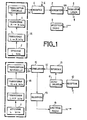
- the friend-enemy interrogation system includes an interrogator assembly and a responder assembly (fig. 1). Both in the interrogator set and in the responder set, the same IA or IB coding set is used. It is used, in the case of the interrogator to control the emission of a coded keyword, and for the responder to code the reference keyword to compare the latter with the various messages received, in this case a coded word sent. .
- the signal produced by the coding unit IA of the interrogator represents a coded keyword and is called control signal SC. It is applied via an interface 6 to a generator 7 which generates a modulation signal SM from the signal SC and which controls a modulator-emitter sub-assembly 8.
- the latter by modulation of a light wave and more particularly of a laser wave, emits the code word.
- a receiving part 9, which can be a radio receiver, can be used to then receive a good reception message sent from the answering machine.
- the signal produced by the coding unit 1B of the answering machine represents a local word and is called reference signal SR. It is applied to a correlation circuit 12.
- a receiver 10 compatible with the transmitter 8, receives the code word.
- a demodulator 11 receives the output of the receiver 10 and transmits the received word demodulated via an interface 15 to the correlation circuit 12.
- the latter includes processing circuits which compare the reference signal SR with the output SI of the 'interface 15 which delivers the messages received and theoretically the keyword emitted by the interro gator.
- a validation circuit 13 receives the result of the correlation and determines according to the predetermined criteria whether the word received must be validated or not.
- a transmitting part 14, for example a radio transmitter controlled by the validation, can be used to send a response message to the interrogator and possibly establish the final communication between the two stations.
- the principle of the transcoding sets lA and 1B is as follows: starting from a significant word represented in octal by the keyword, a transcoding is carried out making it possible to obtain a binary sequence having a high entropy therefore, for systems foreign to communication, a great degree of uncertainty as to its detection.
- a display device 2 allows the operator to display the keyword of an initial number L of bits, and to code this word in binary.
- the display can be carried out by coding wheels defining an octal word.
- Transcoding means 3 and 4 receiving the output of the display device, transform this initial word of L bits into a final word of N bits which makes it possible to develop the control signal SC.
- These transcoding means are divided into two transcoding circuits.
- a first transcoding circuit 3, called random transforms the word to be coded from L bits into a word of M bits. The purpose of this circuit is to make the word coherent with the coding used.
- a second transcoding circuit 4 called linear, performs the actual coding of the word of M bits into a word of N bits according to the code used.
- This circuit implements a cyclic linear code for data transmission.
- the Golay code is used which transcribes a 12-bit word (M) into a 23-bit word (N) and which can be found in detail in Peterson and Weldon's "Error Correcting Codes".
- M 12-bit word
- N 23-bit word
- Peterson and Weldon's "Error Correcting Codes” A twenty-fourth bit is added in order to simplify the correspondence between the coding in position, discussed below, and the binary code.
- a time transcription circuit 5 which receives the 24-bit word and calculates the D dates (T 1 to TD) established with respect to the date T 0 of the first pulse. It delivers the control signal SC which is digital and which represents these dates.
- control interface circuit 6 for example a programmable counter, receives a clock signal H, and the control signal SC from the time transcription circuit 5 translating the D dates characteristic of the coded keyword . It transforms this control signal SC into a modulation signal SM.
- the principle of this position modulation is as follows.
- the position of each pulse is identified at each recurrence with respect to an average position (M 1 , M 2 ). This location is carried out within 2.P intervals located on either side of the average position.
- Optimal binary coding assumes that P is a power of 2.
- the average positions are separated from each other by a recurrence interval R.
- the constraints imposed on the message IFF are mainly the low value of the acquisition time and the reliability of the link. This is increased if an error detector or corrector code is used, the implementation of which is relatively easy, in order to reduce the volume and the calculation time.
- the choice of coding, in this case the Golay code is therefore a compromise between a structure of sufficient length to use the largest number of different keywords, and the shortest possible acquisition time.
- the number of modulation positions is eight, the number of useful pulses D per coded word is four, plus a reference pulse.
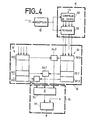
- FIG. 3 The embodiment of the coding assembly shown in FIG. 3 is an example. It illustrates the various operations carried out in this system. A realization with microprocessor can be envisaged to carry out the various calculations.
- the R and Q values are fixed in advance according to the coding, the technology used and the wavelength of the laser. It can use a second shift register 24 receiving in series the output of the first register 22. It delivers in parallel the 24 bits which are taken into account three by three by a calculation circuit 25 which performs the calculation of T .. A summator 26 is then used to add the value T 0 .
- the demodulator 11 may include a cyclic hour counter 30 controlled by a clock signal H identical to that used in the interrogator. This counter is triggered by the first pulse received from the laser receiver 10. Its output is connected to a memory 33, the output of which is also controlled by the receiver. Therefore the output of memory 33 provides the dates T ' 1 , T' 2 , .... T D of the pulses detected by the receiver, and this with respect to the date of the first pulse T 0 .
- the correlation circuit 12 proceeds digitally. It receives, in the form of dates, on the one hand the coded reference keyword, and delivered via the transcoding assembly 1 of the answering machine, and on the other hand the word detected via the 'interface 15.
- the local word displayed theoretically identical to that received, reaches it in the form of the dates T 0 , T 1 , . .
- These dates are stored in a first memory set 31. This set can consist of several shift registers, one for each bit, representing the dates.
- the first memory 31.0 consists of the first cell in each of the registers and contains the first date T 0 .
- the second memory 31.1 contains the second date T 1 , the last memory 31.D contains the last date T D.
- T ' D of the received word are stored analogously to the dates of the local word, in a second memory assembly 32 which can be constituted by several shift registers.
- the dates T ' D , T' 1 , .... T ' D are respectively stored in memories 32.0, 32.1, ...., 32.D analogous to memories 31.0 to 31.D.
- a number D + 1 of comparators equal to the number of dates, 34.0, 34.1, ...., 34.D, is used to compare the contents of the memory sets 31 and 32.
- the first comparator 34.0 compares the contents of the two first memories 31.0 and 32.0, the second 34.1 those of the second memories 31.1 and 32.1, and so on, the last 34.D those of the last memories 31.D and 32.D. Therefore each date T0, T 1 , .... T D characterizing the displayed word is compared with that T ' 0 , T' 1 , Across T ' D of the same order of the pulses received.
- the output of the comparator delivers a signal equal to 1, if they differ the signal is equal to 0.
- the validation circuit 13 receives the output of each comparator 34.0 to 34.D in a summing circuit 36.
- the output of this summing device is connected to the input of a threshold comparator 37. If the strict identity between the word is required displayed and the word received, the threshold is fixed equal to the number D of dates of the word displayed. By displaying a threshold S of D-1, an error concerning the transmission of the coded word is tolerated. It is thus possible to validate the word received with a probability compatible with the performances required of the system.
- the output of this threshold comparator 37 constitutes the output of the validation circuit 13 and makes it possible to control the transmitter 14.
- the invention provides an improvement of the correlation process to limit the time for recognizing the word received and to compensate for any instability of the clock, both in the interrogator and in the responder.
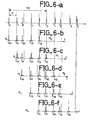
- the intervals delivered by the transcoding set 1B of the answering machine and characterizing the reference code word can be shown diagrammatically by a rectangular signal, represented in fig. 5b, the width of the slots of which is linked to the stability of the clock.
- Fig.5a shows the diagram of the corresponding dates in relation to the intervals of fig.5b.
- the D intervals 1 constitute a table of 4 rows and 2 columns, characterized by the number which is that of the reference pulse.
- a particularity of the improvement of the proposed process consists in randomly taking any one of the dates T 0 to T D emitted as reference pulse.
- a number D + 1 of similar tables is established in each of which the intervals corresponding to each pulse are entered.
- the time reference pulse is different for each table. It characterizes the table M j by its serial number j in the sequence constituted by the local word displayed, and each of the other pulses is dated with respect to it, assuming that the local word has been repeated once.
- Each table therefore contains the minimum and maximum instants of arrival of the pulses to be received.
- the table M 2 contains the intervals I 12 , I 22 , I 32 , I 42 , and corresponding relatively to the dates T 1 , T 2 , T 3 , T 4 .
- the word was repeated once, the dates being shifted on average by four times the average recurrence interval R.
- the intervals are positioned with respect to the corresponding pulses, the first date T o being the reference. They constitute the intervals of table M.
- the intervals of the tables M 1 , M 29 M 39 M 4, respectively, are always positioned relative to their corresponding dates. The word being repeated at least once, if the coded keyword is only received by the responder unit from the pulse T., the latter can be taken as a reference for dating the following ones.
- the sequence of the first dates received corresponds to one of the tables.
- Spurious pulses can mix, upon reception, with the pulses constituting the received word.
- the correlation method according to the invention can make it possible to remedy this drawback in the following manner. This possibility requires only memories and a little additional software.
- a modulo R dating of all the received pulses is made from the first received pulse.
- Each pulse is then characterized by its recurrence number j and by the symbol P i of its relative modulation position i with respect to the instant corresponding to the average recurrence.
- Relative dating is between This gives a certain number of dating groups normally equal to the number D of useful pulses received.
- a group can contain a number X of pulses including X - 1 spurious pulses.
- the first pulse is then taken as the origin of the times and a sequence of time values is compared, each of them being taken from a different group. The prepositioned values from the comparison tables are used. After exhaustion of all possible combinations, if there has not been validation, the second pulse received is then taken as the origin of the times and the cycle is restarted.
- the course of the correlation is as follows.
- We then increment i, and the two tenth date T 20 of the sequence is compared to its corresponding interval I 20 . If the date T 10 does not belong to I 10 , j is incremented.
- the signal processing assembly provided by the coding assemblies, and the correlation and validation calculations in the answering machine, can be performed by a microprocessor system.
Landscapes
- Engineering & Computer Science (AREA)
- Radar, Positioning & Navigation (AREA)
- Remote Sensing (AREA)
- Physics & Mathematics (AREA)
- Electromagnetism (AREA)
- Computer Networks & Wireless Communication (AREA)
- General Physics & Mathematics (AREA)
- Radar Systems Or Details Thereof (AREA)
Applications Claiming Priority (2)
| Application Number | Priority Date | Filing Date | Title |
|---|---|---|---|
| FR8419197 | 1984-12-14 | ||
| FR8419197A FR2574948B1 (fr) | 1984-12-14 | 1984-12-14 | Procede d'interrogation ami-ennemi et systeme utilisant ce procede |
Publications (2)
| Publication Number | Publication Date |
|---|---|
| EP0187086A1 true EP0187086A1 (de) | 1986-07-09 |
| EP0187086B1 EP0187086B1 (de) | 1990-06-27 |
Family
ID=9310631
Family Applications (1)
| Application Number | Title | Priority Date | Filing Date |
|---|---|---|---|
| EP85402453A Expired - Lifetime EP0187086B1 (de) | 1984-12-14 | 1985-12-10 | Verfahren zur Freund-oder-Feind-Abfrage und Vorrichtung zur Durchführung dieses Verfahrens |
Country Status (4)
| Country | Link |
|---|---|
| US (1) | US4814769A (de) |
| EP (1) | EP0187086B1 (de) |
| DE (1) | DE3578459D1 (de) |
| FR (1) | FR2574948B1 (de) |
Cited By (9)
| Publication number | Priority date | Publication date | Assignee | Title |
|---|---|---|---|---|
| EP0254197A1 (de) * | 1986-07-17 | 1988-01-27 | Alcatel SEL Aktiengesellschaft | Einrichtung zur Freund-Feind-Identifikation |
| US5170168A (en) * | 1986-07-17 | 1992-12-08 | Standard Elektrik Lorenz Ag | Identification of friend from foe device |
| GB2260665A (en) * | 1989-11-09 | 1993-04-21 | Stc Plc | Communications using fibre optics and radio |
| FR2691862A1 (fr) * | 1992-05-27 | 1993-12-03 | Intertechnique Sa | Répondeur d'identification et dispositif d'identification à distance comportant un tel répondeur. |
| FR2697702A1 (fr) * | 1992-10-24 | 1994-05-06 | British Aerospace | Ensemble de communications optiques. |
| EP0614093A1 (de) * | 1993-03-05 | 1994-09-07 | Thomson-Csf | Identifizierungssystem mit hohem Unterscheidungsvermögen |
| EP0859243A1 (de) * | 1997-02-18 | 1998-08-19 | Oerlikon Contraves Ag | Laseridentifikationssystem |
| US5966226A (en) * | 1996-10-11 | 1999-10-12 | Oerlikon-Contraves Ag | Combat communication system |
| US6174169B1 (en) | 1997-11-27 | 2001-01-16 | Oerlikon Contraves Ag | Laser identification system |
Families Citing this family (19)
| Publication number | Priority date | Publication date | Assignee | Title |
|---|---|---|---|---|
| US5001751A (en) * | 1989-04-07 | 1991-03-19 | Allied-Signal Inc. | Mode 4 reply decoder |
| US5375008A (en) * | 1991-07-17 | 1994-12-20 | Electronic Warfare Associates, Inc. | Systems for distinguishing between friendly ground targets and those of a foe |
| CA2055198A1 (en) * | 1991-11-08 | 1993-05-09 | Raymond Carbonneau | Optical identification friend-or-foe |
| CA2129024A1 (en) * | 1992-04-01 | 1993-10-14 | John R. Wootton | Beam steered laser iff system |
| US5280287A (en) * | 1992-06-30 | 1994-01-18 | The United States Of America As Represented By The Secretary Of The Navy | Coded identification and positioning system |
| US5396243A (en) * | 1992-12-23 | 1995-03-07 | The United States Of America As Represented By The Secretary Of The Air Force | Infrared laser battlefield identification beacon |
| US5299227A (en) * | 1993-04-13 | 1994-03-29 | American Electronics, Inc. | Individual beacon identification system |
| US5822430A (en) * | 1996-11-20 | 1998-10-13 | Technical Communications Corporation | System for encoding encryption/decryption information into IFF challenges |
| US6166679A (en) * | 1999-01-13 | 2000-12-26 | Lemelson Jerome H. | Friend or foe detection system and method and expert system military action advisory system and method |
| FR2829584B1 (fr) * | 2001-09-07 | 2003-12-05 | Thales Sa | Procede et dispositif permettant de generer plusieurs canaux dans un systeme de type iff |
| US8224189B1 (en) | 2007-02-02 | 2012-07-17 | Sunlight Photonics Inc. | Retro-directive target for free-space optical communication and method of producing the same |
| RU2353892C2 (ru) * | 2007-02-26 | 2009-04-27 | Владимир Анатольевич Клевакин | Способ определения принадлежности наземной техники к стороне-участнице военных действий |
| US8269664B2 (en) * | 2007-09-20 | 2012-09-18 | Lockheed Martin Corporation | Covert long range positive friendly identification system |
| CN101822127A (zh) * | 2007-10-12 | 2010-09-01 | 皇家飞利浦电子股份有限公司 | 使用反向反射器检测经过编码的光 |
| RU2404403C1 (ru) * | 2009-11-30 | 2010-11-20 | Открытое акционерное общество "Авангард" | Комплексный способ определения принадлежности наземной техники и военнослужащих к стороне - участнице военных действий |
| RU2449314C2 (ru) * | 2010-02-19 | 2012-04-27 | Владимир Анатольевич Клевакин | Способ определения принадлежности наземной техники к стороне - участнице военных действий по ее изображению на экране тепловизора |
| US9602203B2 (en) * | 2015-03-24 | 2017-03-21 | The United States Of America As Represented By The Secretary Of The Navy | Methods and systems for identification and communication using free space optical systems including wearable systems |
| US10371792B2 (en) * | 2015-07-17 | 2019-08-06 | Raytheon Command And Control Solutions Llc | System and method for providing remote target identification using radiofrequency identification |
| IL310912A (en) * | 2024-02-15 | 2025-09-01 | Elbit Systems Ew And Sigint Elisra Ltd | Electronic warfare system and method |
Citations (1)
| Publication number | Priority date | Publication date | Assignee | Title |
|---|---|---|---|---|
| DE3113154A1 (de) * | 1981-04-01 | 1982-12-02 | Precitronic Gesellschaft für Feinmechanik und Electronic mbH, 2000 Hamburg | "system zur optronischen dateneingabe in laser-nachrichtengeraeten" |
Family Cites Families (6)
| Publication number | Priority date | Publication date | Assignee | Title |
|---|---|---|---|---|
| DE1961914C1 (de) * | 1969-12-10 | 1984-05-24 | Siemens AG, 1000 Berlin und 8000 München | Abfrage-Antwort-System fuer Sekundaerradargeraete mit Freund-Feind-Identifizierung |
| US4194201A (en) * | 1970-09-23 | 1980-03-18 | Siemens Aktiengesellschaft | Interrogator-responsor system |
| GB2052908A (en) * | 1979-05-23 | 1981-01-28 | Secr Defence | Radar transponders |
| US4384288A (en) * | 1980-12-31 | 1983-05-17 | Walton Charles A | Portable radio frequency emitting identifier |
| US4427980A (en) * | 1981-10-13 | 1984-01-24 | Motorola, Inc. | Encoder for transmitted message activation code |
| DE3379767D1 (en) * | 1982-09-02 | 1989-06-01 | British Telecomm | Optical communication |
-
1984
- 1984-12-14 FR FR8419197A patent/FR2574948B1/fr not_active Expired
-
1985
- 1985-12-06 US US06/805,743 patent/US4814769A/en not_active Expired - Fee Related
- 1985-12-10 DE DE8585402453T patent/DE3578459D1/de not_active Expired - Fee Related
- 1985-12-10 EP EP85402453A patent/EP0187086B1/de not_active Expired - Lifetime
Patent Citations (1)
| Publication number | Priority date | Publication date | Assignee | Title |
|---|---|---|---|---|
| DE3113154A1 (de) * | 1981-04-01 | 1982-12-02 | Precitronic Gesellschaft für Feinmechanik und Electronic mbH, 2000 Hamburg | "system zur optronischen dateneingabe in laser-nachrichtengeraeten" |
Cited By (13)
| Publication number | Priority date | Publication date | Assignee | Title |
|---|---|---|---|---|
| US5170168A (en) * | 1986-07-17 | 1992-12-08 | Standard Elektrik Lorenz Ag | Identification of friend from foe device |
| EP0254197A1 (de) * | 1986-07-17 | 1988-01-27 | Alcatel SEL Aktiengesellschaft | Einrichtung zur Freund-Feind-Identifikation |
| GB2260665A (en) * | 1989-11-09 | 1993-04-21 | Stc Plc | Communications using fibre optics and radio |
| GB2260665B (en) * | 1989-11-09 | 1993-12-15 | Stc Plc | Communications |
| FR2691862A1 (fr) * | 1992-05-27 | 1993-12-03 | Intertechnique Sa | Répondeur d'identification et dispositif d'identification à distance comportant un tel répondeur. |
| US5485301A (en) * | 1992-10-24 | 1996-01-16 | British Aerospace Plc | Optical communications |
| FR2697702A1 (fr) * | 1992-10-24 | 1994-05-06 | British Aerospace | Ensemble de communications optiques. |
| EP0614093A1 (de) * | 1993-03-05 | 1994-09-07 | Thomson-Csf | Identifizierungssystem mit hohem Unterscheidungsvermögen |
| FR2702280A1 (fr) * | 1993-03-05 | 1994-09-09 | Thomson Csf | Système d'identification à haut pouvoir discriminant. |
| US5966226A (en) * | 1996-10-11 | 1999-10-12 | Oerlikon-Contraves Ag | Combat communication system |
| EP0859243A1 (de) * | 1997-02-18 | 1998-08-19 | Oerlikon Contraves Ag | Laseridentifikationssystem |
| US6439892B1 (en) | 1997-02-18 | 2002-08-27 | Oerlikon Contraves Ag | Laser identification system |
| US6174169B1 (en) | 1997-11-27 | 2001-01-16 | Oerlikon Contraves Ag | Laser identification system |
Also Published As
| Publication number | Publication date |
|---|---|
| US4814769A (en) | 1989-03-21 |
| FR2574948B1 (fr) | 1987-01-16 |
| DE3578459D1 (de) | 1990-08-02 |
| FR2574948A1 (fr) | 1986-06-20 |
| EP0187086B1 (de) | 1990-06-27 |
Similar Documents
| Publication | Publication Date | Title |
|---|---|---|
| EP0187086B1 (de) | Verfahren zur Freund-oder-Feind-Abfrage und Vorrichtung zur Durchführung dieses Verfahrens | |
| EP0505223B1 (de) | Vorrichtung zur digitalen Datenübertragung über eine Leitung des Stromnetzes | |
| US20180367223A1 (en) | Systems and methods for concealing waveform properties | |
| CA2259870C (fr) | Procede de communication d'informations et application de ce procede a un systeme de telereleve de compteurs | |
| EP2974054B1 (de) | System und verfahren für kommunikation mit niedriger datenrate über einen trägerstrom | |
| EP0142427B1 (de) | Digitales Datenübertragungssystem unter Verwendung einer kohärenten Lichtwellenmodulation | |
| CA2099700A1 (fr) | Procede et dispositif d'amelioration de la probabilite de validite des codes des reponses de radar secondaire | |
| FR2775854A1 (fr) | Procede et dispositif de transmission et de reception de donnees, notamment dans un systeme mobile de telecommunications par satellite | |
| EP0235477B1 (de) | Störunempfindliches Verfahren und Einrichtung zur Funkübertragung von kodierten Informationen | |
| EP3488535B1 (de) | Verfahren zur übertragung einer nachricht mit intra-nachrichten-frequenzsprüngen durch ein endgerät eines schlitzbasierten zugriffskommunikationssystems | |
| EP3949168A1 (de) | Verfahren und vorrichtung zum empfang einer ads-b-nachricht über einen satelliten | |
| FR2700226A1 (fr) | Système de modulation par codage en treillis. | |
| EP0097579B1 (de) | Funkverbindungssystem nach dem Frequenzsprungverfahren mit Redundanz zwischen den einzelnen Frequenzstufen | |
| CH640678A5 (fr) | Procede et installation de transmission simultanee d'une onde basse frequence et d'un signal numerique mic. | |
| EP3539253A1 (de) | Verfahren und vorrichtung zum senden von verschlüsselten daten, verfahren und vorrichtung zum extrahieren von daten | |
| EP0037770B1 (de) | System zur paketweisen Übertragung digitaler Daten unter Verwendung eines besonderen Typs von Synchronisationsworten | |
| EP0994580B1 (de) | Übertragungsverfahren in einem Funkkommunikationssystem mit Vielfachzugriff | |
| EP0028188B1 (de) | Bakensystem zur etappenweisen Informationsübertragung | |
| WO2020127496A1 (fr) | Procédés et dispositifs pour l'émission et pour l'estimation de l'instant d'arrivée d'une séquence de bits | |
| WO2002098092A1 (fr) | Procede de codage | |
| WO2015150488A1 (fr) | Procede de communication radio de donnees numeriques dans un environnement bruite | |
| FR2843504A1 (fr) | Procede et systeme pour la determination aveugle de caracteristiques de systeme a sauts de frequence et pour la synchronisation avec celui-ci. | |
| FR2505110A1 (en) | Redundant digital information transmission system - uses six frequency pulses in coded sequence to be received within time windows in order to reduce possibility of noise interference | |
| FR2667463A1 (fr) | Systeme d'emission-reception de trames numeriques a un debit autorisant une insertion d'elements binaires additionnels pouvant constituer soit un code correcteur d'erreur, soit des elements binaires d'information supplementaires. | |
| FR2649271A1 (fr) | Procede pour la transmission de donnees a sauts de frequence sur canal radio a faible taux d'ouverture et dispositif de reception correspondant |
Legal Events
| Date | Code | Title | Description |
|---|---|---|---|
| PUAI | Public reference made under article 153(3) epc to a published international application that has entered the european phase |
Free format text: ORIGINAL CODE: 0009012 |
|
| AK | Designated contracting states |
Kind code of ref document: A1 Designated state(s): DE GB IT |
|
| 17P | Request for examination filed |
Effective date: 19861217 |
|
| 17Q | First examination report despatched |
Effective date: 19880909 |
|
| RAP3 | Party data changed (applicant data changed or rights of an application transferred) |
Owner name: THOMSON-CSF |
|
| GRAA | (expected) grant |
Free format text: ORIGINAL CODE: 0009210 |
|
| AK | Designated contracting states |
Kind code of ref document: B1 Designated state(s): DE GB IT |
|
| ITF | It: translation for a ep patent filed | ||
| GBT | Gb: translation of ep patent filed (gb section 77(6)(a)/1977) | ||
| REF | Corresponds to: |
Ref document number: 3578459 Country of ref document: DE Date of ref document: 19900802 |
|
| PLBI | Opposition filed |
Free format text: ORIGINAL CODE: 0009260 |
|
| 26 | Opposition filed |
Opponent name: SIEMENS AKTIENGESELLSCHAFT, BERLIN UND MUENCHEN Effective date: 19910322 |
|
| ITTA | It: last paid annual fee | ||
| PLBN | Opposition rejected |
Free format text: ORIGINAL CODE: 0009273 |
|
| STAA | Information on the status of an ep patent application or granted ep patent |
Free format text: STATUS: OPPOSITION REJECTED |
|
| 27O | Opposition rejected |
Effective date: 19930719 |
|
| PGFP | Annual fee paid to national office [announced via postgrant information from national office to epo] |
Ref country code: GB Payment date: 19941121 Year of fee payment: 10 Ref country code: DE Payment date: 19941121 Year of fee payment: 10 |
|
| PG25 | Lapsed in a contracting state [announced via postgrant information from national office to epo] |
Ref country code: GB Effective date: 19951210 |
|
| GBPC | Gb: european patent ceased through non-payment of renewal fee |
Effective date: 19951210 |
|
| PG25 | Lapsed in a contracting state [announced via postgrant information from national office to epo] |
Ref country code: DE Effective date: 19960903 |