EP0187089A1 - Vorrichtung zur Messung der Flussdruckcharakteristiken eines Gases das durch eine Probe eines zweiseitigen Produktes fliesst - Google Patents
Vorrichtung zur Messung der Flussdruckcharakteristiken eines Gases das durch eine Probe eines zweiseitigen Produktes fliesst Download PDFInfo
- Publication number
- EP0187089A1 EP0187089A1 EP85402464A EP85402464A EP0187089A1 EP 0187089 A1 EP0187089 A1 EP 0187089A1 EP 85402464 A EP85402464 A EP 85402464A EP 85402464 A EP85402464 A EP 85402464A EP 0187089 A1 EP0187089 A1 EP 0187089A1
- Authority
- EP
- European Patent Office
- Prior art keywords
- sample
- output
- flow
- vacuum
- pump
- Prior art date
- Legal status (The legal status is an assumption and is not a legal conclusion. Google has not performed a legal analysis and makes no representation as to the accuracy of the status listed.)
- Granted
Links
Images


Classifications
-
- G—PHYSICS
- G01—MEASURING; TESTING
- G01N—INVESTIGATING OR ANALYSING MATERIALS BY DETERMINING THEIR CHEMICAL OR PHYSICAL PROPERTIES
- G01N15/00—Investigating characteristics of particles; Investigating permeability, pore-volume or surface-area of porous materials
- G01N15/08—Investigating permeability, pore-volume, or surface area of porous materials
- G01N15/082—Investigating permeability by forcing a fluid through a sample
- G01N15/0826—Investigating permeability by forcing a fluid through a sample and measuring fluid flow rate, i.e. permeation rate or pressure change
Definitions
- the subject of the present invention is an apparatus for measuring the flow-pressure characteristic of a gas passing through a two-sided product sample comprising a sample holder arranged so that one of the faces of the sample is subjected to atmospheric pressure, a pump for applying a vacuum to the other face of the sample, a sensor for measuring said vacuum a sensor for measuring the flow of gas through the sample which results from said vacuum, a setpoint signal generator and means for comparing the output of one of the two sensors and the output of the setpoint signal generator.
- Such a device is in particular used to measure the air permeability of materials used as cigarette paper, or sheathing for a filter, in conformity for example with the international standard ISO 2965 or with the French standard NF V37-010.
- Permeability is the ratio of air flow (volume per unit time) per unit area of the sample to the pressure difference across that sample.
- British patent application No. 2,094,986A describes an apparatus of the above type, in which, however, there is neither a setpoint signal generator, nor means for comparing the output of one of the sensors and the setpoint signal generator output.
- this device means are provided for varying the air flow rate through the sample, constituted in particular by a battery of constant flow devices mounted in parallel, and connecting the sample holder to the pump.
- a valve In series with each device, a valve is mounted and the nominal values of the flows likely to pass through each of the branches are in geometric progression: the first device, when in service, is necessarily traversed by a flow of 1 liter per minute, the second by a flow of 2 liters per minute, the third by a flow of 4 liters per minute and so on.
- each permeability measurement is made under specified conditions of depression, for example 0.25 and 1 kilopascal.
- US Pat. No. 4,311,037 provides a setpoint signal generator, means for comparing the output of one of the two sensors and the output output of the setpoint signal generator, and a speed pump. of variable rotation, the speed of rotation of which is controlled by the output of the comparison means.
- the present invention overcomes these drawbacks. It firstly relates to an apparatus of the above type, characterized in that it further comprises a valve, interposed between said sample and said pump for controlling said flow, controlled continuously by the outlet said comparison means.
- the measurement time is reduced to a minimum because the vacuum reaches the value specified by the operator using the setpoint signal generator in a very short time.
- said comparison means comprise an electronic circuit, comprising a subtractor assembly, followed by an amplification chain comprising a proportional response amplifier, an integral response amplifier and a derivative response amplifier, these three amplifiers being connected in parallel, said chain being followed by a power amplifier to control said valve.
- the apparatus comprises, interposed between said valve and said pump, a bypass connected to the atmosphere via an auxiliary valve to cancel said vacuum while the pump remains in operation.
- the sample change can then be very quick.
- said flow sensor comprises a multicapillary pressure drop element and a differential pressure sensor.
- the flow measurement is then linear over a very wide range of flow rates.
- the apparatus according to the invention can also be arranged so that the output of the sensor measuring the air flow is applied to the comparison means, so that a particular value of flow, specified using the setpoint signal generator , is carried out, for example for compliance with a test recommendation different from the standards cited.
- a sample of cigarette paper having an internal face and an external face, and whose permeability is to be measured, is placed in a sample holder 2.
- the sample holder 2 consists of a fixed metal part 3 open on one side, and a movable metal part 4 open on both sides resting on the fixed part 3 by interposition of a silicone elastomer seal, so as not to deform or mark the sample which must be placed between the metal parts 3 and 4.
- the metal parts 3 and 4 define a measuring surface of determined shape and dimensions.
- the external face of the sample 1 is placed on the side of the moving part 4, which leaves it subjected to atmospheric pressure P.
- the fixed part 3 is in communication with a conduit 5.
- the duct 5 is connected to a pump 9 via a filter 6, a multicapillary pressure drop element 7, and a continuously controlled control valve 8.
- the multicapillary pressure drop element 7 is provided with two outputs 71 and 72 connected by two conduits 73 and 74 to the two inputs 75 and 76 with a differential pressure sensor 77 with electrical output. This output is connected to an electronic display circuit 78.
- a bypass 10 is connected to the conduit 5 between the valve 8 and the pump 9.
- the bypass 10 is connected to the atmosphere by means of an auxiliary valve 11.
- the p ⁇ .ècefixè 3 is also in communication with a conduit 31, connected to an input 32 of a differential pressure sensor 34 with electrical output.
- the other input 33 of the sensor 34 is subjected to atmospheric pressure P.
- the electrical output of the sensor 34 is connected on the one hand to an electronic display circuit 35 and on the other hand to an input terminal 36 of an electronic valve control circuit 100.
- the electrical output of a setpoint signal generator 40 controllable by an operator is connected to an input terminal 41 of the electronic valve control circuit 100.
- the winding 81 of the continuously controlled control valve 8 is connected with two outputs 82 and 83 of the electronic valve control circuit 100.
- the input terminal 41 is connected to the input plus of an operational amplifier, hereinafter designated by AO, 110 mounted as a follower, the output of which is connected to ground by l 'via a relay contact 112 and a resistor 111 and at the input less than an AO 130 via a resistor 131.
- AO operational amplifier
- the input terminal 36 is connected via a resistor 121 to the input minus of an AO 120 whose input plus is grounded by a resistor 123.
- the cursor of a potentiometer 124 of which the ends are connected to ground and to a negative supply voltage -V is connected to the minus input of the AO 120 by a resistor 122.
- a potentiometer 125 is placed between the output and the minus input of the AO 120.
- the output signal from AO 120 is connected to the input less than..AO 130 by a resistor 132.
- Entrance over the A.O. 130 is earthed by a resistor 133.
- a resistor 134 is placed between the negative input and the output of the A.O. 130.
- the exit from the A.O. 130 is connected to the inputs less than three AO 140, 150 and 160, via three resistors 141, 151 and 161 respectively.
- the inputs plus of the three A.O. 140, 150 and 160 are grounded by three resistors 142, 152 and 162 respectively.
- the outputs of the three A.O. 140, 150 and 160 are connected to the input minus of an A.O. 180 by three resistors 144, 154 and 164 respectively.
- a resistor 143 is placed between the minus input and the output of the A.O. 140.
- a capacitor 153 is placed between the negative input and the output of the A.O. 150.
- Entrance minus the A.O. 160 is connected to the output of an A.O. 175 via a resistor 163.
- a capacitor 179 in series with a resistor 178 is placed between the minus input and the output of the A.O. 175.
- the entrance to the A.O. 175 is earthed by a resistor 176.
- Resistor 177 connects the output of an A.O. 167 to the minus input of the A.O. 175.
- a resistor 168 is placed between the minus input and the output of AO 167.
- a resistor 165 connects the output of AO 160 and the minus input of AO 167.
- the plus input of AO 167 is grounded by a resistor 166.
- Entrance over the A.O. 180 is earthed by a resistor 182.
- a resistor 181 connects the negative input and the output of the A.O. 180.
- the exit from the A.O. 180 is connected to the minus input of Jun A.O. 190 by a resistor 191.
- a positive supply voltage V is connected to the minus input of A.O. 190 by a resistance 193.
- a resistance 194 connects the minus input and the output of the A.O. 190.
- the exit from the A.O. 190 is connected to the base of a power transistor 195 by a resistor 197.
- the collector of transistor 195 is connected to the positive supply voltage V by a resistor 198.
- a resistor 196 is mounted in parallel on the base emitter junction of transistor 195.
- the emitter of transistor 195 is connected to the output terminal 83.
- the output terminal 82 is connected to the negative supply voltage -V.
- a diode 199 connects the terminals 82 and 83.
- the power supplies delivering the supply voltages + V and -V have not been shown. They are of classic design.
- the setpoint signal generator 40 consists of a potentiometer 42, the ends of which are connected to ground and to the positive supply voltage V.
- the voltage on the movable cursor constitutes the setpoint signal applied to terminal 41.
- the apparatus according to the invention which has just been described, operates as follows.
- valve 8 is closed because the contact 112 is open, which causes a zero set value, and the valve 11 is open (by a control electronics not shown) in order to ensure zero vacuum on the sample while allowing the pump 9 to remain in operation.
- the operator sets the setpoint signal generator 40 to a certain value applied to terminal 41 of circuit 100.
- the vacuum to which the sample 1 is subjected is zero , and the signal applied to terminal 36 of circuit 100 is zero.
- Circuit 100 operates as follows.
- the A.O. 110 is mounted as a follower and the A.O. 120 in inverter, shifter and level adapter.
- the output of the summing reversing amplifier 130-134 varies as the difference between the signal representative of the measured vacuum applied to terminal 36 and the setpoint signal applied to terminal 41.
- the output of amplifier 130 -134 is applied to the input of the chain constituted by the parallel connection of an inverting amplifier 140-144 with proportional response, of an inverting amplifier 150-154 with integral response and of an inverting amplifier 160-179 with derived response.
- the output of this chain consists of the output of the inverting summator 180-182, and it controls, via the inverting amplifier, shifter and level adapter 190-194, a power stage 195-198 to control the winding 81, of the continuously controlled control valve 8, winding protected by the diode 199, in a direction such that the valve opens when the difference between the signal representative of the measured vacuum and the setpoint signal is negative.
- the flow can be measured using the multicapillary pressure drop element 7 whose pressure-flow characteristic is strictly linear, and calculate the permeability of the sample.
- the filter 6 protects the multi-capillary pressure drop element 7.
- an automatic zeroing is provided before each measurement in the display system 78.
- the residual voltage present is stored in memory at the output of the sensor 77, to permanently subtract it, thereafter, from the gross result of the measurement.
- the storage is carried out, as shown in FIG. 4, by means of a clock pulse generator 315, which advances a counter 313, followed by a digital-analog converter 312 whose output voltage is compared to the residual voltage by a comparator 311, the clock pulses being blocked by a gate 314 when these two voltages are equal.
- an analog voltage equal to the residual voltage just before the measurement, and which can be subtracted by an analog subtractor 310 from the gross result.
- the measurement time of a device conforming to the description is of the order of a second.
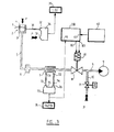
- FIG. 3 shows a variant where the output signal from the sensor 77, representative of the measured flow rate is applied to an input 46 of an electronic circuit. 200 similar in principle to circuit 100, the rest of the system being unchanged. It then becomes possible to make the measurements under the flow conditions set by the setpoint signal generator 40.
- the apparatus of the invention can be applied to the measurement of the flow-pressure characteristics of a gas other than air, and in particular of a gas charged with particles such as smoke.
- the sample considered can be, for example, the filter of a cigarette, or a cigarette.
- the measurements can also be carried out under various conditions of depression (constant, or according to a determined law of temporal variation) or of flow rate, or even relate to the rate of combustion of a cigarette under particular conditions.
- the apparatus of the invention is very well suited to measurements of the continuous type where the sample is a very long strip which passes at a certain speed in front of the sample holder, which has been suitably transformed.
- the rapid response of the apparatus of the invention makes it possible to follow precisely the variations in the characteristics of the sample, even when the latter passes relatively quickly.
Landscapes
- Chemical & Material Sciences (AREA)
- Physics & Mathematics (AREA)
- Analytical Chemistry (AREA)
- Dispersion Chemistry (AREA)
- Health & Medical Sciences (AREA)
- Life Sciences & Earth Sciences (AREA)
- Fluid Mechanics (AREA)
- Biochemistry (AREA)
- General Health & Medical Sciences (AREA)
- General Physics & Mathematics (AREA)
- Immunology (AREA)
- Pathology (AREA)
- Manufacturing Of Cigar And Cigarette Tobacco (AREA)
- Measuring Fluid Pressure (AREA)
- Sampling And Sample Adjustment (AREA)
Applications Claiming Priority (2)
| Application Number | Priority Date | Filing Date | Title |
|---|---|---|---|
| FR8419434A FR2574932B1 (fr) | 1984-12-19 | 1984-12-19 | Appareil de mesure des caracteristiques debit-pression d'un gaz traversant un echantillon de produit a deux faces |
| FR8419434 | 1984-12-19 |
Publications (2)
| Publication Number | Publication Date |
|---|---|
| EP0187089A1 true EP0187089A1 (de) | 1986-07-09 |
| EP0187089B1 EP0187089B1 (de) | 1989-11-23 |
Family
ID=9310765
Family Applications (1)
| Application Number | Title | Priority Date | Filing Date |
|---|---|---|---|
| EP85402464A Expired EP0187089B1 (de) | 1984-12-19 | 1985-12-11 | Vorrichtung zur Messung der Flussdruckcharakteristiken eines Gases das durch eine Probe eines zweiseitigen Produktes fliesst |
Country Status (5)
| Country | Link |
|---|---|
| US (1) | US4651557A (de) |
| EP (1) | EP0187089B1 (de) |
| JP (1) | JPS61149845A (de) |
| DE (1) | DE3574410D1 (de) |
| FR (1) | FR2574932B1 (de) |
Cited By (1)
| Publication number | Priority date | Publication date | Assignee | Title |
|---|---|---|---|---|
| US7608138B2 (en) | 2003-12-12 | 2009-10-27 | Ngk Insulators, Inc. | Device for measuring filter pressure loss |
Families Citing this family (12)
| Publication number | Priority date | Publication date | Assignee | Title |
|---|---|---|---|---|
| GB9414540D0 (en) * | 1994-07-19 | 1994-09-07 | At & T Global Inf Solution | Apparatus for assessing the condition of a bank note |
| FR2773882B1 (fr) * | 1998-01-22 | 2000-03-10 | Tabacs & Allumettes Ind | Permeametre a large plage de mesure |
| AU5554199A (en) * | 1998-08-11 | 2000-03-06 | Penn State Research Foundation, The | Rapid method to experimentally measure the gas permeability of micro-perforated films |
| AUPQ726600A0 (en) | 2000-05-03 | 2000-05-25 | Structural Monitoring Systems Ltd | System and method for continuous monitoring of the structural integrity of a component or structure |
| AUPQ788000A0 (en) | 2000-05-30 | 2000-06-22 | Structural Monitoring Systems Ltd | Apparatus and method for measurement of the permeability of materials |
| AUPQ823500A0 (en) | 2000-06-19 | 2000-07-13 | Structural Monitoring Systems Ltd | Apparatus for condition monitoring the integrity of fasteners and fastened joints |
| AUPR260301A0 (en) | 2001-01-18 | 2001-02-15 | Structural Monitoring Systems Ltd | Method and apparatus for remote continuous condition monitoring of a structure |
| US7500383B2 (en) * | 2001-07-13 | 2009-03-10 | Structural Monitoring Systems, Ltd. | Method and apparatus for monitoring the integrity of components and structures |
| FR2829238B1 (fr) * | 2001-08-28 | 2003-12-05 | Tabacs & Allumettes Ind | Procede et dispositif pour la determination automatique de la permeabilite d'un objet en matiere poreuse a plusieurs niveaux de porosite alternes |
| JP2009200212A (ja) * | 2008-02-21 | 2009-09-03 | Keihin Corp | プリント基板の放熱構造 |
| US10060844B2 (en) | 2016-05-23 | 2018-08-28 | Honeywell International Inc. | Pressure response method for determining properties of species-dependent leakages in gas processing equipment |
| CN106370579A (zh) * | 2016-08-30 | 2017-02-01 | 海安华达石油仪器有限公司 | 一种气体渗透率测定仪 |
Citations (5)
| Publication number | Priority date | Publication date | Assignee | Title |
|---|---|---|---|---|
| US4198853A (en) * | 1977-11-04 | 1980-04-22 | American Filtrona Corporation | Porosity measurement |
| US4311037A (en) * | 1980-03-19 | 1982-01-19 | Scott Paper Company | Web permeability tester |
| GB2094986A (en) * | 1981-03-18 | 1982-09-22 | British American Tobacco Co | Automatic pressure/flow device |
| GB2132366A (en) * | 1982-12-27 | 1984-07-04 | Brunswick Corp | Method and device for testing the permeability of membrane filters |
| US4480463A (en) * | 1981-03-23 | 1984-11-06 | B.A.T. Cigaretten-Fabriken Gmbh | Process for determining the resistance to draw and the gas _permeability of a test piece and a device for carrying out such a process |
Family Cites Families (7)
| Publication number | Priority date | Publication date | Assignee | Title |
|---|---|---|---|---|
| US3371518A (en) * | 1965-02-12 | 1968-03-05 | Beloit Corp | Device for continuously measuring porosity |
| US3466925A (en) * | 1967-08-09 | 1969-09-16 | Cons Paper Inc | Method and apparatus for measuring porosity |
| GB1239408A (de) * | 1967-10-11 | 1971-07-14 | ||
| US4191046A (en) * | 1977-07-01 | 1980-03-04 | British-American Tobacco Company Limited | Permeability meters |
| US4471649A (en) * | 1981-02-20 | 1984-09-18 | British-American Tobacco Company Limited | Permeability monitoring of sheet materials |
| US4462248A (en) * | 1981-03-18 | 1984-07-31 | British-American Tobacco Company Limited | Automatic pressure/flow device |
| US4495796A (en) * | 1982-10-25 | 1985-01-29 | R. J. Reynolds Tobacco Company | Apparatus and method for measuring permeability of a moving web |
-
1984
- 1984-12-19 FR FR8419434A patent/FR2574932B1/fr not_active Expired
-
1985
- 1985-12-11 DE DE8585402464T patent/DE3574410D1/de not_active Expired
- 1985-12-11 US US06/807,816 patent/US4651557A/en not_active Expired - Lifetime
- 1985-12-11 EP EP85402464A patent/EP0187089B1/de not_active Expired
- 1985-12-18 JP JP60283188A patent/JPS61149845A/ja active Granted
Patent Citations (5)
| Publication number | Priority date | Publication date | Assignee | Title |
|---|---|---|---|---|
| US4198853A (en) * | 1977-11-04 | 1980-04-22 | American Filtrona Corporation | Porosity measurement |
| US4311037A (en) * | 1980-03-19 | 1982-01-19 | Scott Paper Company | Web permeability tester |
| GB2094986A (en) * | 1981-03-18 | 1982-09-22 | British American Tobacco Co | Automatic pressure/flow device |
| US4480463A (en) * | 1981-03-23 | 1984-11-06 | B.A.T. Cigaretten-Fabriken Gmbh | Process for determining the resistance to draw and the gas _permeability of a test piece and a device for carrying out such a process |
| GB2132366A (en) * | 1982-12-27 | 1984-07-04 | Brunswick Corp | Method and device for testing the permeability of membrane filters |
Cited By (1)
| Publication number | Priority date | Publication date | Assignee | Title |
|---|---|---|---|---|
| US7608138B2 (en) | 2003-12-12 | 2009-10-27 | Ngk Insulators, Inc. | Device for measuring filter pressure loss |
Also Published As
| Publication number | Publication date |
|---|---|
| JPH0545135B2 (de) | 1993-07-08 |
| JPS61149845A (ja) | 1986-07-08 |
| US4651557A (en) | 1987-03-24 |
| DE3574410D1 (en) | 1989-12-28 |
| EP0187089B1 (de) | 1989-11-23 |
| FR2574932A1 (fr) | 1986-06-20 |
| FR2574932B1 (fr) | 1987-07-10 |
Similar Documents
| Publication | Publication Date | Title |
|---|---|---|
| EP0187089B1 (de) | Vorrichtung zur Messung der Flussdruckcharakteristiken eines Gases das durch eine Probe eines zweiseitigen Produktes fliesst | |
| EP1247104B1 (de) | MULTIFUNKTIONALE SONDE FüR EIN LUFTFAHRZEUG | |
| FR2532427A1 (fr) | Procede et dispositif pour la mesure de l'encrassement d'un detecteur capacitif de point de rosee | |
| FR2504261A1 (fr) | Mesureur de niveau thermoelectrique | |
| FR2626673A1 (fr) | Procede et dispositif de mesurage de la puissance calorifique vehiculee par un courant de matiere combustible | |
| EP0103771B1 (de) | Testgasleckdetektor und Vorrichtung dazu, zum Messen und Anzeigen der Leckmenge Q | |
| EP0187562B1 (de) | Durchflussmesser mit einem temperaturempfindlichen Widerstandselement | |
| FR2549164A1 (fr) | Systeme transducteur electropneumatique | |
| FR2656421A1 (fr) | Machine a fumer. | |
| FR2587485A1 (fr) | Capteur de pression | |
| EP0237390A1 (de) | Verfahren zum Regeln des Durchflusses einer Flüssigkeit durch ein Ventil und Gerät zum Durchführen dieses Verfahrens | |
| EP0932036B1 (de) | Permeameter mit grossem Messbereich | |
| EP0642456B1 (de) | Vorrichtung zur erzeugung einer inerten atmosphäre innerhalb eines lagertanks | |
| FR2678367A1 (fr) | Dispositif de mesure dimensionnelle par voie pneumatique. | |
| FR2493512A1 (fr) | Dispositif pour mesurer la planeite et la linearite de surfaces, en particulier de grandes surfaces | |
| EP0461057A1 (de) | Verfahren und Vorrichtung zur Durchflussmessung für die Regelung eines thermischen Regelungfluids in einer Leitung | |
| EP0162990A1 (de) | Einwegmesskopf und Fernmessgerät mit einem solchen Kopf | |
| FR2512860A1 (fr) | Dispositif de commande de surface de type numerique pour essais de sols et de roches in situ avec sonde profonde | |
| FR2661745A1 (fr) | Procede et dispositif de mesure de pressions instationnaires. | |
| FR2703460A1 (fr) | Dispositif de mesure directe de l'opacité des gaz. | |
| EP3066484B1 (de) | Kalibrierung einer vorrichtung zur messung eines elektrischen felds in einem leitenden medium | |
| WO1991019204A1 (fr) | Procede de mesure de caracteristiques d'une bande et dispositif de mise en ×uvre du procede | |
| FR2493511A1 (fr) | Dispositif pour la mesure de la linearite et de la planeite, notamment de grandes surfaces | |
| FR2696236A1 (fr) | Procédé et dispositif pour la localisation des truffes par la détection des composés volatils émis par ces dernières. | |
| CH390562A (fr) | Dispositif de traitement de signaux |
Legal Events
| Date | Code | Title | Description |
|---|---|---|---|
| PUAI | Public reference made under article 153(3) epc to a published international application that has entered the european phase |
Free format text: ORIGINAL CODE: 0009012 |
|
| AK | Designated contracting states |
Kind code of ref document: A1 Designated state(s): DE FR GB |
|
| 17P | Request for examination filed |
Effective date: 19861006 |
|
| 17Q | First examination report despatched |
Effective date: 19880229 |
|
| GRAA | (expected) grant |
Free format text: ORIGINAL CODE: 0009210 |
|
| AK | Designated contracting states |
Kind code of ref document: B1 Designated state(s): DE FR GB |
|
| REF | Corresponds to: |
Ref document number: 3574410 Country of ref document: DE Date of ref document: 19891228 |
|
| GBT | Gb: translation of ep patent filed (gb section 77(6)(a)/1977) | ||
| PLBE | No opposition filed within time limit |
Free format text: ORIGINAL CODE: 0009261 |
|
| STAA | Information on the status of an ep patent application or granted ep patent |
Free format text: STATUS: NO OPPOSITION FILED WITHIN TIME LIMIT |
|
| 26N | No opposition filed | ||
| REG | Reference to a national code |
Ref country code: GB Ref legal event code: IF02 |
|
| PGFP | Annual fee paid to national office [announced via postgrant information from national office to epo] |
Ref country code: FR Payment date: 20040914 Year of fee payment: 20 |
|
| PGFP | Annual fee paid to national office [announced via postgrant information from national office to epo] |
Ref country code: GB Payment date: 20041124 Year of fee payment: 20 |
|
| PGFP | Annual fee paid to national office [announced via postgrant information from national office to epo] |
Ref country code: DE Payment date: 20041221 Year of fee payment: 20 |
|
| PG25 | Lapsed in a contracting state [announced via postgrant information from national office to epo] |
Ref country code: GB Free format text: LAPSE BECAUSE OF EXPIRATION OF PROTECTION Effective date: 20051210 |
|
| REG | Reference to a national code |
Ref country code: GB Ref legal event code: PE20 |