EP0187097A2 - Vorrichtung für Probenahme im Bohrloch - Google Patents
Vorrichtung für Probenahme im Bohrloch Download PDFInfo
- Publication number
- EP0187097A2 EP0187097A2 EP85402544A EP85402544A EP0187097A2 EP 0187097 A2 EP0187097 A2 EP 0187097A2 EP 85402544 A EP85402544 A EP 85402544A EP 85402544 A EP85402544 A EP 85402544A EP 0187097 A2 EP0187097 A2 EP 0187097A2
- Authority
- EP
- European Patent Office
- Prior art keywords
- valve
- ball
- pressure
- housing
- operator
- Prior art date
- Legal status (The legal status is an assumption and is not a legal conclusion. Google has not performed a legal analysis and makes no representation as to the accuracy of the status listed.)
- Granted
Links
Images


Classifications
-
- E—FIXED CONSTRUCTIONS
- E21—EARTH OR ROCK DRILLING; MINING
- E21B—EARTH OR ROCK DRILLING; OBTAINING OIL, GAS, WATER, SOLUBLE OR MELTABLE MATERIALS OR A SLURRY OF MINERALS FROM WELLS
- E21B49/00—Testing the nature of borehole walls; Formation testing; Methods or apparatus for obtaining samples of soil or well fluids, specially adapted to earth drilling or wells
- E21B49/08—Obtaining fluid samples or testing fluids, in boreholes or wells
- E21B49/087—Well testing, e.g. testing for reservoir productivity or formation parameters
- E21B49/088—Well testing, e.g. testing for reservoir productivity or formation parameters combined with sampling
-
- E—FIXED CONSTRUCTIONS
- E21—EARTH OR ROCK DRILLING; MINING
- E21B—EARTH OR ROCK DRILLING; OBTAINING OIL, GAS, WATER, SOLUBLE OR MELTABLE MATERIALS OR A SLURRY OF MINERALS FROM WELLS
- E21B34/00—Valve arrangements for boreholes or wells
- E21B34/06—Valve arrangements for boreholes or wells in wells
- E21B34/10—Valve arrangements for boreholes or wells in wells operated by control fluid supplied from outside the borehole
-
- E—FIXED CONSTRUCTIONS
- E21—EARTH OR ROCK DRILLING; MINING
- E21B—EARTH OR ROCK DRILLING; OBTAINING OIL, GAS, WATER, SOLUBLE OR MELTABLE MATERIALS OR A SLURRY OF MINERALS FROM WELLS
- E21B2200/00—Special features related to earth drilling for obtaining oil, gas or water
- E21B2200/04—Ball valves
Definitions
- This invention relates generally to apparatus for obtaining a sample of fluid from a producing formation, generally called a bottom hole sampler, and in particular to a sampler of the type that is generally used in combination with drill stem testing tools.
- this invention relates to a downhole safety valve.
- the invention relates to a valve for use in such tools.
- Drill stem tests are conducted primarily to determine whether a fluid bearing formation penetrated by the well bore will produce oil or gas in sufficient quantities to justify completing the well in that formation.
- the formation is relieved of the hydrostatic pressure of the arilling fluid in the well bore sufficiently to allow the fluids in the formation to flow into the well bore ana up the drill pipe under substantially the same conditions that would exist after the well is completed. Measurements are made of the pressure in the well bore adjacent the formation, while the formation is flowing and while it is shut in. It is also helpful in the evaluation of the formation to obtain a sample of the produced fluid at the pressure and temperature of the producing formation. This is the function of the bottom hole sampler to which this invention relates.
- bottom hole samplers include a tubular member that is connected into the drill string and forms part of the passageway through which the formation fluid travels as it moves up the drill pipe.
- the sampler is usually located in the drill string as close to the producing formation as practical.
- valves located at opposite ends of the tubular member are closed trapping the formation fluid in the sampler at or about the temperature and pressure of the fluid in the formation.
- Ball valve type samplers in the past have been prone to malfunction due to solids, such as cuttings, wall cake, barites or the like, collecting in the somewhat complicated parts used to operate the ball valves. In many cases, if one of the ball valves will not close for any reason, the other will not either, since they are both closed by the same mechanism. This is not a critical situation as far as the sampler is concerned' since if one doesn't close, the sampler cannot function properly anyway, but it is important when the sampler is acting as a safety valve.
- a bottom hole sampler for obtaining a sample of the fluids produced by a subsurface formation during a drill stem test at formation pressure and temperature
- a tubular housing having a passageway through which fluids produced can flow during said test, a pair of ball valves spaced along the passageway to trap fluid in the passageway when the valves are closea, each valve including a ball having an opening therethrough, a valve seat engaging the ball, means mounting the ball for rotation around an axis transverse the longitudinal axis of the passageway, a valve operator connected to the ball to rotate the ball to an open position with its opening parallel to the longitudinal axis of the passageway when the operator is moved in one direction and to rotate the ball to a closed position with the opening extending transverse the longitudinal axis of the passageway when the operator is moved in the opposite direction, piston means connected to the valve operator responsive to fluid pressure to move the valve operator in said opposite direction to close the valve, and reset means operable through the open end
- a ball valve for use in downhole tools such as bottom hole samplers and safety valves comprising a tubular housing, a ball having an opening therethrough, a valve seat engaging the ball, means mounting the ball'for rotation around an axis transverse the longitudinal axis of the housing, a valve operator connected to the ball to rotate the ball to an open position with its opening parallel to the longitudinal axis of the housing when the operator is moved in one direction ana to rotate the ball to a closed position with the opening extending transverse the longitudinal axis of the housing when the operator is moved in the opposite direction, piston means connected to the valve operator responsive to fluid pressure to move the valve operator in one direction, and reset means operable through the open end of the housing for moving the valve operator to return the valve to the open position.
- a further aspect of the invention comprises a ball valve assembly for use in a downhole tool, such as a bottom hole sampler or safety valve, to close the bore of the housing of the tool comprising a ball having a central bore therethrough, a pair of trunnions attached to the ball on opposite sides, first and second cage members on opposite sides of the ball along the longitudinal axis of the tool in engagement with the trunnions to support the trunnions and ball for rotation thereon trunnions between an open position with the bore in the ball extending in the direction of the bore of the tool and a closed position with the bore of the ball extending transverse the bore of the tool, resilient means urging the valve seat, a valve operator assembly including an annular cylindrical section along the bore of the tool, an annular piston located in the cylindrical section of the bore, an annular skirt attached to the piston and extending away from the piston on the opposite side from the ball to confine fluid under pressure in between the cylindrical section and the skirt to urge the piston to move toward the ball, a valve operator attached to the
- a well tool adapted to be connected in a pipe string and positioned in a well bore for collecting fluids within said pipe string and comprising a tubular housing having an axial passage with an intermediate portion thereof defining a sample chamber; first and second valve means within said passage at opposite ends of said sample chamber controlling communication therewith and respectively including a ball member rotatable between open and closed positions, an annular valve seat slidably mounted in said sample chamber and adapted for axial movement toward the adjacent side of said ball member, and spring means normally biasing said valve seat toward said ball member; first and second pressure-biasing means arranged between said housing and said valve seats for urging said valve seats against said adjacent sides of said ball members and respectively including an annular follower sealingly mounted between said housing and said valve seat and adapted for axial movement relative thereto, said follower and said valve seat cooperatively combining to provide a first area on said follower responsive to the pressure in said sample chamber for urging said follower against said valve seat and thereby maintain said valve seat engaged with said ball member whenever said
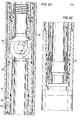
- the bottom hole assembly shown in Figure 1 is a typical one for conducting a drill stem test in a cased hole.
- casing string 10 has been run into the well bore and cemented in the conventional manner to isolate the various producing formations, only one of which, F, is shown in Figure 1.
- the assembly is supported by drill pipe 11 that extends to the surface and provides a conduit through which the fluids produced by the formation flow to the surface.
- Packer 12 isolates formation F from the hydrostatic pressure of the drilling fluid in annulus 22 between the drill pipe and the casing above the packer and allows the pressure below the packer to be reduced to induce the fluids in the formation to flow into the casing below the packer and up through the drill pipe to the surface.
- Test valve assembly 13 is closed as the bottom hole assembly is run into the well bore.
- a water blanket is in the drill pipe above the test valve so that the pressure differential across the test valve does not become excessive.
- Below packer 12 is a perforated section of pipe 14 through which the well fluid can flow into the drill string.
- Pressure gauges are located in sections 15 below the perforated pipe to measure and record the flowing and shut-in pressure of the fluids in the formation.
- One or more bottom hole samplers can be included in the bottom hole assembly. In Figure 1, two samplers 20 and 21 are connected between the drill pipe and the test valve.
- top sub 25 includes tool joint box 26 for connecting the sampler to the drill pipe.
- the lower end of the top sub is connectea to upper valve housing 27 by threaded connection 28.
- the lower end of upper valve housing 27 ( Figure 2B) is connected to drain sub 30 ( Figure 2C).
- Below drain sub 30 are lower valve housing 32 ( Figure 2D) and bottom sub 33 ( Figure 2E).
- the bottom sub is equipped with a drill pipe pin connection for connecting to the box of the next lower component of the string.
- valve elements 34 and 35 Located in the upper and lower valve housings 27 and 32 are new and improved ball valves arranged in accordance with the principles of the present invention which respectively employ ball shaped valve elements 34 and 35. These elements are identical as are the upper and lower valve operator mechanisms for opening and closing the valves and the valve seats that engage the ball members. The only difference is that the ball valves are arranged within the outer housing in opposition to one another to dispose the valve operators in the passageway outside of the sample chamber between the upper and lower ball valves. Therefore, only the ball valve in the upper housing 27 will be described in detail.
- the ball member 34 has central opening 36 that is moved into alignment with the longitudinal axis of the sampler when the valve is opened and is moved to a position transverse the longitudinal axis when the valve is closed.
- the valve is shown in the closed position in Figure 2B. It is mounted for rotation in upper valve housing 27 by upper valve cage 38 and lower valve cage 39.
- Both valve cages are tubular members having parallel arms extending toward the ball.
- Upper cage 38 has parallel arms 41 and 42 extending from the tubular portion of the cage. Each arm is slotted to receive trunnions 44 located on opposite sides of ball 34.
- Arms 45 and 46 on lower cage 39 extend into slots 43 of arms 41 and 42 and engage the other side of the trunnions 44 so that the ball member 34 is operatively journalled on the cage arms for rotation about the transverse pivotal axis defined by the trunnions.
- the cages hold the ball from longitudinal movement relative to the cages and in turn the cages are held against longitudinal movement relative to upper valve housing 27 by shoulder 48 on the upper valve housing and the upper end 49 of drain sub 30.
- Valve operator means are provided to engage the ball and rotate the ball between its open and closed positions upon longitudinal movement of the valve operator means.
- the valve operator 50 includes tubular section 50a that is supported for longitudinal movement along its longitudinal axis by bore 51 of upper cage member 38.
- the tubular member 50a is shaped to define an elongated arm 50b along one side thereof which supports outwardly-projecting pins or stub shafts 52 and 53 which are slidably engaged within complemental inclined slots 54 and 55 on opposite sides of ball 34.
- Bushings 56 can be mounted on the stub shafts to reduce the friction between the stub shafts and the surface of the grooves as the operator moves the ball between the open and closed positions as shown in Figures 4A and 4B.
- window 58 is millea out of the ball leaving siaewalls 59 and 60 that are spaced enough to allow arm 51a to move between them as it moves the valve to the closed position.
- Slots 54 and 55 are cut in sidewalls 59 and 60.
- the upper ball valve further includes piston means comprised of a tubular operator mandrel 62 that is slidably arranged within bore 51 of the upper valve cage 38 and connected to valve operator 50 by threads 63.
- An intermediate portion of the operator mandrel 62 is enlarged in diameter to provide a piston 64 which is complementally fitted within an enlarged-diameter annular space 66 arranged in the upper portion of upper valve cage 38.
- O-rings 67 and 68 are cooperatively arranged between operator mandrel 62 and valve cage 38 to confine a pressured operating fluid within annular chamber 66 when the mandrel is to be moved downwardly to close the upper ball valve.
- a third 0-ring 69 is cooperatively arranged between the lower portions of valve cage 38 and mandrel 62 to provide an annular chamber at atmospheric pressure below piston 64 into which the piston moves upon downward travel of the operator mandrel.
- Drain sub 30 is equipped with longitudinally extending fluid passages 70 and 71 in the housing walls on opposite sides of the sub that extend th p length of the drain sub.
- longitudinal passage 70 is communicated by means of facing lateral ports 73 and 74 and an annular groove 75 to a similar longitudinal passage 72 in the housing.
- Annular groove 75 also allows fluid pressure in passage 70 to be communicated by way of opposed ports 77 and 78 to a longitudinal passage 76 in housing 27.
- the fluid pressure in longitudinal passages 72 and 76 is transmitted to annular space 66 through lateral ports 79 and 80.
- longitudinal passage 70 in the drain sub is communicated with the well annulus 22 through port 82 that is closed by plug 83.
- the plug has central opening 84 that is closed by rupture disc 86 held in place by set screw 87.
- the pressure in the annulus is built up sufficiently to rupture disc 86. This allows the pressure in the annulus to be transmitted to annular chamber 66 at the upper end of the sampler and to chamber 89 at the lower end of the sampler.
- the fluid pressures moves valve operator 64 downwardly thereby rotating ball 34 to the closed position as shown in Figure 2B.
- piston 90 on operator mandrel 91 moves valve operator 92 upwardly rotating ball 35 to the closed position.
- reset means are operatively arranged to enable the valve operators to be moved freely in one axial direction for closing ball valves 34 and 35 whenever pressure is admitted to piston chambers 66 and 89; but the reset means will thereafter positively restrain the valve operators against subsequently moving in the opposite axial direction and thereby inadvertently re-opening the ball valves while the sampler is still in the well bore.
- the new and improved reset means are further arranged to manually re-open ball valves 34 and 35 while the sampler is at the surface. In this manner, the sampler can be readily tested in advance without having to disassemble the sampler.
- the reset means includes collet 100 which is equipped with a plurality of spaced parallel fingers 102. Threads 103 on the fingers mate with threads 104 on the upper end of operator mandrel 62.
- the outer end of each finger two of which can be seen in Figure 2A, have ridges 105 with tapered sides that can move upwardly into mating cavity 106 when the fingers are bent outwardly by the force imposed on the fingers by threads 104 on the operator mandrel as fluid pressure acts on piston 64 urging the operator mandrel downwardly, as viewed in Figure 2A, when the valve is being closed.
- the fingers will be successively expanded and contracted as they ratchet along threads 104 as the operator mandrel moves downwardly.
- the collet is held against longitudinal movement relative to the operator mandrel by shoulder 108 that engages the end of upper housing 27. Any tendency of the operator mandrel to move upwardly will cause the tapered sides of ridges 104 to engage the corresponding tapered side of groove 106 and prevent the fingers from moving out of engagement with the threads thereby holding the operator mandrel from such movement.
- collet 100 serves as a nut with the threads 103 and 104 coacting to raise operator mandrel 64 upwardly, as viewed in Figure 2A, and return ball 34 to the open position. The same can be done at the other end by rotating collet 112.
- the new and improved ball valve 34 includes resilient or spring means such as valve seat spring 116 which is cooperatively arranged within housing 27 for urging valve seal retainer 118 toward ball 34 to hold seal 120 in sealing engagement with the spherical surface of the ball.
- inside pressure P 2 is also uniquely employed for biasing the seal retainer 118 and seal 120 against the valve member 34 whenever the pressure in the sample chamber is greater than the outside pressure.
- an annular seal follower 122 is cooperatively arranged between the valve cage 39 and seal retainer 118 and sealingly engaged therewith by inner and outer O-rings 122a and 122b mounted on the seal follower.
- the sample chamber pressure does, however, act against the annular surface (A4 - A 3 ) on seal follower 122.
- T nus, whenever the pressure P 2 in the sample chamber is greater than the exterior pressure P 1 , the resulting pressure differential biases the seal follower 122 against the seal retainer 118 which urges the seal 120 toward ball member 34.
- seal follower 122 is moved away from seal retainer 118 and stopped against the nearby housing shoulder 49.
- the sampler of this invention employs ball valves of simplified design that are closed by hydraulic pressure independently of each other so that if it should for some reason one should fail to close the other valve can. Since the sampler also acts as a safety valve, the fact that one will operate when the other one doesn't is an extremely important feature.
Landscapes
- Life Sciences & Earth Sciences (AREA)
- Engineering & Computer Science (AREA)
- Geology (AREA)
- Mining & Mineral Resources (AREA)
- Physics & Mathematics (AREA)
- Environmental & Geological Engineering (AREA)
- Fluid Mechanics (AREA)
- General Life Sciences & Earth Sciences (AREA)
- Geochemistry & Mineralogy (AREA)
- Sampling And Sample Adjustment (AREA)
Applications Claiming Priority (2)
| Application Number | Priority Date | Filing Date | Title |
|---|---|---|---|
| US06/686,576 US4610308A (en) | 1984-12-27 | 1984-12-27 | Bottom hole sampler and safety valve and valve therefor |
| US686576 | 1984-12-27 |
Publications (3)
| Publication Number | Publication Date |
|---|---|
| EP0187097A2 true EP0187097A2 (de) | 1986-07-09 |
| EP0187097A3 EP0187097A3 (en) | 1988-09-21 |
| EP0187097B1 EP0187097B1 (de) | 1993-12-15 |
Family
ID=24756884
Family Applications (1)
| Application Number | Title | Priority Date | Filing Date |
|---|---|---|---|
| EP85402544A Expired - Lifetime EP0187097B1 (de) | 1984-12-27 | 1985-12-18 | Vorrichtung für Probenahme im Bohrloch |
Country Status (6)
| Country | Link |
|---|---|
| US (1) | US4610308A (de) |
| EP (1) | EP0187097B1 (de) |
| BR (1) | BR8506548A (de) |
| CA (1) | CA1236002A (de) |
| MX (1) | MX166729B (de) |
| NO (1) | NO170503C (de) |
Cited By (2)
| Publication number | Priority date | Publication date | Assignee | Title |
|---|---|---|---|---|
| EP0204619A3 (en) * | 1985-05-31 | 1988-06-01 | Schlumberger Technology Corporation | Subsea master valve for use in well testing |
| GB2222623A (en) * | 1988-09-07 | 1990-03-14 | Atlantic Richfield Co | Wellbore fluid sampling apparatus. |
Families Citing this family (12)
| Publication number | Priority date | Publication date | Assignee | Title |
|---|---|---|---|---|
| US4979569A (en) * | 1989-07-06 | 1990-12-25 | Schlumberger Technology Corporation | Dual action valve including at least two pressure responsive members |
| US5220962A (en) * | 1991-09-24 | 1993-06-22 | Schlumberger Technology Corporation | Pump apparatus for pumping well fluids from a wellbore having low formation pressure |
| US5320183A (en) * | 1992-10-16 | 1994-06-14 | Schlumberger Technology Corporation | Locking apparatus for locking a packer setting apparatus and preventing the packer from setting until a predetermined annulus pressure is produced |
| US5361839A (en) * | 1993-03-24 | 1994-11-08 | Schlumberger Technology Corporation | Full bore sampler including inlet and outlet ports flanking an annular sample chamber and parameter sensor and memory apparatus disposed in said sample chamber |
| US5411097A (en) * | 1994-05-13 | 1995-05-02 | Halliburton Company | High pressure conversion for circulating/safety valve |
| GB9413142D0 (en) * | 1994-06-30 | 1994-08-24 | Exploration And Production Nor | Completion lubricator valve |
| US5819853A (en) * | 1995-08-08 | 1998-10-13 | Schlumberger Technology Corporation | Rupture disc operated valves for use in drill stem testing |
| CA2412072C (en) | 2001-11-19 | 2012-06-19 | Packers Plus Energy Services Inc. | Method and apparatus for wellbore fluid treatment |
| US8167047B2 (en) | 2002-08-21 | 2012-05-01 | Packers Plus Energy Services Inc. | Method and apparatus for wellbore fluid treatment |
| GB0721353D0 (en) * | 2007-10-31 | 2007-12-12 | Expro North Sea Ltd | Connecting assembly |
| US8757273B2 (en) | 2008-04-29 | 2014-06-24 | Packers Plus Energy Services Inc. | Downhole sub with hydraulically actuable sleeve valve |
| MX2019002520A (es) * | 2016-09-21 | 2019-07-04 | Halliburton Energy Services Inc | Valvula de esfera con esfera soluble. |
Family Cites Families (11)
| Publication number | Priority date | Publication date | Assignee | Title |
|---|---|---|---|---|
| US2442642A (en) * | 1946-06-27 | 1948-06-01 | John E Eckel | Double-acting valve assembly |
| US3543793A (en) * | 1965-01-29 | 1970-12-01 | Otis Eng Corp | Well tools |
| US3856085A (en) * | 1973-11-15 | 1974-12-24 | Halliburton Co | Improved annulus pressure operated well testing apparatus and its method of operation |
| US3901321A (en) * | 1973-12-26 | 1975-08-26 | Hydril Co | Safety valve method and apparatus |
| US3993136A (en) * | 1975-08-25 | 1976-11-23 | Hydril Company | Apparatus for operating a closure element of a subsurface safety valve and method of using same |
| US4063593A (en) * | 1977-02-16 | 1977-12-20 | Halliburton Company | Full-opening annulus pressure operated sampler valve with reverse circulation valve |
| US4270610A (en) * | 1980-01-15 | 1981-06-02 | Halliburton Company | Annulus pressure operated closure valve with improved power mandrel |
| US4474242A (en) * | 1981-06-29 | 1984-10-02 | Schlumberger Technology Corporation | Annulus pressure controlled reversing valve |
| US4553598A (en) * | 1981-08-06 | 1985-11-19 | Schlumberger Technology Corporation | Full bore sampler valve apparatus |
| US4446922A (en) * | 1982-06-16 | 1984-05-08 | Baker Oil Tools, Inc. | Adjustable safety valve |
| US4576234A (en) * | 1982-09-17 | 1986-03-18 | Schlumberger Technology Corporation | Full bore sampler valve |
-
1984
- 1984-12-27 US US06/686,576 patent/US4610308A/en not_active Expired - Lifetime
-
1985
- 1985-12-05 NO NO854901A patent/NO170503C/no unknown
- 1985-12-18 EP EP85402544A patent/EP0187097B1/de not_active Expired - Lifetime
- 1985-12-24 CA CA000498590A patent/CA1236002A/en not_active Expired
- 1985-12-27 MX MX001104A patent/MX166729B/es unknown
- 1985-12-27 BR BR8506548A patent/BR8506548A/pt not_active IP Right Cessation
Cited By (2)
| Publication number | Priority date | Publication date | Assignee | Title |
|---|---|---|---|---|
| EP0204619A3 (en) * | 1985-05-31 | 1988-06-01 | Schlumberger Technology Corporation | Subsea master valve for use in well testing |
| GB2222623A (en) * | 1988-09-07 | 1990-03-14 | Atlantic Richfield Co | Wellbore fluid sampling apparatus. |
Also Published As
| Publication number | Publication date |
|---|---|
| EP0187097B1 (de) | 1993-12-15 |
| MX166729B (es) | 1993-02-01 |
| NO170503B (no) | 1992-07-13 |
| BR8506548A (pt) | 1986-09-09 |
| NO170503C (no) | 1992-10-21 |
| US4610308A (en) | 1986-09-09 |
| CA1236002A (en) | 1988-05-03 |
| EP0187097A3 (en) | 1988-09-21 |
| NO854901L (no) | 1986-06-30 |
Similar Documents
| Publication | Publication Date | Title |
|---|---|---|
| US4610308A (en) | Bottom hole sampler and safety valve and valve therefor | |
| US4678035A (en) | Methods and apparatus for subsurface testing of well bore fluids | |
| CA2006894C (en) | Delayed opening fluid sampler | |
| US4597439A (en) | Full-bore sample-collecting apparatus | |
| US4576234A (en) | Full bore sampler valve | |
| US5337827A (en) | Pressure-controlled well tester adapted to be selectively retained in a predetermined operating position | |
| US4979569A (en) | Dual action valve including at least two pressure responsive members | |
| US4278130A (en) | Access valve for drill stem testing | |
| AU759354B2 (en) | Eccentric subsurface safety valve | |
| US4553598A (en) | Full bore sampler valve apparatus | |
| US4736798A (en) | Rapid cycle annulus pressure responsive tester valve | |
| US4252195A (en) | Well test systems and methods | |
| NO340242B1 (no) | Brønnverktøysystem samt fremgangsmåte for å operere et nedihulls brønnverktøy | |
| GB1598863A (en) | Well tubing tester valve apparatus | |
| US4399870A (en) | Annulus operated test valve | |
| US4915171A (en) | Above packer perforate test and sample tool and method of use | |
| US4624317A (en) | Well tool with improved valve support structure | |
| US4582140A (en) | Well tool with selective bypass functions | |
| US4579174A (en) | Well tool with hydraulic time delay | |
| CA1129338A (en) | Well safety system | |
| US5337826A (en) | Tester valve | |
| EP0023112A1 (de) | Ventil, insbesondere für einen Förderrohrstrang | |
| EP0024214B1 (de) | Umleitungsventil für einen Apparat zum Untersuchen eines Bohrloches | |
| US2751011A (en) | Side wall testing apparatus | |
| GB2132250A (en) | Full bore sampler valve apparatus |
Legal Events
| Date | Code | Title | Description |
|---|---|---|---|
| PUAI | Public reference made under article 153(3) epc to a published international application that has entered the european phase |
Free format text: ORIGINAL CODE: 0009012 |
|
| AK | Designated contracting states |
Kind code of ref document: A2 Designated state(s): FR GB NL |
|
| PUAL | Search report despatched |
Free format text: ORIGINAL CODE: 0009013 |
|
| AK | Designated contracting states |
Kind code of ref document: A3 Designated state(s): FR GB NL |
|
| 17P | Request for examination filed |
Effective date: 19890222 |
|
| 17Q | First examination report despatched |
Effective date: 19900517 |
|
| GRAA | (expected) grant |
Free format text: ORIGINAL CODE: 0009210 |
|
| AK | Designated contracting states |
Kind code of ref document: B1 Designated state(s): FR GB NL |
|
| PG25 | Lapsed in a contracting state [announced via postgrant information from national office to epo] |
Ref country code: NL Effective date: 19931215 |
|
| ET | Fr: translation filed | ||
| NLV1 | Nl: lapsed or annulled due to failure to fulfill the requirements of art. 29p and 29m of the patents act | ||
| PLBE | No opposition filed within time limit |
Free format text: ORIGINAL CODE: 0009261 |
|
| STAA | Information on the status of an ep patent application or granted ep patent |
Free format text: STATUS: NO OPPOSITION FILED WITHIN TIME LIMIT |
|
| 26N | No opposition filed | ||
| PGFP | Annual fee paid to national office [announced via postgrant information from national office to epo] |
Ref country code: FR Payment date: 19990915 Year of fee payment: 15 |
|
| PG25 | Lapsed in a contracting state [announced via postgrant information from national office to epo] |
Ref country code: FR Free format text: LAPSE BECAUSE OF NON-PAYMENT OF DUE FEES Effective date: 20010831 |
|
| REG | Reference to a national code |
Ref country code: FR Ref legal event code: ST |
|
| REG | Reference to a national code |
Ref country code: GB Ref legal event code: IF02 |
|
| PGFP | Annual fee paid to national office [announced via postgrant information from national office to epo] |
Ref country code: GB Payment date: 20041215 Year of fee payment: 20 |
|
| PG25 | Lapsed in a contracting state [announced via postgrant information from national office to epo] |
Ref country code: GB Free format text: LAPSE BECAUSE OF EXPIRATION OF PROTECTION Effective date: 20051217 |
|
| REG | Reference to a national code |
Ref country code: GB Ref legal event code: PE20 |