EP0187100B1 - Einheit von Konstruktionselementen zum Bau von Räumlichkeiten für Ausstellungen, zum Wohnen oder geeignet für andere Verwendungszwecke - Google Patents
Einheit von Konstruktionselementen zum Bau von Räumlichkeiten für Ausstellungen, zum Wohnen oder geeignet für andere Verwendungszwecke Download PDFInfo
- Publication number
- EP0187100B1 EP0187100B1 EP85402557A EP85402557A EP0187100B1 EP 0187100 B1 EP0187100 B1 EP 0187100B1 EP 85402557 A EP85402557 A EP 85402557A EP 85402557 A EP85402557 A EP 85402557A EP 0187100 B1 EP0187100 B1 EP 0187100B1
- Authority
- EP
- European Patent Office
- Prior art keywords
- structural member
- elements
- assembly
- attachment
- accordance
- Prior art date
- Legal status (The legal status is an assumption and is not a legal conclusion. Google has not performed a legal analysis and makes no representation as to the accuracy of the status listed.)
- Expired
Links
Images



Classifications
-
- E—FIXED CONSTRUCTIONS
- E04—BUILDING
- E04B—GENERAL BUILDING CONSTRUCTIONS; WALLS, e.g. PARTITIONS; ROOFS; FLOORS; CEILINGS; INSULATION OR OTHER PROTECTION OF BUILDINGS
- E04B1/00—Constructions in general; Structures which are not restricted either to walls, e.g. partitions, or floors or ceilings or roofs
- E04B1/18—Structures comprising elongated load-supporting parts, e.g. columns, girders, skeletons
- E04B1/19—Three-dimensional [3D] framework structures
-
- E—FIXED CONSTRUCTIONS
- E04—BUILDING
- E04B—GENERAL BUILDING CONSTRUCTIONS; WALLS, e.g. PARTITIONS; ROOFS; FLOORS; CEILINGS; INSULATION OR OTHER PROTECTION OF BUILDINGS
- E04B1/00—Constructions in general; Structures which are not restricted either to walls, e.g. partitions, or floors or ceilings or roofs
- E04B1/18—Structures comprising elongated load-supporting parts, e.g. columns, girders, skeletons
- E04B1/19—Three-dimensional [3D] framework structures
- E04B1/1903—Connecting nodes specially adapted therefor
-
- F—MECHANICAL ENGINEERING; LIGHTING; HEATING; WEAPONS; BLASTING
- F16—ENGINEERING ELEMENTS AND UNITS; GENERAL MEASURES FOR PRODUCING AND MAINTAINING EFFECTIVE FUNCTIONING OF MACHINES OR INSTALLATIONS; THERMAL INSULATION IN GENERAL
- F16B—DEVICES FOR FASTENING OR SECURING CONSTRUCTIONAL ELEMENTS OR MACHINE PARTS TOGETHER, e.g. NAILS, BOLTS, CIRCLIPS, CLAMPS, CLIPS OR WEDGES; JOINTS OR JOINTING
- F16B7/00—Connections of rods or tubes, e.g. of non-circular section, mutually, including resilient connections
- F16B7/04—Clamping or clipping connections
- F16B7/044—Clamping or clipping connections for rods or tubes being in angled relationship
- F16B7/0446—Clamping or clipping connections for rods or tubes being in angled relationship for tubes using the innerside thereof
- F16B7/0473—Clamping or clipping connections for rods or tubes being in angled relationship for tubes using the innerside thereof with hook-like parts gripping, e.g. by expanding, behind the flanges of a profile
-
- E—FIXED CONSTRUCTIONS
- E04—BUILDING
- E04B—GENERAL BUILDING CONSTRUCTIONS; WALLS, e.g. PARTITIONS; ROOFS; FLOORS; CEILINGS; INSULATION OR OTHER PROTECTION OF BUILDINGS
- E04B1/00—Constructions in general; Structures which are not restricted either to walls, e.g. partitions, or floors or ceilings or roofs
- E04B1/18—Structures comprising elongated load-supporting parts, e.g. columns, girders, skeletons
- E04B1/19—Three-dimensional [3D] framework structures
- E04B1/1903—Connecting nodes specially adapted therefor
- E04B1/1912—Connecting nodes specially adapted therefor with central cubical connecting element
-
- E—FIXED CONSTRUCTIONS
- E04—BUILDING
- E04B—GENERAL BUILDING CONSTRUCTIONS; WALLS, e.g. PARTITIONS; ROOFS; FLOORS; CEILINGS; INSULATION OR OTHER PROTECTION OF BUILDINGS
- E04B1/00—Constructions in general; Structures which are not restricted either to walls, e.g. partitions, or floors or ceilings or roofs
- E04B1/18—Structures comprising elongated load-supporting parts, e.g. columns, girders, skeletons
- E04B1/19—Three-dimensional [3D] framework structures
- E04B2001/1924—Struts specially adapted therefor
-
- E—FIXED CONSTRUCTIONS
- E04—BUILDING
- E04B—GENERAL BUILDING CONSTRUCTIONS; WALLS, e.g. PARTITIONS; ROOFS; FLOORS; CEILINGS; INSULATION OR OTHER PROTECTION OF BUILDINGS
- E04B1/00—Constructions in general; Structures which are not restricted either to walls, e.g. partitions, or floors or ceilings or roofs
- E04B1/18—Structures comprising elongated load-supporting parts, e.g. columns, girders, skeletons
- E04B1/19—Three-dimensional [3D] framework structures
- E04B2001/1924—Struts specially adapted therefor
- E04B2001/1927—Struts specially adapted therefor of essentially circular cross section
-
- E—FIXED CONSTRUCTIONS
- E04—BUILDING
- E04B—GENERAL BUILDING CONSTRUCTIONS; WALLS, e.g. PARTITIONS; ROOFS; FLOORS; CEILINGS; INSULATION OR OTHER PROTECTION OF BUILDINGS
- E04B1/00—Constructions in general; Structures which are not restricted either to walls, e.g. partitions, or floors or ceilings or roofs
- E04B1/18—Structures comprising elongated load-supporting parts, e.g. columns, girders, skeletons
- E04B1/19—Three-dimensional [3D] framework structures
- E04B2001/1957—Details of connections between nodes and struts
- E04B2001/1966—Formlocking connections other than screw connections
-
- F—MECHANICAL ENGINEERING; LIGHTING; HEATING; WEAPONS; BLASTING
- F16—ENGINEERING ELEMENTS AND UNITS; GENERAL MEASURES FOR PRODUCING AND MAINTAINING EFFECTIVE FUNCTIONING OF MACHINES OR INSTALLATIONS; THERMAL INSULATION IN GENERAL
- F16B—DEVICES FOR FASTENING OR SECURING CONSTRUCTIONAL ELEMENTS OR MACHINE PARTS TOGETHER, e.g. NAILS, BOLTS, CIRCLIPS, CLAMPS, CLIPS OR WEDGES; JOINTS OR JOINTING
- F16B2200/00—Constructional details of connections not covered for in other groups of this subclass
- F16B2200/40—Clamping arrangements where clamping parts are received in recesses of elements to be connected
-
- Y—GENERAL TAGGING OF NEW TECHNOLOGICAL DEVELOPMENTS; GENERAL TAGGING OF CROSS-SECTIONAL TECHNOLOGIES SPANNING OVER SEVERAL SECTIONS OF THE IPC; TECHNICAL SUBJECTS COVERED BY FORMER USPC CROSS-REFERENCE ART COLLECTIONS [XRACs] AND DIGESTS
- Y10—TECHNICAL SUBJECTS COVERED BY FORMER USPC
- Y10T—TECHNICAL SUBJECTS COVERED BY FORMER US CLASSIFICATION
- Y10T403/00—Joints and connections
- Y10T403/55—Member ends joined by inserted section
- Y10T403/557—Expansible section
Definitions
- the present invention relates to a set of construction elements for the production of three-dimensional structures with a view to arranging exhibition spaces, housing, offices or used for other uses.
- German application DE 1 775 597 describes a system for assembling profiled elements by means of a junction node constituted by a hollow block whose different faces have an opening.
- the fixing of each profiled element on this junction knot is ensured by the curved ends of a spring leaf disposed inside the end of each of these elements.
- a simple attachment is obtained which does not have sufficient strength and rigidity for such a system to be used for the assembly of construction elements.
- German application DE 2 633 147 it describes an assembly system in which there are also provided junction nodes each consisting of a hollow block having openings oriented in different directions.
- the end of each profile carries a fixing end piece ending in a head capable of being hooked, by rotation, inside one of the openings of a junction node.
- This fixing end piece is screwed into a nut carried by the end of the corresponding profiled element and it is thus possible to carry out a tightening after hooking of the head of this end piece.
- the tightening carried out is not effective enough for this system to be adopted for the assembly of construction elements, all the more so that untimely unscrewing may occur under the effect of shocks or tremors.
- German application DE 2100 874 describes a truss of beams in which the corresponding beams are fixed on profiles arranged at the location of their joining lines. These profiles have grooves having a constriction at their entrance and which are intended to receive the swollen end of assembly elements carried by the corresponding beams. These assembly elements are slidably mounted inside the ends of these beams and return screws make it possible to immobilize the beams in place by tightening.
- this system is not efficient enough to be adopted for building elements.
- it is designed for the assembly of beams against junction profiles, but could not be transposed in the case of the assembly of the ends of different beams on a common junction node.
- the French application 2 268 970 describes elements intended to produce a construction frame and which consist of profiles which have grooves having a constriction at their entry. These grooves are intended to receive the hooking tenon of a fixing end piece making it possible to fix another profile arranged at right angles. These grooves can also receive assembly members making it possible to fix other elements, for example partition panels or the like.
- the design of these various assembly members requires engaging the latching lug of each of them in the corresponding groove, from one of the ends of a profile to then bring this part by sliding in the desired position.
- the framework elements thus provided do not include any means making it possible to join the profiles, in different directions, around common junction nodes in order to be able to produce a three-dimensional structure.
- the present invention aims to achieve a set of construction elements which is designed so as to allow the rigid assembly of profiles around various junction nodes for the production of three-dimensional structures capable of bear relatively large efforts.
- this assembly is also designed so that a profile, or any other desired accessory, can be easily fixed at any point along the length of a determined profile.
- the present set of elements includes hollow metal profiles which can be used either as posts or beams, as well as assembly nodes each constituted by a hollow block comprising, in different orientations, a series of openings in each of which can be hung. the projecting head of a fixing end piece attached in the end of a profile.
- this assembly is characterized in that the fixing end piece, thus provided in the ends of the profiles, is slidably mounted in the axial direction inside these profiles and there is provided a movable blocking wedge disposed transversely to the inside such a fixing end piece, as well as through corresponding openings of the respective profile, which makes it possible to fix this profile on an assembly node by tightening the edges of an opening of this node between the edges of the projecting head of the fixing end piece and the end of the profile.
- the profiles having a series of plane faces oriented in different directions, each of these faces carries, on its sides, two parallel strips delimiting a groove and the edges of which are provided with a retaining bead projecting towards the interior, and fixing devices are provided making it possible to fix another profile or accessory at any point along the length of a profile, each of these devices comprising two hooking lugs, intended to be placed side by side inside one of the grooves a profile, and at least one of which comprises at the end a rib capable of being hooked against the retaining bead carried by one of the edges of the corresponding groove.
- each of the fastening devices provided for this purpose comprises two tabs which can be placed side by side, after having been introduced separately into the corresponding retaining groove , either one after the other, or at different points.
- the main elements of this set are made up of metal profiles which can be used either as posts or beams, as well as by assembly blocks intended to join them and fixing end pieces adapted to ensure the fixing of these profiles on these blocks.
- Figure 3 shows one of the profiles 1 of this set. It is a hollow profile whose cross-section takes the shape of a cross. Each of the branches thereof carries, at the end, a flat face 2 which is framed by two parallel projecting bands 3. These are located in the extension of the walls of the corresponding branch of the profile and they define between them a groove 4 In addition, the edge of these two strips has a terminal retaining bead 5 which projects both outward and inward. As will be explained below, these beads, and the grooves 4 of the different branches of the profile 1, are intended to allow the fixing of members capable of ensuring the fixing of wall elements or any other desired elements of a determined structure.
- each assembly block 6 takes the form of a hollow cube, each face 7 of which has an opening 8 with a square outline. This is intended to receive the projecting head 9 for attaching a fixing end piece 10 adapted to the end of a profile 1.
- this nozzle has a cross-shaped section so that it can be engaged inside the end of a profile 1, while leaving the hanging head 9 outside. of this tip.
- This head has a square section slightly smaller than that of the openings 8 of the assembly blocks 6 so that it can be engaged through one of these openings.
- the different corners of this head coincide with the axes of the various branches of the profile 1, when such a fixing tip is in place in such a profile (see Figure 3).
- this head is separated from the body of the corresponding end-piece by a circular groove 11 whose width is slightly greater than the thickness of the walls of the assembly block 6.
- these clamping means are constituted by a corner 13 engaged transversely inside an opening 14 which passes right through each end piece 10, this corner also being engaged through corresponding openings 15 and 16 of the respective walls of the respective profile 1.
- the face of this corner which is opposite to the attachment head 9 of the endpiece 10, has an inclined ramp 17 disposed in contact with a surface of the same inclination provided on the corresponding wall of the opening 14 of the mouthpiece.
- the displacement of the blocking wedge 13 is ensured by the operation of a screw 18 screwed into a stirrup 19 engaged inside the groove 4 of the profile 1 which is located above the head of this wedge. Under these conditions, the assembly is perfectly blocked when this screw is tightened.
- a second blocking wedge 13a can possibly be arranged at right angles to the first to further reinforce the blocking, as shown in FIG. 6.
- the sections 1 can be used interchangeably to constitute the posts and the side members of a three-dimensional structure, such as that illustrated by way of example in FIG. 1.
- the sections 1a which serve as posts, are fixed on assembly blocks 6a, as will be described later.
- these posts are assembled with other identical sections 1 serving as side rails, this assembly being carried out by means of blocks 6 as described above.
- the structure thus formed can serve as a support for wall elements or other arrangement elements, by using the retaining grooves 4 of the different branches of the profiles 1 to mount there fixing devices making it possible to fix these arrangement elements. or other accessories.
- these fastening devices are designed so that they can be mounted in place, at any point along the length of the profiles 1, even if these are already fixed at the end on assembly blocks 6 and that consequently it is not possible to introduce a latching member into the end of a groove 4 in order to then make it slide into the position provided.
- these fixing devices each comprise two hooking lugs which can be brought one after the other into the desired position.
- FIGS. 7 and 8 show a fixing device of this type which is more specifically designed to allow the end of the end of a profile 1c to be fixed against any point along the length of another identical profile 1d, these two sections being arranged at right angles.
- This device comprises two attachment tabs 20 and 21 arranged inside the end of the first profile 1c and which can slide through an opening in a plate 22 for closing this profile. The ends of these two tabs protrude beyond this plate and are intended to be engaged inside one of the grooves 4 of the profile 1d.
- the tab 20 has, at the end, a flange 23 intended to be hooked against the corresponding retaining bead 5 provided in the groove 4.
- the end of the another tab 21 simply has the function of serving as a filling block to maintain the rim 23 of the first tab in the hooking position.
- This first tab is connected to the profile 1c via a pin 24 slidably mounted inside a slot 25 provided in the corresponding wall of this profile.
- the second tab 21 it can be brought, by sliding, into the retracted position shown in FIG. 8.
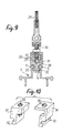
- Figures 9 and 10 show another fastening device designed to allow the attachment of another piece of equipment or accessory on a profile 1.
- it is a cable or d 'a hanger bar 29 which must be attached at an intermediate point the length of a profile 1.
- the corresponding fixing device comprises two hooking lugs 30 and 31 which both have, at their ends, a flange 32 intended to be hooked against a bead 5 of a lateral retaining groove 4 of the profile 1.
- the opposite ends of the two tabs 30 and 31 are intended to be fitted into one another after these tabs have been engaged in the groove 4 at points different from the length of the profile 1, so as to allow the passage of the hooking edges 32.
- the corresponding end of the tab 30 has a tapped hole 33 while the respective end of the tab 31 has a single smooth hole 34. When they are in concordance, these two holes are intended receiving a connecting screw 35 ensuring the fixing in place of a stirrup 36 carrying the accessory to be fixed, for example a cable 29 for hanger.
- this screw 35 ends in a conical tip 37 which is applied against seats 38 of the same shape, provided respectively on the internal face of the lug 31 and on the corresponding face of the lug 30.
- hooking lugs 30 and 31 can be engaged in a groove 4 in two in different rights therefrom to then be brought, by sliding, facing each other in their hooking position .
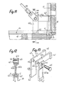
- FIGS. 11 to 13 show another fixing device intended to allow the fixing of one of the ends of a bracing bar 39 in the angle formed between two profiles 1e and 1f of the type of profiles 1.
- This device comprises two pairs of hooking lugs 40a, 40b on the one hand and 41a, 41b on the other hand, the ends of which are provided with beads 42 capable of being hooked against the beads 5 of the sides of the corresponding retaining groove 4 of the profiles 1st and 1st.
- one of the legs 40b of one of the two pairs forms one body with one of the legs 41b of the other pair, these two legs being constituted by the two branches of an L-shaped piece 43 As for the other two legs 40a and 41a, they are independent of each other. All these tabs have a hole 44 for the passage of a connecting pin 45 which is also engaged through similar holes provided in the two cheeks of a stirrup 46 to which the end of the bracing bar 39 is attached.
- these different fastening devices therefore have, as a common characteristic, the fact of each comprising two hooking lugs which are capable of being brought one after the other into their final position in which these two tabs, arranged one opposite the other, fill the corresponding retaining groove 4 with a profile 1 having their hooking rim in contact with the beads 5 retaining this groove.
- the sections 1a a serving as posts are fixed at their feet on assembly blocks 6a, one of which is shown in FIG. 14. This does not differ from the blocks assembly 6 already described only by the fact that its lower face 47 has a threaded circular opening 48 in place of the openings 8 provided in the other faces.
- this tapped opening 48 is screwed a ring 49 provided with a lower flange 49a. Inside this ring is screwed a stud 50 carried by a base 51.
- This mounting method makes it possible to adjust the height position of the block 6a, a lock nut 52 ensuring the blocking in the desired position.
- the base 51 of each block 6a is mounted on a rail 52 fixed to the ground and which has a general profile. U-shaped with flanges 53 projecting inwards.
- the base 51 carries one or more pads 54 engaged inside the corresponding rail 52 and which are connected to this base by bolts 55. The latter then make it possible to immobilize the base 51 in the position exact desired by tightening the flanges 53 between the pads 54 and the base 51.
- the openings 8 of the assembly blocks 6 can affect a polygonal contour other than a square contour. They may also have an oval outline.
- the attachment head 9 of the fixing end pieces 10 has the same contour to allow its introduction, after which, it suffices to rotate the corresponding profile on itself to obtain the attachment of this head to inside the corresponding assembly block.
- the openings 8 of these blocks could even have a circular contour provided that a certain number of radial notches are provided, in correspondence of which the attachment head 9 of the fixing end pieces would include retaining lugs, which would make it possible to achieve a bayonet attachment system.
- assembly blocks could have a shape other than cubic, to allow the arrangement of the profiles 1 in positions other than an orientation at 90 ° relative to each other, each of these blocks then comprising a series of faces oriented in the different directions provided for the corresponding profiles.
- the set of elements according to the invention can be used to produce three-dimensional structures intended to serve as a support for various layout elements, such as wall or floor elements, bleachers, exhibition stands etc ...
- This set can be applied in a wide variety of fields, in particular for the temporary development of exhibition spaces, or even for the layout of a living room, or a room in a sales store or even an office, etc ...
Landscapes
- Engineering & Computer Science (AREA)
- Architecture (AREA)
- Physics & Mathematics (AREA)
- Electromagnetism (AREA)
- Civil Engineering (AREA)
- Structural Engineering (AREA)
- General Engineering & Computer Science (AREA)
- Mechanical Engineering (AREA)
- Joining Of Building Structures In Genera (AREA)
- Freezers Or Refrigerated Showcases (AREA)
- Toys (AREA)
Claims (9)
Priority Applications (1)
| Application Number | Priority Date | Filing Date | Title |
|---|---|---|---|
| AT85402557T ATE42782T1 (de) | 1984-12-21 | 1985-12-19 | Einheit von konstruktionselementen zum bau von raeumlichkeiten fuer ausstellungen, zum wohnen oder geeignet fuer andere verwendungszwecke. |
Applications Claiming Priority (2)
| Application Number | Priority Date | Filing Date | Title |
|---|---|---|---|
| FR8419628 | 1984-12-21 | ||
| FR8419628A FR2575204B1 (fr) | 1984-12-21 | 1984-12-21 | Ensemble d'elements de construction pour l'amenagement d'espaces d'exposition, d'habitation ou affectes a d'autres usages |
Publications (2)
| Publication Number | Publication Date |
|---|---|
| EP0187100A1 EP0187100A1 (de) | 1986-07-09 |
| EP0187100B1 true EP0187100B1 (de) | 1989-05-03 |
Family
ID=9310875
Family Applications (1)
| Application Number | Title | Priority Date | Filing Date |
|---|---|---|---|
| EP85402557A Expired EP0187100B1 (de) | 1984-12-21 | 1985-12-19 | Einheit von Konstruktionselementen zum Bau von Räumlichkeiten für Ausstellungen, zum Wohnen oder geeignet für andere Verwendungszwecke |
Country Status (7)
| Country | Link |
|---|---|
| US (1) | US4646503A (de) |
| EP (1) | EP0187100B1 (de) |
| JP (1) | JPS61229044A (de) |
| AT (1) | ATE42782T1 (de) |
| CA (1) | CA1281162C (de) |
| DE (1) | DE3569948D1 (de) |
| FR (1) | FR2575204B1 (de) |
Cited By (1)
| Publication number | Priority date | Publication date | Assignee | Title |
|---|---|---|---|---|
| DE102015001945A1 (de) | 2015-02-16 | 2016-08-18 | Ellenberger & Poensgen Gmbh | Schutzschalter und Verfahren zu dessen Betrieb |
Families Citing this family (24)
| Publication number | Priority date | Publication date | Assignee | Title |
|---|---|---|---|---|
| DE3866022D1 (de) * | 1987-05-19 | 1991-12-12 | Astro Aerospace Corp | Verbindungsvorrichtung fuer stangen einer entfaltbaren konstruktion. |
| GB2228057A (en) * | 1989-02-11 | 1990-08-15 | Kwikform Ltd Gkn | Beam scaffold connector |
| GB2281083B (en) * | 1993-08-18 | 1998-03-18 | Fiona Milnes | Bayonet ring hub connector |
| FR2734339B1 (fr) * | 1995-05-19 | 1997-08-08 | Alugrip | Structure en reseau de mailles |
| CH705434B1 (de) * | 2000-01-05 | 2013-03-15 | Syma Intercontinental Sa | Würfelförmiges Profilelement und Profilleiste hierfür. |
| FR2823235B1 (fr) * | 2001-04-05 | 2005-02-11 | Jean Eudes Dufour | Dispositif d'assemblage de poutres |
| ITPD20050356A1 (it) * | 2005-12-05 | 2007-06-06 | Alu Spa | Dispositivo di fissaggio, particolarmente per il fissaggio su elementi a profilo scanalato |
| JP4895719B2 (ja) * | 2006-08-17 | 2012-03-14 | Ykk株式会社 | 連結具 |
| GB0623361D0 (en) * | 2006-11-23 | 2007-01-03 | Techna Display Ltd | Connector for use in display frames |
| US8627632B2 (en) | 2008-08-29 | 2014-01-14 | Werner Extrusion Solutions LLC | Node, apparatus, system and method regarding a frame support for solar mirrors |
| US8887471B2 (en) * | 2008-08-29 | 2014-11-18 | Werner Extrusion Solutions LLC | Strut, system and method for a solar mirror frame |
| WO2010024891A1 (en) | 2008-08-29 | 2010-03-04 | Werner Extrusion Solutions LLC | Solar trough frame, part and method |
| USD614481S1 (en) | 2009-04-30 | 2010-04-27 | Expo Dynamo (Systems) Ltd. | Framework connector |
| US11988415B2 (en) | 2009-08-26 | 2024-05-21 | Werner Extrusion Solutions, Llc | Solar mirror array system, methods and apparatuses thereto |
| GB2480475A (en) * | 2010-05-20 | 2011-11-23 | Tecna Display Ltd | Support bracket for use with a profiled beam of a display frame |
| DE202011002161U1 (de) * | 2011-01-31 | 2012-05-03 | Milos Concepts GmbH | Tragwerksystem |
| SG189568A1 (en) | 2011-10-10 | 2013-05-31 | Botak Sign Pte Ltd | A connector system for structural framework |
| CN104032828B (zh) * | 2014-03-20 | 2017-01-18 | 北京工业大学 | 一种工业化的模块式多高层装配式钢结构中心支撑体系 |
| CN106481623A (zh) * | 2016-07-21 | 2017-03-08 | 厦门上特展示系统工程有限公司 | 一种方管锁固机构 |
| NL2017798B1 (en) * | 2016-11-16 | 2018-05-25 | Mdlx B V | Modular building structure with reinforced beams, cuboid corner elements and connector elements |
| CN111350272B (zh) * | 2020-04-03 | 2024-07-23 | 何炬贤 | 一种可延展型模块化组合框架 |
| CN112854842A (zh) * | 2021-03-19 | 2021-05-28 | 中建四局第五建筑工程有限公司 | 一种带有防松装置的大型厂房钢结构 |
| GB202405892D0 (en) * | 2024-04-26 | 2024-06-12 | Mccreadie Rowland Timothy | Support frame joining system |
| WO2026033510A1 (en) * | 2024-08-06 | 2026-02-12 | Efar International Trade Ltd. | Modular joint system |
Family Cites Families (15)
| Publication number | Priority date | Publication date | Assignee | Title |
|---|---|---|---|---|
| US2192048A (en) * | 1937-09-11 | 1940-02-27 | Mueller Carl | Expansion coupling |
| US2519464A (en) * | 1947-02-03 | 1950-08-22 | Miner Inc W H | Center pin for body and truck bolsters |
| GB1021311A (en) * | 1961-01-26 | 1966-03-02 | Brockhouse Steel Structures Lt | Improvements in or relating to structural frameworks |
| DE1775597B1 (de) * | 1968-08-30 | 1971-10-14 | Josef Eiselt | Verbindung von Rohrstaeben zum Aufbau von Geruesten,Fachwerken,Regalen,Aufbaumoebeln u.dgl. |
| DE2100874A1 (de) * | 1971-01-09 | 1972-07-20 | Kretz, Erich, 4000 Düsseldorf | Trägerrost |
| SE369099B (de) * | 1971-12-17 | 1974-08-05 | R Haegglund | |
| CH561364A5 (de) * | 1973-04-03 | 1975-04-30 | Felix Andre | |
| FR2268970A1 (en) * | 1974-04-26 | 1975-11-21 | Technal International Sa | Profiled sections for partition and door frames - have longitudinal ribs with joining sliders with holes for fastening elements |
| US3982841A (en) * | 1975-12-08 | 1976-09-28 | Abraham Endzweig | Connecting apparatus for frame members |
| US4129975A (en) * | 1977-03-09 | 1978-12-19 | Matrix Toys, Inc. | Construction set having clip fasteners |
| US4102529A (en) * | 1977-05-06 | 1978-07-25 | Neblung Werner H | Railing system |
| US4122646A (en) * | 1977-06-08 | 1978-10-31 | Research-Cottrell, Inc. | Equilateral derrick structure |
| FR2513736B1 (fr) * | 1981-09-29 | 1986-04-04 | Souchal Jean | Structure constituee de barres assemblees entre elles par des noeuds d'assemblage |
| EP0080556B1 (de) * | 1981-11-26 | 1986-10-22 | Hestex Systems B.V. | Einschiebbares Klemmschloss zur lösbaren Verbindung von zwei Bauelementen |
| US4556337A (en) * | 1983-03-07 | 1985-12-03 | Framelock International Pty. Limited | Connector for framing system |
-
1984
- 1984-12-21 FR FR8419628A patent/FR2575204B1/fr not_active Expired
-
1985
- 1985-12-19 AT AT85402557T patent/ATE42782T1/de not_active IP Right Cessation
- 1985-12-19 EP EP85402557A patent/EP0187100B1/de not_active Expired
- 1985-12-19 DE DE8585402557T patent/DE3569948D1/de not_active Expired
- 1985-12-20 CA CA000498332A patent/CA1281162C/en not_active Expired - Lifetime
- 1985-12-20 JP JP60287616A patent/JPS61229044A/ja active Pending
- 1985-12-23 US US06/812,380 patent/US4646503A/en not_active Expired - Fee Related
Cited By (1)
| Publication number | Priority date | Publication date | Assignee | Title |
|---|---|---|---|---|
| DE102015001945A1 (de) | 2015-02-16 | 2016-08-18 | Ellenberger & Poensgen Gmbh | Schutzschalter und Verfahren zu dessen Betrieb |
Also Published As
| Publication number | Publication date |
|---|---|
| FR2575204A1 (fr) | 1986-06-27 |
| US4646503A (en) | 1987-03-03 |
| EP0187100A1 (de) | 1986-07-09 |
| ATE42782T1 (de) | 1989-05-15 |
| CA1281162C (en) | 1991-03-12 |
| DE3569948D1 (en) | 1989-06-08 |
| JPS61229044A (ja) | 1986-10-13 |
| FR2575204B1 (fr) | 1988-02-12 |
Similar Documents
| Publication | Publication Date | Title |
|---|---|---|
| EP0187100B1 (de) | Einheit von Konstruktionselementen zum Bau von Räumlichkeiten für Ausstellungen, zum Wohnen oder geeignet für andere Verwendungszwecke | |
| CA1335498C (fr) | Dispositif d'assemblage pour elements demontables ou modulaires | |
| FR2612539A1 (fr) | Poutrelle de support de plafond | |
| EP2399823B1 (de) | Befestigungseinheit, die Rampen für die Fixierung von Systemen in einem Luftfahrzeug umfasst | |
| CH650315A5 (fr) | Organe d'assemblage et dispositif d'assemblage comportant au moins deux organes d'assemblage. | |
| EP0172111A1 (de) | Winkelstütze für eine Ablage, Verkleidung usw. und daraus gebautes Möbel | |
| EP3296484A1 (de) | Längenregulierbare verstrebungsvorrichtung | |
| FR2547848A1 (fr) | Paroi prefabriquee destinee a la construction de maisons et autres batiments, et son procede de fabrication | |
| FR3036446A1 (fr) | Dispositif d'accrochage d'un panneau a une structure porteuse | |
| CH409278A (fr) | Ossature métallique | |
| FR2587053A1 (fr) | Elements de construction, notamment pour la fabrication de cloisons et d'encadrements | |
| WO1989000634A1 (fr) | Dispositif de fixation ponctuelle d'elements presentant un bord, notamment de plaques sur une structure support | |
| FR2519052A1 (fr) | Balustrade en elements prefabriques reglables pour la protection et la delimitation de surfaces planes et inclinees | |
| FR2461140A1 (fr) | Ensemble de menuiserie modulaire, destine notamment a l'installation de stands d'exposition ou de bureaux | |
| FR2612548A1 (fr) | Ensemble d'elements de construction pour l'amenagement d'espaces d'exposition ou autres locaux | |
| EP1306498A1 (de) | Befestigungseinrichtung für Platten, insbesondere für Verandadachplatten und Veranda mit einer solcher Einrichtung | |
| WO1990015906A1 (fr) | Ensemble d'elements modulaires emboitables pour la construction de cloisons | |
| FR2734339A1 (fr) | Structure en reseau de mailles | |
| EP0651111B1 (de) | Montage- und Haltevorrichtung eines Geländerholmes | |
| EP3762918B1 (de) | Verfahren zur montage einer flexiblen, über einen halterahmen aufgespannten abdeckung und halterahmen zur durchführung eines solchen verfahrens | |
| FR2754992A1 (fr) | Profile angulaire multifonctions reunissant les montants de mobilier | |
| EP1386304B1 (de) | Profil und satz von mehreren elementen mit einem oder mehreren solcher profilen | |
| FR2473137A1 (fr) | Dispositif d'assemblage de panneaux a double revetement | |
| FR2560940A1 (fr) | Perfectionnement aux dispositifs d'assemblage | |
| EP4223950A1 (de) | Verfahren zur montage eines bauteils |
Legal Events
| Date | Code | Title | Description |
|---|---|---|---|
| PUAI | Public reference made under article 153(3) epc to a published international application that has entered the european phase |
Free format text: ORIGINAL CODE: 0009012 |
|
| AK | Designated contracting states |
Kind code of ref document: A1 Designated state(s): AT BE CH DE FR GB IT LI LU NL SE |
|
| 17P | Request for examination filed |
Effective date: 19861222 |
|
| 17Q | First examination report despatched |
Effective date: 19880303 |
|
| ITF | It: translation for a ep patent filed | ||
| GRAA | (expected) grant |
Free format text: ORIGINAL CODE: 0009210 |
|
| RAP3 | Party data changed (applicant data changed or rights of an application transferred) |
Owner name: BUREAU TECHNIQUE DU BATIMENT D'AMENAGEMENTS ET DE Owner name: FOUGERAS LAVERGNOLLE, ARNAUD Owner name: BRULLMANN, CUNO |
|
| AK | Designated contracting states |
Kind code of ref document: B1 Designated state(s): AT BE CH DE FR GB IT LI LU NL SE |
|
| PG25 | Lapsed in a contracting state [announced via postgrant information from national office to epo] |
Ref country code: SE Effective date: 19890503 Ref country code: NL Effective date: 19890503 Ref country code: GB Effective date: 19890503 Ref country code: AT Effective date: 19890503 |
|
| REF | Corresponds to: |
Ref document number: 42782 Country of ref document: AT Date of ref document: 19890515 Kind code of ref document: T |
|
| REF | Corresponds to: |
Ref document number: 3569948 Country of ref document: DE Date of ref document: 19890608 |
|
| NLV1 | Nl: lapsed or annulled due to failure to fulfill the requirements of art. 29p and 29m of the patents act | ||
| GBV | Gb: ep patent (uk) treated as always having been void in accordance with gb section 77(7)/1977 [no translation filed] | ||
| PG25 | Lapsed in a contracting state [announced via postgrant information from national office to epo] |
Ref country code: LU Free format text: LAPSE BECAUSE OF NON-PAYMENT OF DUE FEES Effective date: 19891231 |
|
| PLBE | No opposition filed within time limit |
Free format text: ORIGINAL CODE: 0009261 |
|
| STAA | Information on the status of an ep patent application or granted ep patent |
Free format text: STATUS: NO OPPOSITION FILED WITHIN TIME LIMIT |
|
| 26N | No opposition filed | ||
| ITTA | It: last paid annual fee | ||
| PGFP | Annual fee paid to national office [announced via postgrant information from national office to epo] |
Ref country code: LU Payment date: 19901231 Year of fee payment: 6 |
|
| PGFP | Annual fee paid to national office [announced via postgrant information from national office to epo] |
Ref country code: BE Payment date: 19910114 Year of fee payment: 6 |
|
| PGFP | Annual fee paid to national office [announced via postgrant information from national office to epo] |
Ref country code: DE Payment date: 19910130 Year of fee payment: 6 |
|
| PGFP | Annual fee paid to national office [announced via postgrant information from national office to epo] |
Ref country code: CH Payment date: 19910308 Year of fee payment: 6 |
|
| EPTA | Lu: last paid annual fee | ||
| PG25 | Lapsed in a contracting state [announced via postgrant information from national office to epo] |
Ref country code: LI Effective date: 19911231 Ref country code: CH Effective date: 19911231 Ref country code: BE Effective date: 19911231 |
|
| BERE | Be: lapsed |
Owner name: BUREAU TECHNIQUE DU BATIMENT D'AMENAGEMENTS ET DE Effective date: 19911231 Owner name: FOUGERAS LAVERGNOLLE ARNAUD Effective date: 19911231 Owner name: BRULLMANN CUNO Effective date: 19911231 |
|
| REG | Reference to a national code |
Ref country code: CH Ref legal event code: PL |
|
| PG25 | Lapsed in a contracting state [announced via postgrant information from national office to epo] |
Ref country code: DE Effective date: 19920901 |
|
| PGFP | Annual fee paid to national office [announced via postgrant information from national office to epo] |
Ref country code: FR Payment date: 19951228 Year of fee payment: 11 |
|
| PG25 | Lapsed in a contracting state [announced via postgrant information from national office to epo] |
Ref country code: FR Effective date: 19970829 |
|
| REG | Reference to a national code |
Ref country code: FR Ref legal event code: ST |