EP0187148B1 - Rotationsmaschine - Google Patents
Rotationsmaschine Download PDFInfo
- Publication number
- EP0187148B1 EP0187148B1 EP85902631A EP85902631A EP0187148B1 EP 0187148 B1 EP0187148 B1 EP 0187148B1 EP 85902631 A EP85902631 A EP 85902631A EP 85902631 A EP85902631 A EP 85902631A EP 0187148 B1 EP0187148 B1 EP 0187148B1
- Authority
- EP
- European Patent Office
- Prior art keywords
- rotor
- curve
- axis
- points
- machine according
- Prior art date
- Legal status (The legal status is an assumption and is not a legal conclusion. Google has not performed a legal analysis and makes no representation as to the accuracy of the status listed.)
- Expired - Lifetime
Links
Images




Classifications
-
- F—MECHANICAL ENGINEERING; LIGHTING; HEATING; WEAPONS; BLASTING
- F01—MACHINES OR ENGINES IN GENERAL; ENGINE PLANTS IN GENERAL; STEAM ENGINES
- F01C—ROTARY-PISTON OR OSCILLATING-PISTON MACHINES OR ENGINES
- F01C1/00—Rotary-piston machines or engines
- F01C1/30—Rotary-piston machines or engines having the characteristics covered by two or more groups F01C1/02, F01C1/08, F01C1/22, F01C1/24 or having the characteristics covered by one of these groups together with some other type of movement between co-operating members
- F01C1/40—Rotary-piston machines or engines having the characteristics covered by two or more groups F01C1/02, F01C1/08, F01C1/22, F01C1/24 or having the characteristics covered by one of these groups together with some other type of movement between co-operating members having the movement defined in group F01C1/08 or F01C1/22 and having a hinged member
- F01C1/44—Rotary-piston machines or engines having the characteristics covered by two or more groups F01C1/02, F01C1/08, F01C1/22, F01C1/24 or having the characteristics covered by one of these groups together with some other type of movement between co-operating members having the movement defined in group F01C1/08 or F01C1/22 and having a hinged member with vanes hinged to the inner member
Definitions
- This invention relates to a rotary machine which exploits inner cyclic variable volumes.
- Such an engine as described in the preamble of claim 1 is shown in FR-A-2 235 268.
- the rotary machine according to the invention is composed of:
- the rotor is composed of N r sides (N r ⁇ 1) which have N e equal ends with equal surfaces E.
- N e surfaces E with plane r are N e equal circles or radius r with centres P i which are points of respective axes Y I .
- Points P run on a curve R N which characterises the rotary machine, as in the Wankel engine, the geometry of which is based on a curve R N , which is a trochoid curve.
- Perimetral surfaces M or stator cavity U is the external envelope of the rotor surfaces E, which slide round touching surface M along N e equal lines.
- the present invention has rotor points P, running on trajectories R N different from the above trajectories and described in claim 1.
- the present invention can work as a pump, compressor, motor, engine, valve, distributor or hydraulic joint; it may burn fuel for heat and/or electricity as in magneto-hydrodynamic generators; it can also be used as a compressor and/or booster for thermic motors with inner reactive combustion.
- Stator body 1 has an inner cavity with perimetral surface M.
- Transmission shaft 14 has rotary axis Y c which intersects plane r orthogonally at point C.
- the rotor touches contour M by interposed rings 10 of radius r.
- Cylinders 4 and rings 10 have common axis Y I .
- An non-extensible connection (bar 7) joins pivot/s 6 centered in points D with transmission shaft 14 ( Figures 2 and 3).
- Rotor sides or pistons 5 have equal height, their flat bases are parallel to plane r and slip over the stator bases.
- External surface 9 of each piston 5 corresponds to one rotating chamber V.
- Integer N is modulus of curve R N .
- Each chamber V is defined by piston wall 9, two surfaces E of rings 10, cylinder M, and two stator bases.
- N r pistons 5 form one chamber Z of variable volume Z ( ⁇ ) .
- Chamber Z is defined by N e surfaces 13 of pistons 5, N e surfaces E or rings 10 and the two stator bases; it pumps a fluid which enters and exits through holding valves (not shown in figures). Volumes V ( ⁇ ) and Z ( ⁇ ) are defined in any position of the rotor. The fluid in chamber Z cools and lubricates the machine and may feed a hydraulic accumulator (not shown in figures).
- the rotor can be made by packing thin metal sheets together. It may also be an open prismatic structure, and composed of only one side without hinges, or composed of solid cylinders only. Chambers V and Z may be interconnected.
- Figure 4 shows a schematic view of a coaxial cyclic volume machine composed of one rotating cyclic volume machine as a compressor, and one rotating cyclic volume machine as an engine, with one common transmission shaft 14 and one common stator base between them.
- Operating fluid enters 3 and flows through the two transfer channels 23 bored in the common base, and is controlled by engine rotor P 1 P 2 P 3 p 4 .
- the fluid enters the two opposite combustion chambers, where it is further compressed for combustion. Waste gases are discharged through channels 24 bored in the stator base of the engine side. Maximum fluid compression occurs in engine area 11, where ignition takes place and expansion of gases rotates the polygonal structure of the engine and the compressor.
- cooling fluid enters the Z area of the compressor, passing through the Z area of the engine, and powers a hydraulic accumulator which is also a heat radiator (not shown).
- Axes X 1 and X 2 form angle ⁇ on projection plane. Angle ⁇ is important for precompression of the engine when the axis of channel 23 is parallel to axis Y c .
- Modulus N conditions the choice of the maximum number N r of rotor sides 1 ⁇ Nr ⁇ N which have number N e of equal cylindrical ends E; 2 ⁇ Ne ⁇ 2(Nr ⁇ 1).
- Rotor points-P, of the present invention run along curve R N belonging to a new class of curves called ROTOID CURVES with the peculiar geometrical property called invariant length W.
- Points Fi 1 to N, lie on curve L and distributed in infinite groups of points, each group consisting of N points F 1 , ... F N , N ⁇ 2, (modulus N is constant integer).
- Axis Y c is orthogonal to a plane r in a point C inside the region defined by curve L. Point C is distinct from baricentre 0 of N-polygon F i .
- L being a closed curve, function f ( ⁇ ) will be defined for any value of a; then f ( ⁇ ) is a continuous function.
- a system of N equalities expressed by f, a, ⁇ 1 , ⁇ 2 , ... ⁇ N is valid according to Carnot's theorem, to determine side length W ( ⁇ )
- W is the side measure of one family of equilateral N-polygons P i .
- Figure 1 shows a machine in the general case: rotor axis Y o is orthogonal to reference plane r in baricentre O. Baricentre 0 is different from pole C, Y o //Y c . Angles P i P ⁇ i+1 P i+2 vary with anomaly a.
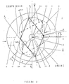
- Machines with rotor vertices on points Q i are characterized by the non-deformability of the rotor and rotoid curve R N is defined by radius CQ, Figure 5, angles Q i Q ⁇ i+1 Q i+2 are constant.
- Machines characterized by these trajectories of rotor vertices have axis Y o coinciding with axis Y c and with the symmetry axis of stator cavity U.
- equations g ( ⁇ ) of formula (2) have the property of invariant length W:
- equation g ( ⁇ ) defines rotoid curves R N of the machines shown in Figure 3, in which the four points P, are vertices of a family of rhombuses P, with baricentre in pole C. Vertices P, are on rotoid curve R 4 defined by:
- An inextensible connection (bar 7) joins the middle points of rotor sides P i P i +1 and P i+2 P i+3 to transmission shaft 14.
- bar 7 has a centre of rotation coinciding with baricentre 0 of rhombus P i .
- point D need not be on a circumference.
- the rotor of the cyclic volume machine may be used as a tool to rectify perimetral surface M of inner stator cavity U.
- Perimetral surface M of stator cavity U may be radiused with stator bases according to a complementary profile to the profile of rotor surface E.
Landscapes
- Engineering & Computer Science (AREA)
- Mechanical Engineering (AREA)
- General Engineering & Computer Science (AREA)
- Applications Or Details Of Rotary Compressors (AREA)
- Rotary Pumps (AREA)
- Permanent Magnet Type Synchronous Machine (AREA)
- Lubrication Of Internal Combustion Engines (AREA)
- Iron Core Of Rotating Electric Machines (AREA)
- Lasers (AREA)
- Organic Low-Molecular-Weight Compounds And Preparation Thereof (AREA)
- Lubricants (AREA)
- Soil Working Implements (AREA)
- Centrifugal Separators (AREA)
- Structures Of Non-Positive Displacement Pumps (AREA)
- Connection Of Motors, Electrical Generators, Mechanical Devices, And The Like (AREA)
- Motor Or Generator Cooling System (AREA)
Claims (7)



Applications Claiming Priority (1)
| Application Number | Priority Date | Filing Date | Title |
|---|---|---|---|
| IT41597/84A IT1180993B (it) | 1984-06-22 | 1984-06-22 | Macchina volumetrica rotativa |
Publications (2)
| Publication Number | Publication Date |
|---|---|
| EP0187148A1 EP0187148A1 (de) | 1986-07-16 |
| EP0187148B1 true EP0187148B1 (de) | 1990-05-23 |
Family
ID=11251765
Family Applications (1)
| Application Number | Title | Priority Date | Filing Date |
|---|---|---|---|
| EP85902631A Expired - Lifetime EP0187148B1 (de) | 1984-06-22 | 1985-06-03 | Rotationsmaschine |
Country Status (6)
| Country | Link |
|---|---|
| EP (1) | EP0187148B1 (de) |
| AT (1) | ATE53098T1 (de) |
| AU (1) | AU4436185A (de) |
| DE (1) | DE3577900D1 (de) |
| IT (1) | IT1180993B (de) |
| WO (1) | WO1986000370A1 (de) |
Cited By (1)
| Publication number | Priority date | Publication date | Assignee | Title |
|---|---|---|---|---|
| EP1991760A1 (de) * | 2005-12-01 | 2008-11-19 | CONTIERO, Italo | Drehflügel-verdrängermaschine |
Families Citing this family (5)
| Publication number | Priority date | Publication date | Assignee | Title |
|---|---|---|---|---|
| US7178502B2 (en) | 2001-06-05 | 2007-02-20 | Paul D. Okulov | Balanced rotary internal combustion engine or cycling volume machine |
| US6899075B2 (en) * | 2002-03-22 | 2005-05-31 | Roxan Saint-Hilaire | Quasiturbine (Qurbine) rotor with central annular support and ventilation |
| FR2936272B1 (fr) | 2008-09-22 | 2012-07-13 | Vincent Genissieux | Machine rotative a losange deformable multifonctions |
| CA2851716C (en) | 2011-10-14 | 2016-04-12 | Gullivert Technologies Inc. | Belt and support for a rotor mechanism in a rotary apparatus and rotary apparatus comprising same |
| FR3005106B1 (fr) | 2013-04-25 | 2017-11-24 | Jean Pierre Ambert | Machine volumique rotative a trois pistons |
Family Cites Families (7)
| Publication number | Priority date | Publication date | Assignee | Title |
|---|---|---|---|---|
| GB191026118A (en) * | 1910-11-09 | 1911-01-12 | Henry John Hudson | Improvements in Rotary Internal Combustion Engines. |
| GB789375A (en) * | 1953-04-29 | 1958-01-22 | Henri Delmer | A pump or engine of the oscillating-vane type |
| US3295505A (en) * | 1963-05-31 | 1967-01-03 | Jordan Alfred | Rotary piston apparatus |
| FR1376285A (fr) * | 1963-12-04 | 1964-10-23 | Moteur volumétrique à combustion interne | |
| DE1526408A1 (de) * | 1965-06-09 | 1970-07-30 | Politechnika Warszawska | Verbrennungsmotor mit umlaufenden,eine geschlossene Kette bildenden,Kolben |
| ES416371A1 (es) * | 1973-06-27 | 1976-05-16 | Martin Artajo | Maquina de embolos giratorios articulados. |
| FR2493397A1 (fr) * | 1980-11-03 | 1982-05-07 | Ambert Jean Pierre | Moteur rotatif |
-
1984
- 1984-06-22 IT IT41597/84A patent/IT1180993B/it active
-
1985
- 1985-06-03 AU AU44361/85A patent/AU4436185A/en not_active Abandoned
- 1985-06-03 DE DE8585902631T patent/DE3577900D1/de not_active Expired - Lifetime
- 1985-06-03 EP EP85902631A patent/EP0187148B1/de not_active Expired - Lifetime
- 1985-06-03 AT AT85902631T patent/ATE53098T1/de not_active IP Right Cessation
- 1985-06-03 WO PCT/IT1985/000005 patent/WO1986000370A1/en not_active Ceased
Non-Patent Citations (1)
| Title |
|---|
| I. Contiero, L. Beghi, "Class of algebraic curves passing through cyclic points" 16.03.85, p. 15 (published privately by I. Contiero and L. Beghi) * |
Cited By (1)
| Publication number | Priority date | Publication date | Assignee | Title |
|---|---|---|---|---|
| EP1991760A1 (de) * | 2005-12-01 | 2008-11-19 | CONTIERO, Italo | Drehflügel-verdrängermaschine |
Also Published As
| Publication number | Publication date |
|---|---|
| IT1180993B (it) | 1987-09-23 |
| DE3577900D1 (de) | 1990-06-28 |
| IT8441597A1 (it) | 1985-12-22 |
| IT8441597A0 (it) | 1984-06-22 |
| WO1986000370A1 (en) | 1986-01-16 |
| AU4436185A (en) | 1986-01-24 |
| ATE53098T1 (de) | 1990-06-15 |
| EP0187148A1 (de) | 1986-07-16 |
Similar Documents
| Publication | Publication Date | Title |
|---|---|---|
| US5431551A (en) | Rotary positive displacement device | |
| US3560119A (en) | Fluid pump or motor | |
| US4300874A (en) | Rotary machine with lenticular rotor and a circular guide member therefor | |
| US3289654A (en) | Rotary piston type internal combustion engine | |
| US5171142A (en) | Rotary displacement machine with cylindrical pretension on disc-shaped partition | |
| US5391067A (en) | Rotary fluid displacement device | |
| HU210369B (en) | Machine with rotating blades | |
| US8047824B2 (en) | Vane machine with stationary and rotating cylinder parts | |
| US3799706A (en) | Rotor assembly for a rotary machine | |
| EP0187148B1 (de) | Rotationsmaschine | |
| US7488166B2 (en) | Rotary volumetric machine | |
| US4605361A (en) | Oscillating vane rotary pump or motor | |
| US5288217A (en) | Cyclic volume machine | |
| US4239466A (en) | Rotary machine with adjustable means for its eccentric rotor | |
| CA2162678A1 (en) | Rotary vane mechanical power system | |
| US3748068A (en) | Rotary vane device | |
| US3794450A (en) | Rotary machine apex seal | |
| US5071330A (en) | Roller-vane hydraulic machine | |
| US4370111A (en) | Rotary pump or motor with drive rollers and free-floating rollers | |
| US3349757A (en) | Rotary positive displacement machine | |
| US5429083A (en) | Rotary internal combustion twin engine | |
| US3989427A (en) | Rotary fluid handling device | |
| RU2082020C1 (ru) | Роторная объемная гидропневмомашина | |
| US4173439A (en) | Apparatus having expanding and contracting chamber | |
| CN1015483B (zh) | 球形转子泵和球形转子机 |
Legal Events
| Date | Code | Title | Description |
|---|---|---|---|
| PUAI | Public reference made under article 153(3) epc to a published international application that has entered the european phase |
Free format text: ORIGINAL CODE: 0009012 |
|
| AK | Designated contracting states |
Kind code of ref document: A1 Designated state(s): AT BE CH DE FR GB IT LI LU NL SE |
|
| 17P | Request for examination filed |
Effective date: 19860326 |
|
| 17Q | First examination report despatched |
Effective date: 19870218 |
|
| GRAA | (expected) grant |
Free format text: ORIGINAL CODE: 0009210 |
|
| AK | Designated contracting states |
Kind code of ref document: B1 Designated state(s): AT BE CH DE FR GB IT LI LU NL SE |
|
| PG25 | Lapsed in a contracting state [announced via postgrant information from national office to epo] |
Ref country code: NL Effective date: 19900523 Ref country code: BE Effective date: 19900523 Ref country code: AT Effective date: 19900523 |
|
| REF | Corresponds to: |
Ref document number: 53098 Country of ref document: AT Date of ref document: 19900615 Kind code of ref document: T |
|
| ITF | It: translation for a ep patent filed | ||
| PGFP | Annual fee paid to national office [announced via postgrant information from national office to epo] |
Ref country code: CH Payment date: 19900620 Year of fee payment: 6 |
|
| REF | Corresponds to: |
Ref document number: 3577900 Country of ref document: DE Date of ref document: 19900628 |
|
| PG25 | Lapsed in a contracting state [announced via postgrant information from national office to epo] |
Ref country code: LU Free format text: LAPSE BECAUSE OF NON-PAYMENT OF DUE FEES Effective date: 19900630 |
|
| PGFP | Annual fee paid to national office [announced via postgrant information from national office to epo] |
Ref country code: NL Payment date: 19900630 Year of fee payment: 6 |
|
| ET | Fr: translation filed | ||
| PGFP | Annual fee paid to national office [announced via postgrant information from national office to epo] |
Ref country code: SE Payment date: 19900803 Year of fee payment: 6 |
|
| NLV1 | Nl: lapsed or annulled due to failure to fulfill the requirements of art. 29p and 29m of the patents act | ||
| PLBE | No opposition filed within time limit |
Free format text: ORIGINAL CODE: 0009261 |
|
| STAA | Information on the status of an ep patent application or granted ep patent |
Free format text: STATUS: NO OPPOSITION FILED WITHIN TIME LIMIT |
|
| 26N | No opposition filed | ||
| PG25 | Lapsed in a contracting state [announced via postgrant information from national office to epo] |
Ref country code: SE Effective date: 19910604 |
|
| PG25 | Lapsed in a contracting state [announced via postgrant information from national office to epo] |
Ref country code: LI Effective date: 19910630 Ref country code: CH Effective date: 19910630 |
|
| REG | Reference to a national code |
Ref country code: CH Ref legal event code: PL |
|
| PGFP | Annual fee paid to national office [announced via postgrant information from national office to epo] |
Ref country code: GB Payment date: 19930625 Year of fee payment: 9 |
|
| PG25 | Lapsed in a contracting state [announced via postgrant information from national office to epo] |
Ref country code: GB Effective date: 19940603 |
|
| PGFP | Annual fee paid to national office [announced via postgrant information from national office to epo] |
Ref country code: FR Payment date: 19940603 Year of fee payment: 10 |
|
| PGFP | Annual fee paid to national office [announced via postgrant information from national office to epo] |
Ref country code: DE Payment date: 19940620 Year of fee payment: 10 |
|
| EUG | Se: european patent has lapsed |
Ref document number: 85902631.2 Effective date: 19920109 |
|
| GBPC | Gb: european patent ceased through non-payment of renewal fee |
Effective date: 19940603 |
|
| PG25 | Lapsed in a contracting state [announced via postgrant information from national office to epo] |
Ref country code: FR Effective date: 19960229 |
|
| PG25 | Lapsed in a contracting state [announced via postgrant information from national office to epo] |
Ref country code: DE Effective date: 19960301 |
|
| REG | Reference to a national code |
Ref country code: FR Ref legal event code: ST |