EP0187244A1 - Dispositif de fixation résistant aux vibrations pour surfaces douces - Google Patents
Dispositif de fixation résistant aux vibrations pour surfaces douces Download PDFInfo
- Publication number
- EP0187244A1 EP0187244A1 EP85115065A EP85115065A EP0187244A1 EP 0187244 A1 EP0187244 A1 EP 0187244A1 EP 85115065 A EP85115065 A EP 85115065A EP 85115065 A EP85115065 A EP 85115065A EP 0187244 A1 EP0187244 A1 EP 0187244A1
- Authority
- EP
- European Patent Office
- Prior art keywords
- teeth
- self
- crest
- locking
- fastener
- Prior art date
- Legal status (The legal status is an assumption and is not a legal conclusion. Google has not performed a legal analysis and makes no representation as to the accuracy of the status listed.)
- Granted
Links
- 230000035515 penetration Effects 0.000 claims abstract description 11
- 229910000975 Carbon steel Inorganic materials 0.000 abstract description 2
- 229910052782 aluminium Inorganic materials 0.000 abstract description 2
- 239000007779 soft material Substances 0.000 abstract description 2
- 230000013011 mating Effects 0.000 description 7
- 230000000694 effects Effects 0.000 description 3
- 230000001154 acute effect Effects 0.000 description 1
- 230000002411 adverse Effects 0.000 description 1
- 230000009286 beneficial effect Effects 0.000 description 1
- 239000010962 carbon steel Substances 0.000 description 1
- 238000010276 construction Methods 0.000 description 1
- 230000000149 penetrating effect Effects 0.000 description 1
- 230000001105 regulatory effect Effects 0.000 description 1
- 238000000926 separation method Methods 0.000 description 1
Images

Classifications
-
- F—MECHANICAL ENGINEERING; LIGHTING; HEATING; WEAPONS; BLASTING
- F16—ENGINEERING ELEMENTS AND UNITS; GENERAL MEASURES FOR PRODUCING AND MAINTAINING EFFECTIVE FUNCTIONING OF MACHINES OR INSTALLATIONS; THERMAL INSULATION IN GENERAL
- F16B—DEVICES FOR FASTENING OR SECURING CONSTRUCTIONAL ELEMENTS OR MACHINE PARTS TOGETHER, e.g. NAILS, BOLTS, CIRCLIPS, CLAMPS, CLIPS OR WEDGES; JOINTS OR JOINTING
- F16B39/00—Locking of screws, bolts or nuts
- F16B39/22—Locking of screws, bolts or nuts in which the locking takes place during screwing down or tightening
- F16B39/28—Locking of screws, bolts or nuts in which the locking takes place during screwing down or tightening by special members on, or shape of, the nut or bolt
- F16B39/282—Locking by means of special shape of work-engaging surfaces, e.g. notched or toothed nuts
-
- Y—GENERAL TAGGING OF NEW TECHNOLOGICAL DEVELOPMENTS; GENERAL TAGGING OF CROSS-SECTIONAL TECHNOLOGIES SPANNING OVER SEVERAL SECTIONS OF THE IPC; TECHNICAL SUBJECTS COVERED BY FORMER USPC CROSS-REFERENCE ART COLLECTIONS [XRACs] AND DIGESTS
- Y10—TECHNICAL SUBJECTS COVERED BY FORMER USPC
- Y10S—TECHNICAL SUBJECTS COVERED BY FORMER USPC CROSS-REFERENCE ART COLLECTIONS [XRACs] AND DIGESTS
- Y10S411/00—Expanded, threaded, driven, headed, tool-deformed, or locked-threaded fastener
- Y10S411/91—Antitamper means
- Y10S411/911—One-way drive
Definitions
- the present invention relates to self-locking fasteners and, in particular, to bolts, nuts, washers and the like having serrated bearing surfaces that provide resistance against the fastener becoming loosened unintentionally after it has been seated.
- the self-locking fastener of the present invention can be used to particular advantage for workpieces having relatively soft bearing surfaces whereby marring of the workpiece surface is minimized.
- a serious problem in joints secured together by threaded members is the possibility of joint separation due to a nut backing-off from a bolt or a bolt backing-out from a nut or other internally threaded member. Generally, this result can occur when the joint is subjected to vibrations.
- a similar improved fastener is also disclosed ?#4 commonly assigned U.S. Patent 3,825,051.
- This patent discloses a self-locking fastener having a polygon shaped workpiece bearing surface, such as a hex-head, where the serrated segment is formed within an annular segment so that circumferentially discontinuous smooth-faced outer bearing surfaces are formed across adjacent flats of the polygon configuration.
- the self-locking fastener of the present invention has a bearing surface with a plurality of serrations.
- the serrations when viewed along a cylinder concentric with the longitudinal axis of the fastener have the appearance of teeth.
- Between two teeth are a plurality of intermediate surfaces.
- the level of the intermediata surfaces, relative to the tceth, is between the crest and root of the teeth.
- an intermediate surface comprises an inclined plane starting at the crest of a tooth and proceeding downward to an intermediate level forming the intermediate surface, which can be considered generally parallel to the bearing surface, and then a second inclined plane extending downward from the intermediate, generally parallel surface to the root of the tooth.
- the intermediate surface reduces the marring of the workpiece by the teeth, yet sufficient resistance to vibration exists to prevent unintentional loosening of the fastener.
- a self-locking bolt constructed in accordance with the present invention includes a threaded shank 10, and a bolt head 11 at one end of shank 10.
- Bolt head 11 has a bearing flange 12.
- the bearing surface of flange 12, that is the surface to be placed in bearing contact against a workpiece (not shown), is provided with a plurality of outwardly disposed serrations 13.
- the serrations form sets of preferably two, for example serrations 14, which are parallel to each other leaving a wedge-shaped portion, for example 15, between the sets.
- Serration sets are defined as the surfaces represented in Figure 1 by four parallel lines.
- the bearing surface of flange 12 may include a plurality of radially disposed serrations rather than the parallel serration sets 14.
- bolt head 11 is at one end of threaded shank 10 and includes bearing flange 12.
- the bearing surface of flange 12 has, in this embodiment, outwardly disposed serrations.
- a downwardly inclined surface 17 starts at crest 16 and ends at one end of an intermediate parallel surface 18.
- Surface 18 can be considered generally parallel to the bearing surface of flange 12 or the non-bearing top surface 19 of flange 12.
- a second downwardly inclined surface 20 starts at the other end of parallel surface 18 and extends downwardly to a root 21 of the next tooth.
- Root 21 of the next tooth is connected by a wall 22, which is generally parallel to the longitudinal axis of the bolt, to the crest 24 of that tooth. Because, the serrations in this embodiment are parallel to each other, a pie-shaped wedge 23 separates successive parallel sets. Three pie-shaped wedges 23 are shown to illustrate this feature of the first embodiment. Each pie-shaped wedge 23 is at the same plane as root 21. Although wall 22 can generally be considered to be 90° to the plane of the bearing surface, variations from 90° are acceptable.
- Figure 3 is an enlarged cross sectional view of one set of serrations shown in Figure 2.
- downwardly inclined surface 17 proceeds to one end of intermediate parallel surface 18.
- surface 18 is generally parallel to bearing flange 12.
- Surface 18 is at a shallower depth, compared to crests 16 or 24, than the greater depth of root 21.
- a downwardly inclined surface 20 extends to root 21 of the adjacent tooth.
- Wall 22 extends from root 21 to crest 24 of the adjacent tooth.
- Surfaces 17, 18, 20, 21 and 22 along with crest 16 can be considered as one set of serrations. When viewed at a right angle to surface 18, the set consists of four parallel lines.
- Figure 3 also shows another feature of the present embodiment of the invention.
- Root 21 is connected to wall 22 by a radius or fillet 25, which is not considered essential to the present invention.
- Crests 16 and 24 are also preferably radiused rather than having sharp edges.
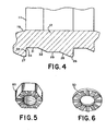
- Figure 4 is an enlarged cross sectional view of one set of serrations of another embodiment of the invention.
- the embodiment of Figure 4 differs from the one shown in Figure 3 in that crests 26 and 27 of the teeth are truncated with small flats.
- a downwardly inclined surface 28 starts at truncated crest 26 and extends to one end of an intermediate surface 29, that is generaly parallel to the bearing surface of flange 12.
- Surface 29 is at a level between that of crest 26 and a root 31.
- Another downwardly inclined surface 32 begins at the other end of surface 29 and extends to root 31.
- Surfaces 26, 28, 29, 31, 32 and 33 can be considered as one set of serrations in this embodiment.
- a fillet 34 which connects root 31 with a wall 33 that is generally perpendicular to the surface of flange 12. Fillet 34, however, is not considered essential to this embodiment of the invention.
- Figure 5 shows the invention described above in the form of a nut 40.
- Figure 6 shows the invention described above in the form of a washer 50.
- the present invention provides means for limiting the fastener's serrations from penetrating too deeply into the mating surface of the workpiece (not shown) while still providing "off" torques which are greater than “on” torques.
- This control is provided by the intermediate shallower parallel surfaces (for example 18 in Figure 3, and 29 in Figure 4).
- the crests 16, 26 of the serrations engage the mating surface of the workpiece (not shown) and begin to penetrate the workpiece. Penetration continues until parallel surfaces 18, 29 contact the mating surface of the workpiece. At this point the total bearing area in contact at the mating surface will be sufficient to resist further penetration.
- Parallel surfaces 18, 29 can be considered intermediate surfaces which are closer axially to the non-bearing surface of the bolt than the crests of the teeth and which are further axially to the non-bearing surface of the bolt than the roots of the teeth.
- the teeth are adapted to penetrate into a mating workpiece surface in which the bolt is being installed, and the intermediate surfaces are adapted to control and limit the extent of penetration of the teeth into the workpiece surface when the fastener is operationally installed with the roots of the teeth not bearing against the workpiece surface.
- fasteners of the present invention are more suitable for use on workpieces consisting of soft material such as cast-aluminum or non-heat-treated carbon steel.
Landscapes
- Engineering & Computer Science (AREA)
- General Engineering & Computer Science (AREA)
- Mechanical Engineering (AREA)
- Bolts, Nuts, And Washers (AREA)
- Sliding-Contact Bearings (AREA)
- Dowels (AREA)
Priority Applications (1)
| Application Number | Priority Date | Filing Date | Title |
|---|---|---|---|
| AT85115065T ATE35307T1 (de) | 1984-12-10 | 1985-11-27 | Vibrationsfeste befestigungsvorrichtung fuer weiche oberflaeche. |
Applications Claiming Priority (2)
| Application Number | Priority Date | Filing Date | Title |
|---|---|---|---|
| US680212 | 1984-12-10 | ||
| US06/680,212 US4657459A (en) | 1984-12-10 | 1984-12-10 | Vibration resistant fasteners |
Publications (2)
| Publication Number | Publication Date |
|---|---|
| EP0187244A1 true EP0187244A1 (fr) | 1986-07-16 |
| EP0187244B1 EP0187244B1 (fr) | 1988-06-22 |
Family
ID=24730200
Family Applications (1)
| Application Number | Title | Priority Date | Filing Date |
|---|---|---|---|
| EP85115065A Expired EP0187244B1 (fr) | 1984-12-10 | 1985-11-27 | Dispositif de fixation résistant aux vibrations pour surfaces douces |
Country Status (4)
| Country | Link |
|---|---|
| US (1) | US4657459A (fr) |
| EP (1) | EP0187244B1 (fr) |
| AT (1) | ATE35307T1 (fr) |
| DE (1) | DE3563468D1 (fr) |
Cited By (4)
| Publication number | Priority date | Publication date | Assignee | Title |
|---|---|---|---|---|
| FR2621087A1 (fr) * | 1987-09-30 | 1989-03-31 | Dany Jean | Assemblage a vis indesserrable, son procede de fabrication et application de celui-ci notamment aux montures de lunettes |
| AU615651B2 (en) * | 1987-05-07 | 1991-10-10 | Sps Technologies, Inc. | Vibration resistant fasteners |
| CN102506049A (zh) * | 2011-09-23 | 2012-06-20 | 广东明阳风电产业集团有限公司 | 一种用于大型风力发电机上的紧固装置 |
| CN103398081A (zh) * | 2013-07-26 | 2013-11-20 | 苏州天华有色金属制品有限公司 | 一种可防止滑动的垫圈 |
Families Citing this family (26)
| Publication number | Priority date | Publication date | Assignee | Title |
|---|---|---|---|---|
| US4812095A (en) * | 1987-02-24 | 1989-03-14 | Emhart Industries, Inc. | Threaded fastener |
| US4820235A (en) * | 1987-07-28 | 1989-04-11 | Hirsh Company | Threaded fastener |
| US5275410A (en) * | 1992-09-22 | 1994-01-04 | Bellehumeur Alex R | Puck for use on a non-ice surface |
| US5302066A (en) * | 1993-01-19 | 1994-04-12 | Textron Inc. | Locking fastener |
| US5828008A (en) * | 1997-02-06 | 1998-10-27 | Barnstead/Thermolyne | Fastener assembly for establishing a mechanical and electrical connection to coated metal |
| US6224340B1 (en) | 1998-02-20 | 2001-05-01 | Black & Decker, Inc. | Fan Retention system |
| EP0987452B1 (fr) * | 1998-09-18 | 2004-02-25 | Richard Bergner Verbindungstechnik GmbH & Co KG | Vis autotaraudante |
| US6318940B1 (en) | 2000-06-21 | 2001-11-20 | Illinois Tool Works Inc. | Fastener for self-locking securement within a panel opening |
| US6749386B2 (en) | 2001-08-20 | 2004-06-15 | Maclean-Fogg Company | Locking fastener assembly |
| US20060083600A1 (en) * | 2001-09-28 | 2006-04-20 | Yao Zhao | Fastening apparatus and a special tool thereof |
| DE10327349B4 (de) * | 2003-06-16 | 2014-08-28 | FRÖTEK Vermögensverwaltung GmbH | Batterieverbinder-Anordnung |
| US7465135B2 (en) | 2003-11-14 | 2008-12-16 | Maclean-Fogg Company | U-Nut fastening assembly |
| US7329077B2 (en) | 2004-07-01 | 2008-02-12 | Curtis David A W | Fastener apparatus for roofing and steel building construction |
| US20060204348A1 (en) * | 2005-03-08 | 2006-09-14 | Shuart David M | Self-attaching fastener and fastener and panel assembly |
| WO2006114560A1 (fr) * | 2005-04-26 | 2006-11-02 | Jeffrey Slee | Liaison vissee avec pointes d'accrochage a tranchant |
| US20060237975A1 (en) * | 2005-04-26 | 2006-10-26 | Taiwan Fu Hsing Industrial Co., Ltd. | Lock mounting plate having anti-loosening structure for connecting with a fixing member |
| US20070212191A1 (en) * | 2006-03-10 | 2007-09-13 | Nilsen Martin J | Two piece weld nut |
| US20080219801A1 (en) * | 2007-03-09 | 2008-09-11 | Nissan Technical Center North America, Inc. | Screw Fastener |
| US8807896B2 (en) * | 2008-08-14 | 2014-08-19 | Alistair McKinlay | Anti-back-out fastener for applications under vibration |
| US20110170983A1 (en) * | 2010-01-14 | 2011-07-14 | Backyard Leisure Holdings, Inc. | Playset fastener |
| FI9212U1 (fi) * | 2011-02-14 | 2011-05-12 | Abb Oy | Sähkölaitteen kotelo |
| CN102724833A (zh) * | 2011-03-29 | 2012-10-10 | 富泰华工业(深圳)有限公司 | 锁固装置及使用该锁固装置的电子设备 |
| US8943670B2 (en) | 2012-08-17 | 2015-02-03 | Ford Global Technologies, Llc | Composite engine part and fastener assembly and method of securing a composite part to an engine |
| US10197086B2 (en) * | 2015-07-31 | 2019-02-05 | Infastech Intellectual Properties Pte. Ltd | Threaded fastener |
| US10218306B2 (en) | 2015-08-31 | 2019-02-26 | Ironridge, Inc. | Apparatus for securing a solar panel rail guide to a support bracket |
| US9819303B2 (en) | 2015-08-31 | 2017-11-14 | Ironridge, Inc. | Apparatus for securing a solar panel rail guide to a support bracket |
Citations (6)
| Publication number | Priority date | Publication date | Assignee | Title |
|---|---|---|---|---|
| US1715777A (en) * | 1927-02-04 | 1929-06-04 | Shakeproof Lock Washer Co | Lock washer |
| US1740113A (en) * | 1928-03-08 | 1929-12-17 | Shakeproof Lock Washer Co | Lock washer |
| US2112494A (en) * | 1937-11-02 | 1938-03-29 | Illinois Tool Works | Locking means for screw threaded fasteners |
| US2147211A (en) * | 1936-05-29 | 1939-02-14 | Illinois Tool Works | Fastening device |
| DE673924C (de) * | 1934-06-27 | 1939-03-31 | Illinois Tool Works | Schraubensicherung |
| US2322776A (en) * | 1940-08-03 | 1943-06-29 | Illinois Tool Works | Fastener device |
Family Cites Families (12)
| Publication number | Priority date | Publication date | Assignee | Title |
|---|---|---|---|---|
| US752628A (en) * | 1904-02-16 | Nut-lock | ||
| US1143091A (en) * | 1914-11-05 | 1915-06-15 | Edwin B Stimpson | Washer. |
| US1668025A (en) * | 1927-02-04 | 1928-05-01 | Shakeproof Lock Washer Co | Lock washer |
| US2041568A (en) * | 1929-01-31 | 1936-05-19 | Illinois Tool Works | Lock washer |
| US2012032A (en) * | 1932-08-11 | 1935-08-20 | William E Zinnbauer | Lock washer |
| US2147209A (en) * | 1935-09-13 | 1939-02-14 | Illinois Tool Works | Fastening device |
| US2128757A (en) * | 1936-05-29 | 1938-08-30 | Illinois Tool Works | Means for fastening |
| GB1268862A (en) * | 1968-05-31 | 1972-03-29 | Standard Pressed Steel Co | Self-locking fastener |
| US3825051A (en) * | 1972-05-24 | 1974-07-23 | Standard Pressed Steel Co | Self-locking bolt |
| JPS5267450A (en) * | 1975-10-28 | 1977-06-03 | Kinoshita Seiki Kk | Plate spring washer |
| FR2402099A1 (fr) * | 1977-09-01 | 1979-03-30 | Bauer Gmbh & Co Carl | Element filete a dents de blocage |
| NL169513C (nl) * | 1978-01-13 | 1982-07-16 | Nedschroef Octrooi Maats | Zelfborgend bevestigingselement respectievelijk een stempel voor het maken van dat element. |
-
1984
- 1984-12-10 US US06/680,212 patent/US4657459A/en not_active Expired - Fee Related
-
1985
- 1985-11-27 DE DE8585115065T patent/DE3563468D1/de not_active Expired
- 1985-11-27 AT AT85115065T patent/ATE35307T1/de not_active IP Right Cessation
- 1985-11-27 EP EP85115065A patent/EP0187244B1/fr not_active Expired
Patent Citations (6)
| Publication number | Priority date | Publication date | Assignee | Title |
|---|---|---|---|---|
| US1715777A (en) * | 1927-02-04 | 1929-06-04 | Shakeproof Lock Washer Co | Lock washer |
| US1740113A (en) * | 1928-03-08 | 1929-12-17 | Shakeproof Lock Washer Co | Lock washer |
| DE673924C (de) * | 1934-06-27 | 1939-03-31 | Illinois Tool Works | Schraubensicherung |
| US2147211A (en) * | 1936-05-29 | 1939-02-14 | Illinois Tool Works | Fastening device |
| US2112494A (en) * | 1937-11-02 | 1938-03-29 | Illinois Tool Works | Locking means for screw threaded fasteners |
| US2322776A (en) * | 1940-08-03 | 1943-06-29 | Illinois Tool Works | Fastener device |
Cited By (4)
| Publication number | Priority date | Publication date | Assignee | Title |
|---|---|---|---|---|
| AU615651B2 (en) * | 1987-05-07 | 1991-10-10 | Sps Technologies, Inc. | Vibration resistant fasteners |
| FR2621087A1 (fr) * | 1987-09-30 | 1989-03-31 | Dany Jean | Assemblage a vis indesserrable, son procede de fabrication et application de celui-ci notamment aux montures de lunettes |
| CN102506049A (zh) * | 2011-09-23 | 2012-06-20 | 广东明阳风电产业集团有限公司 | 一种用于大型风力发电机上的紧固装置 |
| CN103398081A (zh) * | 2013-07-26 | 2013-11-20 | 苏州天华有色金属制品有限公司 | 一种可防止滑动的垫圈 |
Also Published As
| Publication number | Publication date |
|---|---|
| US4657459A (en) | 1987-04-14 |
| EP0187244B1 (fr) | 1988-06-22 |
| DE3563468D1 (en) | 1988-07-28 |
| ATE35307T1 (de) | 1988-07-15 |
Similar Documents
| Publication | Publication Date | Title |
|---|---|---|
| US4808050A (en) | Vibration resistant fasteners | |
| US4657459A (en) | Vibration resistant fasteners | |
| US4842463A (en) | Vibration resistant fasteners | |
| US3825051A (en) | Self-locking bolt | |
| US3605845A (en) | Self-locking fastener | |
| US4223711A (en) | Self-locking fastener | |
| US4220188A (en) | Locking fastener | |
| US5080545A (en) | Lock washer assembly having wedge lock action | |
| US4134438A (en) | Locking device for threaded fasteners | |
| US5011351A (en) | Wedge lock die washer | |
| US4704058A (en) | Fastening device | |
| EP1092098B1 (fr) | Fixation filetee a charge de serrage determinable | |
| EP0489795B1 (fr) | Ensemble de plaque/element de fixation non ancre | |
| US4094352A (en) | Fasteners having toothed bearing surfaces | |
| CA2049138C (fr) | Ecrou a bord dentele et procede de fabrication correspondant | |
| US20050079028A1 (en) | Fastener | |
| US4304503A (en) | Opposite threaded stud | |
| US6039524A (en) | Self-locking safety wheel nut with locking wrench | |
| US4267870A (en) | Screw fastener with multi-point wrenching head and locking capabilities | |
| EP0371579B1 (fr) | Assemblage d'écrou et boulon | |
| US3926237A (en) | Self-locking vibration-proof lock washer and cooperating threaded fastener | |
| EP1193408B1 (fr) | Elément de vissage | |
| EP0131556B1 (fr) | Rondelle de sûreté se coinçant en deux parties | |
| US3687501A (en) | Non-rotatable fastener | |
| US5178500A (en) | Fastener with locking retainer ring |
Legal Events
| Date | Code | Title | Description |
|---|---|---|---|
| PUAI | Public reference made under article 153(3) epc to a published international application that has entered the european phase |
Free format text: ORIGINAL CODE: 0009012 |
|
| AK | Designated contracting states |
Kind code of ref document: A1 Designated state(s): AT BE CH DE FR GB IT LI LU NL SE |
|
| 17P | Request for examination filed |
Effective date: 19860903 |
|
| 17Q | First examination report despatched |
Effective date: 19870911 |
|
| ITF | It: translation for a ep patent filed | ||
| GRAA | (expected) grant |
Free format text: ORIGINAL CODE: 0009210 |
|
| AK | Designated contracting states |
Kind code of ref document: B1 Designated state(s): AT BE CH DE FR GB IT LI LU NL SE |
|
| REF | Corresponds to: |
Ref document number: 35307 Country of ref document: AT Date of ref document: 19880715 Kind code of ref document: T |
|
| REF | Corresponds to: |
Ref document number: 3563468 Country of ref document: DE Date of ref document: 19880728 |
|
| ET | Fr: translation filed | ||
| PLBE | No opposition filed within time limit |
Free format text: ORIGINAL CODE: 0009261 |
|
| STAA | Information on the status of an ep patent application or granted ep patent |
Free format text: STATUS: NO OPPOSITION FILED WITHIN TIME LIMIT |
|
| 26N | No opposition filed | ||
| ITTA | It: last paid annual fee | ||
| EPTA | Lu: last paid annual fee | ||
| EAL | Se: european patent in force in sweden |
Ref document number: 85115065.6 |
|
| PGFP | Annual fee paid to national office [announced via postgrant information from national office to epo] |
Ref country code: LU Payment date: 20001201 Year of fee payment: 16 |
|
| PGFP | Annual fee paid to national office [announced via postgrant information from national office to epo] |
Ref country code: NL Payment date: 20010921 Year of fee payment: 17 |
|
| PGFP | Annual fee paid to national office [announced via postgrant information from national office to epo] |
Ref country code: GB Payment date: 20011004 Year of fee payment: 17 Ref country code: AT Payment date: 20011004 Year of fee payment: 17 |
|
| PGFP | Annual fee paid to national office [announced via postgrant information from national office to epo] |
Ref country code: FR Payment date: 20011105 Year of fee payment: 17 |
|
| PGFP | Annual fee paid to national office [announced via postgrant information from national office to epo] |
Ref country code: SE Payment date: 20011106 Year of fee payment: 17 |
|
| PG25 | Lapsed in a contracting state [announced via postgrant information from national office to epo] |
Ref country code: LU Free format text: LAPSE BECAUSE OF NON-PAYMENT OF DUE FEES Effective date: 20011127 |
|
| PGFP | Annual fee paid to national office [announced via postgrant information from national office to epo] |
Ref country code: DE Payment date: 20011130 Year of fee payment: 17 |
|
| PGFP | Annual fee paid to national office [announced via postgrant information from national office to epo] |
Ref country code: BE Payment date: 20011221 Year of fee payment: 17 |
|
| REG | Reference to a national code |
Ref country code: GB Ref legal event code: IF02 |
|
| PGFP | Annual fee paid to national office [announced via postgrant information from national office to epo] |
Ref country code: CH Payment date: 20020103 Year of fee payment: 17 |
|
| PG25 | Lapsed in a contracting state [announced via postgrant information from national office to epo] |
Ref country code: GB Free format text: LAPSE BECAUSE OF NON-PAYMENT OF DUE FEES Effective date: 20021127 Ref country code: AT Free format text: LAPSE BECAUSE OF NON-PAYMENT OF DUE FEES Effective date: 20021127 |
|
| PG25 | Lapsed in a contracting state [announced via postgrant information from national office to epo] |
Ref country code: SE Free format text: LAPSE BECAUSE OF NON-PAYMENT OF DUE FEES Effective date: 20021128 |
|
| PG25 | Lapsed in a contracting state [announced via postgrant information from national office to epo] |
Ref country code: LI Free format text: LAPSE BECAUSE OF NON-PAYMENT OF DUE FEES Effective date: 20021130 Ref country code: CH Free format text: LAPSE BECAUSE OF NON-PAYMENT OF DUE FEES Effective date: 20021130 Ref country code: BE Free format text: LAPSE BECAUSE OF NON-PAYMENT OF DUE FEES Effective date: 20021130 |
|
| BERE | Be: lapsed |
Owner name: *SPS TECHNOLOGIES INC. Effective date: 20021130 |
|
| PG25 | Lapsed in a contracting state [announced via postgrant information from national office to epo] |
Ref country code: NL Free format text: LAPSE BECAUSE OF NON-PAYMENT OF DUE FEES Effective date: 20030601 |
|
| PG25 | Lapsed in a contracting state [announced via postgrant information from national office to epo] |
Ref country code: DE Free format text: LAPSE BECAUSE OF NON-PAYMENT OF DUE FEES Effective date: 20030603 |
|
| EUG | Se: european patent has lapsed | ||
| REG | Reference to a national code |
Ref country code: CH Ref legal event code: PL |
|
| GBPC | Gb: european patent ceased through non-payment of renewal fee | ||
| PG25 | Lapsed in a contracting state [announced via postgrant information from national office to epo] |
Ref country code: FR Free format text: LAPSE BECAUSE OF NON-PAYMENT OF DUE FEES Effective date: 20030731 |
|
| NLV4 | Nl: lapsed or anulled due to non-payment of the annual fee |
Effective date: 20030601 |
|
| REG | Reference to a national code |
Ref country code: FR Ref legal event code: ST |