EP0187280B1 - Versorgungs- und Regeleinrichtung für eine hauptsächlich mit Äthylalkohol betriebene Brennkraftmaschine - Google Patents
Versorgungs- und Regeleinrichtung für eine hauptsächlich mit Äthylalkohol betriebene Brennkraftmaschine Download PDFInfo
- Publication number
- EP0187280B1 EP0187280B1 EP85115614A EP85115614A EP0187280B1 EP 0187280 B1 EP0187280 B1 EP 0187280B1 EP 85115614 A EP85115614 A EP 85115614A EP 85115614 A EP85115614 A EP 85115614A EP 0187280 B1 EP0187280 B1 EP 0187280B1
- Authority
- EP
- European Patent Office
- Prior art keywords
- intake pipe
- engine
- pipe
- fact
- carburettor
- Prior art date
- Legal status (The legal status is an assumption and is not a legal conclusion. Google has not performed a legal analysis and makes no representation as to the accuracy of the status listed.)
- Expired
Links
- 238000002485 combustion reaction Methods 0.000 title claims description 10
- 239000000203 mixture Substances 0.000 claims description 17
- 239000000446 fuel Substances 0.000 claims description 16
- LFQSCWFLJHTTHZ-UHFFFAOYSA-N Ethanol Chemical compound CCO LFQSCWFLJHTTHZ-UHFFFAOYSA-N 0.000 claims description 10
- 239000000110 cooling liquid Substances 0.000 claims description 6
- 238000010438 heat treatment Methods 0.000 claims description 5
- 230000000979 retarding effect Effects 0.000 claims description 4
- 230000003134 recirculating effect Effects 0.000 claims description 3
- 125000006850 spacer group Chemical group 0.000 claims description 3
- 230000001276 controlling effect Effects 0.000 claims 1
- 239000007788 liquid Substances 0.000 claims 1
- 230000001105 regulatory effect Effects 0.000 claims 1
- 238000010586 diagram Methods 0.000 description 3
- 235000019441 ethanol Nutrition 0.000 description 3
- 230000001133 acceleration Effects 0.000 description 1
- 230000000694 effects Effects 0.000 description 1
- 238000001914 filtration Methods 0.000 description 1
- 239000012528 membrane Substances 0.000 description 1
- 239000002184 metal Substances 0.000 description 1
- 230000000750 progressive effect Effects 0.000 description 1
- 230000000630 rising effect Effects 0.000 description 1
- 238000011144 upstream manufacturing Methods 0.000 description 1
- XLYOFNOQVPJJNP-UHFFFAOYSA-N water Substances O XLYOFNOQVPJJNP-UHFFFAOYSA-N 0.000 description 1
Images


Classifications
-
- F—MECHANICAL ENGINEERING; LIGHTING; HEATING; WEAPONS; BLASTING
- F02—COMBUSTION ENGINES; HOT-GAS OR COMBUSTION-PRODUCT ENGINE PLANTS
- F02M—SUPPLYING COMBUSTION ENGINES IN GENERAL WITH COMBUSTIBLE MIXTURES OR CONSTITUENTS THEREOF
- F02M31/00—Apparatus for thermally treating combustion-air, fuel, or fuel-air mixture
- F02M31/02—Apparatus for thermally treating combustion-air, fuel, or fuel-air mixture for heating
- F02M31/04—Apparatus for thermally treating combustion-air, fuel, or fuel-air mixture for heating combustion-air or fuel-air mixture
- F02M31/06—Apparatus for thermally treating combustion-air, fuel, or fuel-air mixture for heating combustion-air or fuel-air mixture by hot gases, e.g. by mixing cold and hot air
-
- F—MECHANICAL ENGINEERING; LIGHTING; HEATING; WEAPONS; BLASTING
- F02—COMBUSTION ENGINES; HOT-GAS OR COMBUSTION-PRODUCT ENGINE PLANTS
- F02M—SUPPLYING COMBUSTION ENGINES IN GENERAL WITH COMBUSTIBLE MIXTURES OR CONSTITUENTS THEREOF
- F02M1/00—Carburettors with means for facilitating engine's starting or its idling below operational temperatures
- F02M1/16—Other means for enriching fuel-air mixture during starting; Priming cups; using different fuels for starting and normal operation
-
- F—MECHANICAL ENGINEERING; LIGHTING; HEATING; WEAPONS; BLASTING
- F02—COMBUSTION ENGINES; HOT-GAS OR COMBUSTION-PRODUCT ENGINE PLANTS
- F02M—SUPPLYING COMBUSTION ENGINES IN GENERAL WITH COMBUSTIBLE MIXTURES OR CONSTITUENTS THEREOF
- F02M31/00—Apparatus for thermally treating combustion-air, fuel, or fuel-air mixture
- F02M31/02—Apparatus for thermally treating combustion-air, fuel, or fuel-air mixture for heating
- F02M31/04—Apparatus for thermally treating combustion-air, fuel, or fuel-air mixture for heating combustion-air or fuel-air mixture
- F02M31/06—Apparatus for thermally treating combustion-air, fuel, or fuel-air mixture for heating combustion-air or fuel-air mixture by hot gases, e.g. by mixing cold and hot air
- F02M31/08—Apparatus for thermally treating combustion-air, fuel, or fuel-air mixture for heating combustion-air or fuel-air mixture by hot gases, e.g. by mixing cold and hot air the gases being exhaust gases
- F02M31/0805—Pneumatic control of the amount of exhaust gas or combustion air directed to the heat exchange surfaces, e.g. as a function of the pressure in the air intake passage
-
- F—MECHANICAL ENGINEERING; LIGHTING; HEATING; WEAPONS; BLASTING
- F02—COMBUSTION ENGINES; HOT-GAS OR COMBUSTION-PRODUCT ENGINE PLANTS
- F02M—SUPPLYING COMBUSTION ENGINES IN GENERAL WITH COMBUSTIBLE MIXTURES OR CONSTITUENTS THEREOF
- F02M31/00—Apparatus for thermally treating combustion-air, fuel, or fuel-air mixture
- F02M31/02—Apparatus for thermally treating combustion-air, fuel, or fuel-air mixture for heating
- F02M31/04—Apparatus for thermally treating combustion-air, fuel, or fuel-air mixture for heating combustion-air or fuel-air mixture
- F02M31/10—Apparatus for thermally treating combustion-air, fuel, or fuel-air mixture for heating combustion-air or fuel-air mixture by hot liquids, e.g. lubricants or cooling water
-
- Y—GENERAL TAGGING OF NEW TECHNOLOGICAL DEVELOPMENTS; GENERAL TAGGING OF CROSS-SECTIONAL TECHNOLOGIES SPANNING OVER SEVERAL SECTIONS OF THE IPC; TECHNICAL SUBJECTS COVERED BY FORMER USPC CROSS-REFERENCE ART COLLECTIONS [XRACs] AND DIGESTS
- Y02—TECHNOLOGIES OR APPLICATIONS FOR MITIGATION OR ADAPTATION AGAINST CLIMATE CHANGE
- Y02T—CLIMATE CHANGE MITIGATION TECHNOLOGIES RELATED TO TRANSPORTATION
- Y02T10/00—Road transport of goods or passengers
- Y02T10/10—Internal combustion engine [ICE] based vehicles
- Y02T10/12—Improving ICE efficiencies
Definitions
- the present invention relates to a supply and control system for a mainly ethanol-powered internal combustion engine, the said system being particularly suitable for use on cars.
- Engines run on fuel consisting mainly of ethanol (ethyl alcohol) are known to pose a number of supply problems under various operating conditions (engine start-up, relatively low ambient temperature, low-temperature fuel mixture, etc.) which may jeopardise smooth running of the vehicle.
- ethanol ethyl alcohol
- the aim of the present invention is to provide a supply and control system for a mainly ethanol-powered internal combustion engine, designed to ensure smooth running of the engine under all operating conditions.
- the present invention relates to a supply and control system for a mainly ethanol-powered internal combustion engine, characterised by the fact that the said second means are selectively controlled by an ambient temperature sensor; and the said second means comprise a 3-way electrovalve of which two ways are for switching and of which the common way is connected towards the said intake pipe, whereas the said two switch ways are connected to the said pneumatic actuator, one being connected directly and the other via an element provided for the said delay in pneumatic communication.
- Number 1 in Figure 1 indicates an internal combustion engine (conveniently but not necessarly four-cylinder) of which is illustrated part of the combustion chamber 2, with a sparking plug 3 and exhaust valve 4.
- the latter controls communication with an exhaust pipe 5 at the end of which, towards a section 6 of an exhaust pipe 7 having two side-by-side sections 6 and 8, is located a body 9 defining two internal through openings 11 and 12 communicating respectively with sections 6 and 8 of exhaust pipe 7.
- opening 11 may conveniently communicate with exhaust pipe 5 relative, for example, to the first and fourth cylinder; whereas the exhaust pipe relative to the second and third cylinder may communicate with opening 12.
- opening 11 is choked by a pivoted diaphragm 13, the choke setting of which over opening 11 is controlled by a rod 14 conveniently located outside body 9 and controlled by a pneumatic actuator 15.
- rod 14 is pivoted on a plate 16 secured angularly on the rotation axis of diaphragm 13, whereas the other end is connected to a plate 18 on actuator 15, the latter being of essentially known type and defining, by means of a flexible internal membrane, an operating chamber 19 housing a spring 20 for pushing plate 18 outwards.
- a pipe 21 is connected in sealed manner so as to communicate with exhaust pipe 5, whereas the other end of the said pipe 21 is connected so as to communicate with compartment 22 formed about intake pipe 23 for the intake of fuel mixture for engine 1.
- a similar pipe 21 may be connected between the fourth cylinder exhaust pipe and the said compartment 22. To the latter is also connected, in communicating manner, one end of a pipe 24, the other end of which is connected, in communicating manner, to section 6 of exhaust pipe 7, downstream from body 9.
- Intake pipe 23 is connected, in communicating manner, to one end of a pipe 26 having a first branch 26' connected to pneumatic actuator 15, via elements described later on, and a second branch 26" connected, also via elements described later on, to a pneumatic actuator 31 of the same known type as actuator 15; the said actuator 31 having its component parts numbered in the same way as on actuator 15, plus a minute sign ('), and having a rod 14' controlling the position of a diaphragm 32 for combined choking of a cold-air inlet pipe 33 and a hotter-air inlet pipe 34.
- the said air is mixed in a subsequent pipe 36 from which it is sent, through appropriate filtering means (not shown), to a carburettor 37 with a throttle 38.
- Branch 26' is fitted with a first 3-way electrovalve 40 having its common outlet connected to the inlet of a second 3-way electrovalve 41, and its two switch ways connected respectively to branch 26' and filter 42 communicating externally.
- Electrovalve 41 has its two switch ways connected respectively to two pipe branches 44 and 45 connected to operating chamber 19 on pneumatic actuator 15; pipe branch 44 being connected directly and pipe branch 45 via a known type of series- connected valve 46 for retarding pneumatic communication.
- Operation of electrovalve 40 is controlled by a temperature switch 48 located inside intake pipe 23 and designed to trip at a given temperature, e.g. 90°C.
- Electrovalve 41 is controlled by a circuit block 49 controlled by a temperature switch 50 sensitive to ambient temperature and designed to trim at ambient temperatures, for example, below 20°C.
- the said circuit block 49 also controls operation of electrovalve 52, the latter being similar to elec- trovalves 40 and 41 and having a common pipe connected so as to communicate pneumatically with operating chamber 19' on pneumatic actuator 31, and two switch pipes connected respectively towards branch 26" via a one-way valve 54 and a known type of thermal sensor 55 in the air mixture conveying zone upstream from carburettor 37.
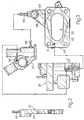
- a spacer plate 57 shown more clearly in Figures 2 and 3 and having a through opening 61 about which is formed, inside plate 57 itself, a duct 62 for the circulation of cooling liquid heated at the output of engine 1.
- the said duct 62 is shaped in the form of a closed polygon communicating with an inlet duct 63 coming out of a projecting portion 64 of plate 57 through an outer tube 65; the latter being connected to a tube 66 coming out of a known type of thermostatic unit 67 on the cooling liquid circuit of engine 1.
- the said thermostatic unit 67 is also provided with a return tube 68 communicating hydraulically with a vertical-axis hole 70 formed on plate 57 and communicating with duct 62, and with duct 62' formed on carburettor 37 for heating the part about the progressive supply holes.
- FIG. 4 shows a block diagram of the extra petrol supply system for starting up engine 1.
- a petrol tank 71 is connected for supplying the carburettor 37 via a pipe 73 having, in series, an electric pump 74, an electrovalve 75 and a known type of one-way valve 76.
- Electric supply to pump 74 and electrovalve 75 is controlled by a timing block 77 controlled by a switch 78, for starting up engine 1, and the operating time of which is controlled by an essentially known type of thermal sensor comprising a twin-metal blade wound with a resistor supplied by the same electric circuit, the said sensor being conveniently arranged in thermal contact with the thermostatic unit 67 in Figure 3.
- pipe 73 comes out inside carburettor 37 through an end tube 80, the inlet of which is fitted with one-way valve 76, and the end of which terminates in a zone 81 inside carburettor 37 and between slow-running jet 82 and main jet 83.
- the supply and control system for a mainly ethanol-powered internal combustion engine 1 operates as follows.
- engine 1 When engine 1 is run normally, the heated cooling liquid comes out of engine 1 through thermostatic unit 67 and, via tubes 66 and 65, is sent to duct 62 on spacer plate 57 from which it is sent back to unit 67 via hole 70, duct 62' and tube 68, thus circulating hot water for heating carburettor 37 and the area around opening 61 through which the fuel mixture flows. Further heat is provided by circulating exhaust gas from exhaust pipe 5 along pipe 21 towards compartment 22.
- the percentage of exhaust gas recirculated into compartment 22 depends on the setting of diaphragm 13, which closes opening 11 to a greater or lesser degree, depending on the vacuum in intake pipe 23, which, via branch 26' of pipe 26 and branch 44, is sent to operating chamber 19 on pneumatic actuator 15.
- throttle 38 on carburettor 37 is practically closed, so that diaphragm 13 closes practically the whole of opening 11 and a maximum amount of exhaust gas is recirculated into compartment 22; and vice versa in the reverse condition wherein throttle 38 is wide open.
- Thermal sensor 55 which, via pipe branch 26", detects the vacuum inside intake pipe 23 and, via electrovalve 52, controls pneumatic actuator 31, operates in such a manner that, with a vacuum of over 90 mm/Hg inside intake pipe 23, diaphragm 32 is set so as to control the temperature of the air mixture supplied to carburettor 37 at around an average of 50°C. With a vacuum of less than 90 mm/Hg inside intake pipe 23, diaphragm 32 is set so as to shut hot-air input pipe 34 off completely and so allow only cold air to be supplied from pipe 33. In such a condition wherein throttle 38 on carburettor 37 is practically wide open (e.g. driving uphill or at maximum vehicle speed), and ambient temperature is relatively low, e.g.
- thermal switch 50 activates circuit block 49 which, in turn, activates electrovalve 52 for connecting one-way valve 54, instead of thermal sensor 55, between operating chamber 19' on actuator 31 and branch 26.
- electrovalve 52 for connecting one-way valve 54, instead of thermal sensor 55, between operating chamber 19' on actuator 31 and branch 26.
- the maximum vacuum formed inside intake pipe 23 is maintained (memorised) inside operating chamber 19' on pneumatic actuator 31, thus ensuring diaphragm 32 is set in such a manner as to allow hot air to be supplied from pipe 34.
- circuit 'block 49 also controls, in addition to electrovalve 52, electrovalve 41 which cuts off direct communication, via branch 44, with chamber 19 on actuator 15 and connects branch 45 with delay valve 46.
- This provides for retarding adjustment of diaphragm 13 in relation to that of throttle 38 on carburettor 37, in such a manner as to ensure an initial period, during acceleration, in which sufficient exhaust gas is forced into compartment 22 for bringing the fuel mixture inside intake pipe 23 up to a suitable temperature for ensuring smooth operation of engine 1.
- temperature switch 48 which, at such a threshold, activates electrovalve 40 which prevents the vacuum in intake pipe 23 from being sent to operating chamber 19 on actuator 15, and connects it to the outside atmospheric pressure via filter 42.
- the effect of this is to cause diaphragm 13 to open completely, thus reducing drastically the amount of heat transferred to the fuel mixture by the exhaust gas.
- the fuel mixture when starting up engine 1, particularly at temperatures below 20°C, the fuel mixture must consist of ethanol and petrol, preferably 80% of the former and 20% of the latter.
- the supply system according to the present invention ( Figure 5) provides for feeding petrol in smaller amounts and to a point far more effective in terms of start-up performance, i.e. via tube 80, petrol is fed to point 81 halfway between slow-running jet 82 and main jet 83.
- Supplying the required amount of petrol is enabled by timing block 77 ( Figure 4), which, via the temperature sensor already mentioned, controls power supply to pump 74 and electrovalve 75.
- Block 77 and, consequently, pump 74 and electrovalve 75 are supplied initially, by operating starting switch 78, from when engine 1 is started up by the starting motor, until power is cut off by the temperature sensor, which also detects the temperature of the cooling liquid.
- the operating time of timing block 77 therefore depends on the initial temperature of thermostatic unit 67, i.e. the higher the temperature, the shorter the operating time of block 77.
- the supply and control system for a mainly ethanol-powered internal combustion engine according to the present invention obviously provides for a number of advantages permitting essentially smooth, reliable operation of engine 1 under various operating conditions.
Landscapes
- Engineering & Computer Science (AREA)
- Chemical & Material Sciences (AREA)
- Combustion & Propulsion (AREA)
- Mechanical Engineering (AREA)
- General Engineering & Computer Science (AREA)
- Output Control And Ontrol Of Special Type Engine (AREA)
Claims (7)
Applications Claiming Priority (2)
| Application Number | Priority Date | Filing Date | Title |
|---|---|---|---|
| IT6827584 | 1984-12-21 | ||
| IT68275/84A IT1179888B (it) | 1984-12-21 | 1984-12-21 | Sistema di alimentazione e controllo per un motore endotermico funzionante principalmente ad etanolo |
Publications (3)
| Publication Number | Publication Date |
|---|---|
| EP0187280A2 EP0187280A2 (de) | 1986-07-16 |
| EP0187280A3 EP0187280A3 (en) | 1987-06-16 |
| EP0187280B1 true EP0187280B1 (de) | 1989-07-05 |
Family
ID=11308795
Family Applications (1)
| Application Number | Title | Priority Date | Filing Date |
|---|---|---|---|
| EP85115614A Expired EP0187280B1 (de) | 1984-12-21 | 1985-12-09 | Versorgungs- und Regeleinrichtung für eine hauptsächlich mit Äthylalkohol betriebene Brennkraftmaschine |
Country Status (5)
| Country | Link |
|---|---|
| EP (1) | EP0187280B1 (de) |
| BR (1) | BR8501218A (de) |
| DE (1) | DE3571336D1 (de) |
| ES (1) | ES8700390A1 (de) |
| IT (1) | IT1179888B (de) |
Families Citing this family (1)
| Publication number | Priority date | Publication date | Assignee | Title |
|---|---|---|---|---|
| WO1990000226A1 (en) * | 1988-07-01 | 1990-01-11 | Robert Bosch Gmbh | Motor fuel supply system |
Family Cites Families (6)
| Publication number | Priority date | Publication date | Assignee | Title |
|---|---|---|---|---|
| US3714933A (en) * | 1970-11-16 | 1973-02-06 | Honda Motor Co Ltd | Automatic temperature control device for intake air of an internal combustion engine |
| DE2257866A1 (de) * | 1971-11-30 | 1973-06-07 | Toyo Kogyo Co | Kaltstartvorrichtung fuer innere brennkraftmaschinen |
| US4079715A (en) * | 1973-01-29 | 1978-03-21 | Nissan Motor Company, Ltd. | Warming-up system for internal combustion engines |
| US4161930A (en) * | 1978-02-14 | 1979-07-24 | Filterwerk Mann & Hummel Gmbh | Device for regulating the intake air temperature of a carburetor-equipped internal combustion engine |
| DE3036271A1 (de) * | 1980-09-26 | 1982-05-19 | Pierburg Gmbh & Co Kg, 4040 Neuss | Regeleinrichtung fuer die ansuggemischtemperatur einer gemischverdichtenden brennkraftmaschine |
| US4441467A (en) * | 1982-07-23 | 1984-04-10 | General Motors Corporation | Supplementary fuel system for enhancing low temperature engine operation |
-
1984
- 1984-12-21 IT IT68275/84A patent/IT1179888B/it active
-
1985
- 1985-03-19 BR BR8501218A patent/BR8501218A/pt not_active IP Right Cessation
- 1985-12-09 DE DE8585115614T patent/DE3571336D1/de not_active Expired
- 1985-12-09 EP EP85115614A patent/EP0187280B1/de not_active Expired
- 1985-12-20 ES ES550213A patent/ES8700390A1/es not_active Expired
Also Published As
| Publication number | Publication date |
|---|---|
| DE3571336D1 (en) | 1989-08-10 |
| IT1179888B (it) | 1987-09-16 |
| EP0187280A3 (en) | 1987-06-16 |
| EP0187280A2 (de) | 1986-07-16 |
| ES8700390A1 (es) | 1986-10-16 |
| IT8468275A0 (it) | 1984-12-21 |
| ES550213A0 (es) | 1986-10-16 |
| BR8501218A (pt) | 1986-10-07 |
Similar Documents
| Publication | Publication Date | Title |
|---|---|---|
| US4068639A (en) | Automobile engine economizer | |
| US3646924A (en) | Fuel system for gaseous fueled engines | |
| US4625910A (en) | Heater system associated with engine | |
| US4079715A (en) | Warming-up system for internal combustion engines | |
| US4836445A (en) | Vehicle heating system | |
| FI71092B (fi) | Uppvaermningsanordning foer manoevreringskabinen av en anordning speciellt ett fordon | |
| US4394960A (en) | Heating apparatus for a passenger compartment of a motor vehicle | |
| US5250268A (en) | Catalytic cleaning arrangement for exhaust from an internal combustion engine | |
| US3963013A (en) | Air and fuel charge forming device | |
| US4005693A (en) | Warming-up system for internal combustion engines | |
| GB2099573A (en) | Engine cooling systems | |
| US4053544A (en) | Fuel induction system for internal combustion engines | |
| US3789812A (en) | Air/fuel mixing system controlled by temperature activated mechanism for internal combustion engines | |
| US3913544A (en) | Induction air temperature control apparatus for an internal combustion engine | |
| US4346686A (en) | Idle controller for an internal combustion engine | |
| EP0187280B1 (de) | Versorgungs- und Regeleinrichtung für eine hauptsächlich mit Äthylalkohol betriebene Brennkraftmaschine | |
| US3835903A (en) | Apparatus for warming cooling and/or lubricating media of internal combustion engines | |
| US4925091A (en) | Vehicle engine warming and passenger compartment heating device | |
| GB2043785A (en) | Carburettor unit for a multicylinder internal combustion engine | |
| US4075837A (en) | Exhaust gas purifying system for an internal combustion engine | |
| US5385132A (en) | Engine fluid system | |
| US4442811A (en) | Method and apparatus for expediting the starting of an internal combustion engine | |
| US4527519A (en) | Method and system for controlling intake flow between direct and helical intake passages of intake port of internal combustion engine | |
| JP2002097952A (ja) | 車両用排気マニホールド装置 | |
| JPS5974345A (ja) | エンジンの気筒数制御装置 |
Legal Events
| Date | Code | Title | Description |
|---|---|---|---|
| PUAI | Public reference made under article 153(3) epc to a published international application that has entered the european phase |
Free format text: ORIGINAL CODE: 0009012 |
|
| AK | Designated contracting states |
Kind code of ref document: A2 Designated state(s): DE FR GB SE |
|
| PUAL | Search report despatched |
Free format text: ORIGINAL CODE: 0009013 |
|
| AK | Designated contracting states |
Kind code of ref document: A3 Designated state(s): DE FR GB SE |
|
| 17P | Request for examination filed |
Effective date: 19870922 |
|
| 17Q | First examination report despatched |
Effective date: 19880426 |
|
| GRAA | (expected) grant |
Free format text: ORIGINAL CODE: 0009210 |
|
| AK | Designated contracting states |
Kind code of ref document: B1 Designated state(s): DE FR GB SE |
|
| REF | Corresponds to: |
Ref document number: 3571336 Country of ref document: DE Date of ref document: 19890810 |
|
| ET | Fr: translation filed | ||
| PLBE | No opposition filed within time limit |
Free format text: ORIGINAL CODE: 0009261 |
|
| STAA | Information on the status of an ep patent application or granted ep patent |
Free format text: STATUS: NO OPPOSITION FILED WITHIN TIME LIMIT |
|
| 26N | No opposition filed | ||
| PGFP | Annual fee paid to national office [announced via postgrant information from national office to epo] |
Ref country code: SE Payment date: 19931108 Year of fee payment: 9 |
|
| PGFP | Annual fee paid to national office [announced via postgrant information from national office to epo] |
Ref country code: GB Payment date: 19931202 Year of fee payment: 9 |
|
| PG25 | Lapsed in a contracting state [announced via postgrant information from national office to epo] |
Ref country code: GB Effective date: 19941209 |
|
| PG25 | Lapsed in a contracting state [announced via postgrant information from national office to epo] |
Ref country code: SE Effective date: 19941210 |
|
| PGFP | Annual fee paid to national office [announced via postgrant information from national office to epo] |
Ref country code: FR Payment date: 19941215 Year of fee payment: 10 |
|
| PGFP | Annual fee paid to national office [announced via postgrant information from national office to epo] |
Ref country code: DE Payment date: 19950124 Year of fee payment: 10 |
|
| EAL | Se: european patent in force in sweden |
Ref document number: 85115614.1 |
|
| GBPC | Gb: european patent ceased through non-payment of renewal fee |
Effective date: 19941209 |
|
| EUG | Se: european patent has lapsed |
Ref document number: 85115614.1 |
|
| PG25 | Lapsed in a contracting state [announced via postgrant information from national office to epo] |
Ref country code: FR Effective date: 19960830 |
|
| PG25 | Lapsed in a contracting state [announced via postgrant information from national office to epo] |
Ref country code: DE Effective date: 19960903 |
|
| REG | Reference to a national code |
Ref country code: FR Ref legal event code: ST |