EP0187302A2 - Slide fastener with a pair of intermeshable top end stops - Google Patents
Slide fastener with a pair of intermeshable top end stops Download PDFInfo
- Publication number
- EP0187302A2 EP0187302A2 EP85115854A EP85115854A EP0187302A2 EP 0187302 A2 EP0187302 A2 EP 0187302A2 EP 85115854 A EP85115854 A EP 85115854A EP 85115854 A EP85115854 A EP 85115854A EP 0187302 A2 EP0187302 A2 EP 0187302A2
- Authority
- EP
- European Patent Office
- Prior art keywords
- top end
- slider
- pair
- end stops
- slide fastener
- Prior art date
- Legal status (The legal status is an assumption and is not a legal conclusion. Google has not performed a legal analysis and makes no representation as to the accuracy of the status listed.)
- Granted
Links
Images

Classifications
-
- A—HUMAN NECESSITIES
- A44—HABERDASHERY; JEWELLERY
- A44B—BUTTONS, PINS, BUCKLES, SLIDE FASTENERS, OR THE LIKE
- A44B19/00—Slide fasteners
-
- A—HUMAN NECESSITIES
- A44—HABERDASHERY; JEWELLERY
- A44B—BUTTONS, PINS, BUCKLES, SLIDE FASTENERS, OR THE LIKE
- A44B19/00—Slide fasteners
- A44B19/24—Details
- A44B19/36—Means for permanently uniting the stringers at the end; Means for stopping movement of slider at the end
-
- Y—GENERAL TAGGING OF NEW TECHNOLOGICAL DEVELOPMENTS; GENERAL TAGGING OF CROSS-SECTIONAL TECHNOLOGIES SPANNING OVER SEVERAL SECTIONS OF THE IPC; TECHNICAL SUBJECTS COVERED BY FORMER USPC CROSS-REFERENCE ART COLLECTIONS [XRACs] AND DIGESTS
- Y10—TECHNICAL SUBJECTS COVERED BY FORMER USPC
- Y10T—TECHNICAL SUBJECTS COVERED BY FORMER US CLASSIFICATION
- Y10T24/00—Buckles, buttons, clasps, etc.
- Y10T24/25—Zipper or required component thereof
- Y10T24/2561—Slider having specific configuration, construction, adaptation, or material
- Y10T24/2566—Slider having specific configuration, construction, adaptation, or material including position locking-means attached thereto
- Y10T24/2568—Protrusion on pull tab directly engaging interlocking surfaces
-
- Y—GENERAL TAGGING OF NEW TECHNOLOGICAL DEVELOPMENTS; GENERAL TAGGING OF CROSS-SECTIONAL TECHNOLOGIES SPANNING OVER SEVERAL SECTIONS OF THE IPC; TECHNICAL SUBJECTS COVERED BY FORMER USPC CROSS-REFERENCE ART COLLECTIONS [XRACs] AND DIGESTS
- Y10—TECHNICAL SUBJECTS COVERED BY FORMER USPC
- Y10T—TECHNICAL SUBJECTS COVERED BY FORMER US CLASSIFICATION
- Y10T24/00—Buckles, buttons, clasps, etc.
- Y10T24/25—Zipper or required component thereof
- Y10T24/2561—Slider having specific configuration, construction, adaptation, or material
- Y10T24/2586—Slider having specific configuration, construction, adaptation, or material including pull tab attaching means
-
- Y—GENERAL TAGGING OF NEW TECHNOLOGICAL DEVELOPMENTS; GENERAL TAGGING OF CROSS-SECTIONAL TECHNOLOGIES SPANNING OVER SEVERAL SECTIONS OF THE IPC; TECHNICAL SUBJECTS COVERED BY FORMER USPC CROSS-REFERENCE ART COLLECTIONS [XRACs] AND DIGESTS
- Y10—TECHNICAL SUBJECTS COVERED BY FORMER USPC
- Y10T—TECHNICAL SUBJECTS COVERED BY FORMER US CLASSIFICATION
- Y10T24/00—Buckles, buttons, clasps, etc.
- Y10T24/25—Zipper or required component thereof
- Y10T24/2598—Zipper or required component thereof including means for obstructing movement of slider
-
- Y—GENERAL TAGGING OF NEW TECHNOLOGICAL DEVELOPMENTS; GENERAL TAGGING OF CROSS-SECTIONAL TECHNOLOGIES SPANNING OVER SEVERAL SECTIONS OF THE IPC; TECHNICAL SUBJECTS COVERED BY FORMER USPC CROSS-REFERENCE ART COLLECTIONS [XRACs] AND DIGESTS
- Y10—TECHNICAL SUBJECTS COVERED BY FORMER USPC
- Y10T—TECHNICAL SUBJECTS COVERED BY FORMER US CLASSIFICATION
- Y10T24/00—Buckles, buttons, clasps, etc.
- Y10T24/26—Slit closing means including guides on opposite edges of slit and slidable bridging component
Definitions
- the present invention relates to the production of slide fasteners, and more particularly to a slide fastener having a pair of intermeshable top end stops.
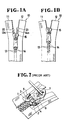
- top stop assemblies as disclosed in Japanese Utility Model Post-Examination Publication (Jikkosho) 46-6577 and reillustrated in Figure 7 of the accompanying drawings, comprises a pair of top end stops 1, 2 each having a guide recess 3, 4 extending from its upper end and terminating short of its lower end. Both the width and the depth of the recess 3, 4 decrease gradually from the upper end to the lower end of the individual top end stop 1, 2.
- This recess 3, 4 thus serves as a one-way path for one of opposite side flanges 5, 6 of a slider 7; the two top end stops 1, 2 resiliently deform when the side flanges 5, 6 of the slider 7 are forced past these top end stops 1, 2 during the threading.
- a slide fastener comprising: a pair of stringer tapes; a pair of rows of fastener elements mounted on said stringer tapes along respective inner longitudinal edges thereof; a slider threaded onto said pair of rows of fastener elements for movement therealong to close and open the slide fastener, said slider including a slider body having a neck portion disposed centrally at a flared front end thereof and a pair of first and second flaring flanges disposed along opposite sides of said slider so as to define with said neck portion a Y-shaped guide channel for passage of said pair of rows of fastener elements; a bottom stop mounted on said inner longitudinal edges of said stringer tapes adjacent to the lowermost fastener element for limiting backward movement of said slider; and a top stop assembly for limiting forward movement of said slider said assembly including a first top end stop mounted on said inner longitudinal edge of one of said stringer tapes adjacent to the uppermost fastener element, and a second top end stop mounted on said inner longitudinal edge of the other
- the present invention seeks tp provide a slide fastener having a pair of top end stops which are intermeshable so that a slider can be threaded onto a pair of fastener stringers easily without any deformation of either the top end stops or the slider.
- the present invention further seeks to provide a slide fastener having a pair of top end stops which can enter a slider thoroughly when the latter is pulled all the way upwardly or forwardly to close the slide fastener, thus making the slide fastener neat in appearance.
- the present invention is particularly useful when embodied in a slide fastener such as shown in Figure 1A, generally indicated by the numeral 10.
- the slide fastener 10 generally comprises a pair of fastener stringers including a pair of stringer tapes 11, 12 and a pair of fastener stringers for movement along the pair of rows of fastener elements 13, 14 mounted on the stringer tapes 11, 12 along their respective inner longitudinal edges, and a slider 15 threaded onto the pair of fastener stringers for movement along the pair of rows of fastener elements 13, 14 to close and open the slide fastener 10.
- a bottom end stop (not shown) is mounted on the pair of stringers at the lower end of the fastener element rows 13, 14 for limiting backward or downward movement of the slider 15.
- a top stop assembly which is described below in detail, is mounted for limiting forward or upward movement of the slider 15.
- the slider 15 includes a slider body having a wedge-shaped neck portion 17 disposed centrally at a flared front end 18 thereof and a pair of first and second flaring flanges 19, 20 disposed along opposite slides of the slider 15 to define with the neck portion 17 a Y-shaped guide channel 21 for passage of the top stop assembly (as described below) as well as the fastener element rows 13, 14.
- the top stop assembly includes a first top end stop 22 mounted on the inner longitudinal edge of one of the fastener tapes 11 adjacent to the uppermost fastener element 13a, and a second top end stop 23 mounted on the inner longitudinal edge of the other fastener tape 12 adjacent to the upper most fastener element 14a and meshable with the first top end stop 22 so as to make the total width D (Figure 5A) of the top stop assembly slightly smaller than the minimum width d of the guide channel 21 for allowing the top stop assembly to pass therethrough without any deformation of either the slider 15 or these top end stops 23, 23 during the threading.
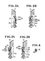
- the first and second top end stops 22, 23 have at their inner sides a pair of mating stepped portions 24, 25 complementary in shape to each other, each stepped portion 24, 25 defining a projection 24a, 25a and a recess 24b, 25b which is receptive of each other's projection 25a. 24a, as shown in Figure 5A.
- the top stop assembly also includes a blocking means for being attached to one of the mating stepped portions 24, 25 to close the corresponding recess 24b, 25b, thus preventing the first and second top end stops 22, 23 from meshing with each other.
- the blocking means is in the form of a piece of rigid and solid material 26 having a tongue 26a
- the stepped portion 24, 25 of each top end stop 22, 23 has a hole 24c, 25c for receiving the tongue 26a when the blocking piece 26 is attached to the stepped portion 24, 25.
- the tongue 26a and the corresponding hole 24c, 25c jointly serve to assist in placing the blocking piece 26 in correct position at the stepped portion 24, 25.
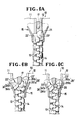
- Each top end stop 23, 23 has a width W (Figure 5B) smaller than the minimum distance w between the neck portion 17 and the corresponding flaring side flange 19, 20 of the slider 15 so that the two top end stops 22, 23, even with the blocking piece 26 attached to one of them, can enter the slider 15 thoroughly (Figure 5C) when the latter is pulled all the way to close the slide fastener 10, thus making the slide fastener 10 neat in appearance, as shown in Figure 1B.
- the pair of fastener stringers of Figures 2A and 2B are coupled to togetherer, at which time the first and second top and stops 22, 23 as well as the pair of fastener element rows 13, 14 are intermeshed respectively.
- the thus coupled fastener stringers are then threaded through the slider 15 from their top end, as shown in Figures 5A and 5B. until the slider 15 is moved past the top end stops 22, 23 as shown in Figure 1 A.
- the blocking piece 26 is attached to the stepped portion 24 of the second top end stop 23 to thereby prevent the latter from meshing with the first top end stop 22.
- the two top end stops 22, 23 can no longer pass through the narrow end of the Y-shaped guide channel 21 of the slider 15, as shown in Figure 5C, when the latter is pulled all the way upwardly or forwardly to close the slide fastener 10, but these two top end stops 22, 23 can only enter the slider 15 thoroughly and then cannot be observed from outside.
- Figures 6A, 6B and 6C illustrate a second embodiment in which the first and second top end stops 22', 23' have a pair of modified mating stepped portions 24', 25'.
- the first top end stop 22' has at its upper inner portion a recess 24b' receptive of a projection 25a' extending from the corresponding portion of the second top end stop 23', while the second top end stop 23' has at its lower inner portion a recess 25b' receptive of a projection 24a' extending from the corresponding portion of the first top end stop 22'.
- these two top end stops 22', 23' can mesh with each other so as to become shrunk in total width so that the slider 15 can be moved past the two top end stops 22', 23' without any deformation of either the slider 15 or the top end stops 22', 23' during the threading, as shown in Figures 6A and 6B.
- a blocking piece 26 of rigid and solid material is attached, by bonding for example, to the stepped portion 25' of at least one of the two top end stops 22' after the threading, the two top end stops 22', 23' are then prevented from meshing with each other and hence can no longer pass through the narrow end of the Y-shaped guide channel 21 of the slider 15. And these two top end stops 22', 23' can enter the slider 15 entirely when the latter is pulled all the way upwardly or forwardly to close the slide fastener 10, as shown in Figure 6C.
Landscapes
- Slide Fasteners (AREA)
Abstract
Description
- The present invention relates to the production of slide fasteners, and more particularly to a slide fastener having a pair of intermeshable top end stops.
- In the manufacture of slide fasteners, it has been a known practice to thread individual sliders one after another onto a continuous slide fastener chain to which a plurality of pairs of top end stops and a plurality of bottom end stops (or separable bottom stop assemblies) have been attached beforehand. To this end, various types of top stop assemblies have been proposed which allow a slider to be moved past the top end stops during the threading and which then prevent the slider from being moved past the same top end stops after the threading.
- One example of such top stop assemblies, as disclosed in Japanese Utility Model Post-Examination Publication (Jikkosho) 46-6577 and reillustrated in Figure 7 of the accompanying drawings, comprises a pair of top end stops 1, 2 each having a
guide recess 3, 4 extending from its upper end and terminating short of its lower end. Both the width and the depth of therecess 3, 4 decrease gradually from the upper end to the lower end of the individual top end stop 1, 2. Thisrecess 3, 4 thus serves as a one-way path for one ofopposite side flanges - According to the present invention, there is provided a slide fastener comprising: a pair of stringer tapes; a pair of rows of fastener elements mounted on said stringer tapes along respective inner longitudinal edges thereof; a slider threaded onto said pair of rows of fastener elements for movement therealong to close and open the slide fastener, said slider including a slider body having a neck portion disposed centrally at a flared front end thereof and a pair of first and second flaring flanges disposed along opposite sides of said slider so as to define with said neck portion a Y-shaped guide channel for passage of said pair of rows of fastener elements; a bottom stop mounted on said inner longitudinal edges of said stringer tapes adjacent to the lowermost fastener element for limiting backward movement of said slider; and a top stop assembly for limiting forward movement of said slider said assembly including a first top end stop mounted on said inner longitudinal edge of one of said stringer tapes adjacent to the uppermost fastener element, and a second top end stop mounted on said inner longitudinal edge of the other stringer tape adjacent to the uppermost fastener element; CHARACTERIZED IN THAT said second top end stop is meshable with said first top end stop so as to make the total width of said top stop assembly slightly smaller than the minimum width of said guide channel of said slider for allowing said top stop assembly to pass through said guide channel, and THAT said top stop assembly further includes blocking means for being mounted on at least one of said first and second top end stops for preventing said first and second top end stops from meshing with each other.
- The present invention seeks tp provide a slide fastener having a pair of top end stops which are intermeshable so that a slider can be threaded onto a pair of fastener stringers easily without any deformation of either the top end stops or the slider.
- The present invention further seeks to provide a slide fastener having a pair of top end stops which can enter a slider thoroughly when the latter is pulled all the way upwardly or forwardly to close the slide fastener, thus making the slide fastener neat in appearance.
- Many other objects, advantages and additional features of the present invention will become manifest to those versed in the art upon making reference to the detailed description and the accompanying sheets of drawings in which two preferred structural embodiments incorporating the principles of the present invention are shown by way of illustrative example.
-
- Figure 1 A is a fragmentary plan view of a slide fastener having a pair of mating top end stops embodying the present invention;
- Figure 1 B is a view similar to Figure 1 A, showing the slide fastener having been fully closed;
- Figure 2A is an enlarged, fragmentary perspective view of Figure 1A, showing one fastener stringer on which one of the mating top end stops is mounted;
- Figure 2B is a view similar to Figure 2A, showing the other fastener stringer on which the other top end stop is mounted;
- Figures 3A and 3B illustrate the manner in which a blocking piece is attached to one of the mating top end stops;
- Figure 4 is a perspective view of the blocking piece of Figure 3B;
- Figures 5A, 5B and 5C are fragmentary plan views, par- tally in cross section, illustrating the mode of operation of the mating top end stops;
- Figures 6A, 6B and 6C are view similar to Figures 5A, 5B and 5C, illustrating a modification of the mating top end stops; and
- Figure 7, appearing with Figures 1A and 1B, is a fragmentary perspective view of a prior art slide fastener.
- The present invention is particularly useful when embodied in a slide fastener such as shown in Figure 1A, generally indicated by the
numeral 10. - The
slide fastener 10 generally comprises a pair of fastener stringers including a pair ofstringer tapes fastener elements stringer tapes slider 15 threaded onto the pair of fastener stringers for movement along the pair of rows offastener elements slide fastener 10. A bottom end stop (not shown) is mounted on the pair of stringers at the lower end of thefastener element rows slider 15. At the upper end of the fastenere.ement rows slider 15. - As shown in Figures 5A-5C and 6A-6C, the
slider 15 includes a slider body having a wedge-shaped neck portion 17 disposed centrally at aflared front end 18 thereof and a pair of first andsecond flaring flanges slider 15 to define with the neck portion 17 a Y-shaped guide channel 21 for passage of the top stop assembly (as described below) as well as thefastener element rows - The top stop assembly, as better shown in Figures 1A, 2A and 2B, includes a first
top end stop 22 mounted on the inner longitudinal edge of one of thefastener tapes 11 adjacent to theuppermost fastener element 13a, and a secondtop end stop 23 mounted on the inner longitudinal edge of theother fastener tape 12 adjacent to the uppermost fastener element 14a and meshable with the firsttop end stop 22 so as to make the total width D (Figure 5A) of the top stop assembly slightly smaller than the minimum width d of theguide channel 21 for allowing the top stop assembly to pass therethrough without any deformation of either theslider 15 or these top end stops 23, 23 during the threading. - The first and second top end stops 22, 23 have at their inner sides a pair of mating stepped
portions portion projection recess projection 25a. 24a, as shown in Figure 5A. - The top stop assembly also includes a blocking means for being attached to one of the mating stepped
portions corresponding recess solid material 26 having atongue 26a Thestepped portion top end stop hole 24c, 25c for receiving thetongue 26a when the blockingpiece 26 is attached to thestepped portion blocking piece 26, thetongue 26a and thecorresponding hole 24c, 25c jointly serve to assist in placing the blockingpiece 26 in correct position at thestepped portion - Each
top end stop flaring side flange slider 15 so that the two top end stops 22, 23, even with theblocking piece 26 attached to one of them, can enter theslider 15 thoroughly (Figure 5C) when the latter is pulled all the way to close theslide fastener 10, thus making the slide fastener 10 neat in appearance, as shown in Figure 1B. - In assembly, the pair of fastener stringers of Figures 2A and 2B are coupled togehter, at which time the first and second top and stops 22, 23 as well as the pair of
fastener element rows slider 15 from their top end, as shown in Figures 5A and 5B. until theslider 15 is moved past the top end stops 22, 23 as shown in Figure 1 A. Finally, theblocking piece 26 is attached to thestepped portion 24 of the secondtop end stop 23 to thereby prevent the latter from meshing with the firsttop end stop 22. As a result, the two top end stops 22, 23 can no longer pass through the narrow end of the Y-shaped guide channel 21 of theslider 15, as shown in Figure 5C, when the latter is pulled all the way upwardly or forwardly to close theslide fastener 10, but these two top end stops 22, 23 can only enter theslider 15 thoroughly and then cannot be observed from outside. - Figures 6A, 6B and 6C illustrate a second embodiment in which the first and second top end stops 22', 23' have a pair of modified mating stepped portions 24', 25'. The first top end stop 22' has at its upper inner portion a
recess 24b' receptive of aprojection 25a' extending from the corresponding portion of the second top end stop 23', while the second top end stop 23' has at its lower inner portion arecess 25b' receptive of aprojection 24a' extending from the corresponding portion of the first top end stop 22'. Thus these two top end stops 22', 23' can mesh with each other so as to become shrunk in total width so that theslider 15 can be moved past the two top end stops 22', 23' without any deformation of either theslider 15 or the top end stops 22', 23' during the threading, as shown in Figures 6A and 6B. If a blockingpiece 26 of rigid and solid material is attached, by bonding for example, to the stepped portion 25' of at least one of the two top end stops 22' after the threading, the two top end stops 22', 23' are then prevented from meshing with each other and hence can no longer pass through the narrow end of the Y-shaped guide channel 21 of theslider 15. And these two top end stops 22', 23' can enter theslider 15 entirely when the latter is pulled all the way upwardly or forwardly to close theslide fastener 10, as shown in Figure 6C.
Claims (5)
Applications Claiming Priority (2)
| Application Number | Priority Date | Filing Date | Title |
|---|---|---|---|
| JP190461/84 | 1984-12-15 | ||
| JP1984190461U JPH0111060Y2 (en) | 1984-12-15 | 1984-12-15 |
Publications (3)
| Publication Number | Publication Date |
|---|---|
| EP0187302A2 true EP0187302A2 (en) | 1986-07-16 |
| EP0187302A3 EP0187302A3 (en) | 1987-09-02 |
| EP0187302B1 EP0187302B1 (en) | 1989-11-02 |
Family
ID=16258498
Family Applications (1)
| Application Number | Title | Priority Date | Filing Date |
|---|---|---|---|
| EP85115854A Expired EP0187302B1 (en) | 1984-12-15 | 1985-12-12 | Slide fastener with a pair of intermeshable top end stops |
Country Status (13)
| Country | Link |
|---|---|
| US (1) | US4667377A (en) |
| EP (1) | EP0187302B1 (en) |
| JP (1) | JPH0111060Y2 (en) |
| KR (1) | KR870002381Y1 (en) |
| AU (1) | AU559982B2 (en) |
| BR (1) | BR8506530A (en) |
| CA (1) | CA1277483C (en) |
| DE (1) | DE3573979D1 (en) |
| ES (1) | ES296401Y (en) |
| GB (1) | GB2168425B (en) |
| HK (1) | HK61290A (en) |
| MY (1) | MY100963A (en) |
| SG (1) | SG56390G (en) |
Cited By (1)
| Publication number | Priority date | Publication date | Assignee | Title |
|---|---|---|---|---|
| EP0287972A1 (en) * | 1987-04-20 | 1988-10-26 | Yoshida Kogyo K.K. | Separable bottom end stop for slide fastener |
Families Citing this family (7)
| Publication number | Priority date | Publication date | Assignee | Title |
|---|---|---|---|---|
| US6701585B2 (en) * | 2002-07-31 | 2004-03-09 | Chang-Wen Tsaur | Stop device for upper stops and a pull of a nylon zipper |
| JP3952462B2 (en) * | 2002-12-20 | 2007-08-01 | Ykk株式会社 | Hidden slide fastener |
| US20050060848A1 (en) * | 2003-09-22 | 2005-03-24 | Chang-Wen Tsaur | Upper stopper structure of zipper |
| GB0506680D0 (en) * | 2005-04-01 | 2005-05-11 | Ykk Europ Ltd | A readily burstable slide fastener |
| JP4238229B2 (en) * | 2005-04-20 | 2009-03-18 | Ykk株式会社 | Top stopper for slide fastener |
| GB2464766A (en) | 2008-10-30 | 2010-05-05 | Ykk Europ Ltd | Locking stop having split projection |
| WO2014167654A1 (en) * | 2013-04-09 | 2014-10-16 | Ykk株式会社 | Slide fastener and method for use thereof |
Family Cites Families (12)
| Publication number | Priority date | Publication date | Assignee | Title |
|---|---|---|---|---|
| US1910953A (en) * | 1931-07-29 | 1933-05-23 | United Carr Fastener Corp | Stop for multiple operated fastener closures |
| US1910404A (en) * | 1932-01-06 | 1933-05-23 | Prentice G E Mfg Co | Slider locking stop |
| US1952506A (en) * | 1933-04-15 | 1934-03-27 | Prentice G E Mfg Co | Stop for fasteners |
| US2422091A (en) * | 1944-09-02 | 1947-06-10 | Talon Inc | Top stop for slide fasteners |
| US2599165A (en) * | 1946-03-13 | 1952-06-03 | Bolta Company | Molded stop mechanism for sliding clasp fasteners |
| US2601710A (en) * | 1948-06-26 | 1952-07-01 | Conmar Prod Corp | Slide fastener with releasing top stop |
| GB706794A (en) * | 1951-07-25 | 1954-04-07 | Aero Zipp Fasteners Ltd | Improvements in or relating to slide fasteners |
| US2977638A (en) * | 1955-09-09 | 1961-04-04 | Louis H Morin | Integral end stop for separable fasteners and the method of producing the same |
| JPS5328573Y2 (en) * | 1972-07-18 | 1978-07-18 | ||
| JPS5175886A (en) * | 1974-12-28 | 1976-06-30 | Fuji Electric Co Ltd | Ondochosetsukino dejitarusetsuteikairo |
| JPS5637608Y2 (en) * | 1975-12-29 | 1981-09-03 | ||
| JPS5740805Y2 (en) * | 1978-02-21 | 1982-09-08 |
-
1984
- 1984-12-15 JP JP1984190461U patent/JPH0111060Y2/ja not_active Expired
-
1985
- 1985-12-03 AU AU50710/85A patent/AU559982B2/en not_active Ceased
- 1985-12-03 GB GB08529730A patent/GB2168425B/en not_active Expired
- 1985-12-09 CA CA000497166A patent/CA1277483C/en not_active Expired - Lifetime
- 1985-12-12 EP EP85115854A patent/EP0187302B1/en not_active Expired
- 1985-12-12 DE DE8585115854T patent/DE3573979D1/en not_active Expired
- 1985-12-13 BR BR8506530A patent/BR8506530A/en not_active IP Right Cessation
- 1985-12-13 KR KR2019850016732U patent/KR870002381Y1/en not_active Expired
- 1985-12-13 US US06/808,484 patent/US4667377A/en not_active Expired - Fee Related
- 1985-12-13 ES ES1985296401U patent/ES296401Y/en not_active Expired
-
1987
- 1987-08-18 MY MYPI87001364A patent/MY100963A/en unknown
-
1990
- 1990-07-17 SG SG563/90A patent/SG56390G/en unknown
- 1990-08-09 HK HK612/90A patent/HK61290A/en not_active IP Right Cessation
Cited By (2)
| Publication number | Priority date | Publication date | Assignee | Title |
|---|---|---|---|---|
| EP0287972A1 (en) * | 1987-04-20 | 1988-10-26 | Yoshida Kogyo K.K. | Separable bottom end stop for slide fastener |
| US4858284A (en) * | 1987-04-20 | 1989-08-22 | Yoshida Kogyo K. K. | Separable bottom end stop for slide fastener |
Also Published As
| Publication number | Publication date |
|---|---|
| BR8506530A (en) | 1986-09-09 |
| MY100963A (en) | 1991-06-15 |
| KR860007111U (en) | 1986-07-10 |
| DE3573979D1 (en) | 1989-12-07 |
| AU559982B2 (en) | 1987-03-26 |
| ES296401Y (en) | 1988-03-16 |
| CA1277483C (en) | 1990-12-11 |
| EP0187302B1 (en) | 1989-11-02 |
| AU5071085A (en) | 1986-06-19 |
| US4667377A (en) | 1987-05-26 |
| GB8529730D0 (en) | 1986-01-08 |
| JPS61105010U (en) | 1986-07-03 |
| HK61290A (en) | 1990-08-17 |
| JPH0111060Y2 (en) | 1989-03-30 |
| ES296401U (en) | 1987-08-16 |
| EP0187302A3 (en) | 1987-09-02 |
| KR870002381Y1 (en) | 1987-07-16 |
| GB2168425B (en) | 1988-09-01 |
| GB2168425A (en) | 1986-06-18 |
| SG56390G (en) | 1990-09-07 |
Similar Documents
| Publication | Publication Date | Title |
|---|---|---|
| EP0097362B1 (en) | Slide fastener slider | |
| US4742603A (en) | Separable bottom-end-stop assembly for separable slide fastener | |
| EP0124867B1 (en) | Slider for slide fasteners | |
| US4658480A (en) | Fluid-tight slide fastener | |
| US4409705A (en) | Slider for a slide fastener | |
| EP0178585B1 (en) | Slide fastener slider with detachable pull tab | |
| US3872551A (en) | Slide fastener having separating end stop | |
| US3663996A (en) | Tape-supported separable slide fastener | |
| US4942648A (en) | Separable type water-resistant slide fasteners | |
| EP0187302B1 (en) | Slide fastener with a pair of intermeshable top end stops | |
| EP0069337B1 (en) | Slider for slide fastener | |
| US4651388A (en) | Sliding clasp fastener | |
| EP0595248A1 (en) | Separable bottom stop for concealed type slide fastener | |
| EP0387368B1 (en) | Separable slide fastener | |
| US4490889A (en) | Slide fastener assembly | |
| US4441235A (en) | Slide fastener with bottom stop | |
| EP0051219A1 (en) | Slide fastener with separable bottom end stop | |
| EP0287972B1 (en) | Separable bottom end stop for slide fastener | |
| GB1467526A (en) | Top stops for sliding clasp fasteners | |
| US4510655A (en) | Slide fastener assembly for case or folder | |
| US4660258A (en) | Separable slide fastener | |
| EP0041237A1 (en) | Bridge top stop for slide fasteners | |
| EP0095161B1 (en) | Watertight slide fastener stringer | |
| US2948039A (en) | Slide fastener |
Legal Events
| Date | Code | Title | Description |
|---|---|---|---|
| PUAI | Public reference made under article 153(3) epc to a published international application that has entered the european phase |
Free format text: ORIGINAL CODE: 0009012 |
|
| AK | Designated contracting states |
Kind code of ref document: A2 Designated state(s): BE DE FR IT NL |
|
| PUAL | Search report despatched |
Free format text: ORIGINAL CODE: 0009013 |
|
| AK | Designated contracting states |
Kind code of ref document: A3 Designated state(s): BE DE FR IT NL |
|
| 17P | Request for examination filed |
Effective date: 19871202 |
|
| 17Q | First examination report despatched |
Effective date: 19881222 |
|
| GRAA | (expected) grant |
Free format text: ORIGINAL CODE: 0009210 |
|
| AK | Designated contracting states |
Kind code of ref document: B1 Designated state(s): BE DE FR IT NL |
|
| ITF | It: translation for a ep patent filed | ||
| ET | Fr: translation filed | ||
| REF | Corresponds to: |
Ref document number: 3573979 Country of ref document: DE Date of ref document: 19891207 |
|
| PLBE | No opposition filed within time limit |
Free format text: ORIGINAL CODE: 0009261 |
|
| STAA | Information on the status of an ep patent application or granted ep patent |
Free format text: STATUS: NO OPPOSITION FILED WITHIN TIME LIMIT |
|
| 26N | No opposition filed | ||
| ITTA | It: last paid annual fee | ||
| PGFP | Annual fee paid to national office [announced via postgrant information from national office to epo] |
Ref country code: DE Payment date: 19931230 Year of fee payment: 9 |
|
| PGFP | Annual fee paid to national office [announced via postgrant information from national office to epo] |
Ref country code: NL Payment date: 19931231 Year of fee payment: 9 |
|
| PGFP | Annual fee paid to national office [announced via postgrant information from national office to epo] |
Ref country code: BE Payment date: 19940919 Year of fee payment: 10 |
|
| PGFP | Annual fee paid to national office [announced via postgrant information from national office to epo] |
Ref country code: FR Payment date: 19941122 Year of fee payment: 10 |
|
| ITPR | It: changes in ownership of a european patent |
Owner name: CAMBIO RAGIONE SOCIALE;YKK CORPORATION |
|
| REG | Reference to a national code |
Ref country code: FR Ref legal event code: CD |
|
| NLT1 | Nl: modifications of names registered in virtue of documents presented to the patent office pursuant to art. 16 a, paragraph 1 |
Owner name: YKK CORPORATION TE TOKIO, JAPAN. |
|
| PG25 | Lapsed in a contracting state [announced via postgrant information from national office to epo] |
Ref country code: NL Effective date: 19950701 |
|
| NLV4 | Nl: lapsed or anulled due to non-payment of the annual fee |
Effective date: 19950701 |
|
| PG25 | Lapsed in a contracting state [announced via postgrant information from national office to epo] |
Ref country code: DE Effective date: 19950901 |
|
| PG25 | Lapsed in a contracting state [announced via postgrant information from national office to epo] |
Ref country code: BE Effective date: 19951231 |
|
| BERE | Be: lapsed |
Owner name: YKK CORP. Effective date: 19951231 |
|
| PG25 | Lapsed in a contracting state [announced via postgrant information from national office to epo] |
Ref country code: FR Effective date: 19960830 |
|
| REG | Reference to a national code |
Ref country code: FR Ref legal event code: ST |