EP0187311A1 - Bobine pour une couronne de fil métallique ou de câble - Google Patents
Bobine pour une couronne de fil métallique ou de câble Download PDFInfo
- Publication number
- EP0187311A1 EP0187311A1 EP85115948A EP85115948A EP0187311A1 EP 0187311 A1 EP0187311 A1 EP 0187311A1 EP 85115948 A EP85115948 A EP 85115948A EP 85115948 A EP85115948 A EP 85115948A EP 0187311 A1 EP0187311 A1 EP 0187311A1
- Authority
- EP
- European Patent Office
- Prior art keywords
- core
- coil
- coil according
- segments
- flange
- Prior art date
- Legal status (The legal status is an assumption and is not a legal conclusion. Google has not performed a legal analysis and makes no representation as to the accuracy of the status listed.)
- Withdrawn
Links
- 230000007480 spreading Effects 0.000 claims abstract description 9
- 238000003892 spreading Methods 0.000 claims abstract description 9
- 238000006073 displacement reaction Methods 0.000 claims description 11
- 238000003780 insertion Methods 0.000 claims description 5
- 230000037431 insertion Effects 0.000 claims description 5
- 239000002184 metal Substances 0.000 claims description 3
- 239000011248 coating agent Substances 0.000 claims 1
- 238000000576 coating method Methods 0.000 claims 1
- 230000000284 resting effect Effects 0.000 claims 1
- 238000004804 winding Methods 0.000 description 7
- 230000008901 benefit Effects 0.000 description 6
- 238000013461 design Methods 0.000 description 6
- 238000004519 manufacturing process Methods 0.000 description 4
- 230000007246 mechanism Effects 0.000 description 4
- 238000004806 packaging method and process Methods 0.000 description 4
- 238000005096 rolling process Methods 0.000 description 4
- 229910000831 Steel Inorganic materials 0.000 description 3
- 230000005540 biological transmission Effects 0.000 description 3
- 239000010959 steel Substances 0.000 description 3
- 230000006378 damage Effects 0.000 description 2
- 230000002349 favourable effect Effects 0.000 description 2
- 238000012423 maintenance Methods 0.000 description 2
- 239000000463 material Substances 0.000 description 2
- 241001416181 Axis axis Species 0.000 description 1
- 230000009471 action Effects 0.000 description 1
- 230000003213 activating effect Effects 0.000 description 1
- 230000000903 blocking effect Effects 0.000 description 1
- 238000010276 construction Methods 0.000 description 1
- 239000013013 elastic material Substances 0.000 description 1
- 229920001971 elastomer Polymers 0.000 description 1
- 229920001821 foam rubber Polymers 0.000 description 1
- 238000005461 lubrication Methods 0.000 description 1
- 230000004048 modification Effects 0.000 description 1
- 238000012986 modification Methods 0.000 description 1
- 238000012545 processing Methods 0.000 description 1
- 230000009467 reduction Effects 0.000 description 1
- 230000008439 repair process Effects 0.000 description 1
- 238000000926 separation method Methods 0.000 description 1
- 238000003466 welding Methods 0.000 description 1
Images


Classifications
-
- B—PERFORMING OPERATIONS; TRANSPORTING
- B65—CONVEYING; PACKING; STORING; HANDLING THIN OR FILAMENTARY MATERIAL
- B65H—HANDLING THIN OR FILAMENTARY MATERIAL, e.g. SHEETS, WEBS, CABLES
- B65H75/00—Storing webs, tapes, or filamentary material, e.g. on reels
- B65H75/02—Cores, formers, supports, or holders for coiled, wound, or folded material, e.g. reels, spindles, bobbins, cop tubes, cans, mandrels or chucks
- B65H75/18—Constructional details
- B65H75/24—Constructional details adjustable in configuration, e.g. expansible
-
- B—PERFORMING OPERATIONS; TRANSPORTING
- B65—CONVEYING; PACKING; STORING; HANDLING THIN OR FILAMENTARY MATERIAL
- B65H—HANDLING THIN OR FILAMENTARY MATERIAL, e.g. SHEETS, WEBS, CABLES
- B65H75/00—Storing webs, tapes, or filamentary material, e.g. on reels
- B65H75/02—Cores, formers, supports, or holders for coiled, wound, or folded material, e.g. reels, spindles, bobbins, cop tubes, cans, mandrels or chucks
- B65H75/18—Constructional details
- B65H75/22—Constructional details collapsible; with removable parts
- B65H75/2245—Constructional details collapsible; with removable parts connecting flange to hub
-
- B—PERFORMING OPERATIONS; TRANSPORTING
- B65—CONVEYING; PACKING; STORING; HANDLING THIN OR FILAMENTARY MATERIAL
- B65H—HANDLING THIN OR FILAMENTARY MATERIAL, e.g. SHEETS, WEBS, CABLES
- B65H2701/00—Handled material; Storage means
- B65H2701/50—Storage means for webs, tapes, or filamentary material
- B65H2701/51—Cores or reels characterised by the material
- B65H2701/515—Cores or reels characterised by the material assembled from parts made of different materials
Definitions
- the invention relates to a coil for a wire or cable coil with a coil core and an upper and a lower flange, wherein the shell of the core consists of radially movable, with one of its ends hinged to one of the flanges segments, and wherein the core with the one of the flanges and the other flange are separable.
- wires or cables are usually wound into so-called coils on drums or coils and are also stored, transported and used in this form.
- coils are also stored, transported and used in this form.
- a very large number of coils is required, which also often have to be transported empty, which means a great deal of material and transport costs.
- coils have been developed, one flange of which can be separated from the other flange together with the coil core and in which the diameter of the core is variable by means of radial movement of core segments.
- This can, for. B. the upper flange with the core can be pulled out of the finished wound coil and only the lower flange remains in the manner of a transport pallet under the coil, or the coil can be lifted off after removing the upper flange.
- a coil of the type mentioned in the introduction in which the core has at least one slideway in its interior for spreading out the segments, and in the inside of the core at least one slider which acts to expand the slideways from the outside axially is slidably arranged.
- a spool according to the invention advantageously does not require an expensive and wear-prone lever mechanism.
- the displacement of the slider is a very simple movement in which, with the appropriate design and lubrication of the interacting parts, only very little friction occurs.
- Another advantage for functional reliability and wear reduction is that the interacting parts can be designed so that the force transmission takes place on large areas, so that there is a favorable low specific area load. Because of the mechanically simpler design, the manufacturing and maintenance costs are also significantly reduced.
- the coil is characterized in that the slideways of the segments form an annular surface which is arranged on the inside thereof at the end opposite the articulated end and which narrows in the direction of the center of the coil and that the slider forms a one to the annular surface matching conical surface.
- the segments are spread out in a simple manner by inserting the cone into the ring surface formed by the segment ends, which leads to the desired spreading of the segments, which also withstands high counter-forces.
- the slide in the form of the cone is expediently arranged on the side of the flange adjacent to the ring surface facing the core. In this case, the flange and cone are moved together to spread the segments.
- a second advantageous embodiment of the coil according to the invention consists in that at least one roller is rotatably mounted on the inside of each segment, the plane of rotation of which intersects the longitudinal axis of the coil, and the side of the circumference facing away from the segment is the slideway forms, on which the slider rests.
- this embodiment direct sliding of force-transmitting parts on one another is avoided and replaced by a rolling process.
- At least one roller is rotatably mounted on the outside of the slider for each segment, the plane of rotation of which intersects the longitudinal axis of the coil and whose side of the circumference facing the segment lies against the slideway on the inside of the segment.
- This version also offers the advantage of the rolling movement of the force-transmitting parts against one another. This advantage is offset by a somewhat higher mechanical outlay than the first embodiment requires.
- the sliding piece is advantageously displaced by moving a central axis or rod in the longitudinal direction of the coil. This means that there is only a single operating element and the same displacement of all sliding pieces is ensured.
- a one-piece design of the slide piece in a component with a passage for the central axis or rod is particularly advantageous.
- the displacement of the central axis takes place by turning in at least one central threaded bore, that the axis has a head provided with a stop at its free end has that the axis is rotatably mounted in the flange adjacent to its head with limited axial play sufficient for its displacement and that the threaded bore is arranged on or in the other of the two flanges. So there is no need to exert pressure and tensile forces on the outside of the coil, but only a simple rotation of the axis for both purposes, which can even be done by hand.
- a friction-reducing, pressure-bearing sliding or rolling bearing is advantageously used for the transmission of the forces between the axle and the sliding piece or the flange carrying the sliding piece, which prevents direct sliding of force-transmitting surfaces on one another and the associated high friction and wear values.
- the core of the coil can have stops to limit the inward deflection of the segments. These prevent the segments from pivoting too far inwards for the introduction of the sliding piece.
- the hole expediently has a conical entry, which ensures secure centering of the axis and hole.
- B. a crane rope or hook is achieved by a provided at the upper end of the axis eyelet or similar sling.
- the two flanges expediently have congruent, radial slots and the outer surface of the core is aligned with the slots.
- These allow the passage of packaging bandages, e.g. B. steel strap, for tying the coil.
- packaging bandages e.g. B. steel strap
- the core and the flange separable therefrom advantageously have means for setting and defining a defined angular position relative to one another before they are connected to one another.
- These funds can e.g. B. engaging in the radial slots projecting bolts or lugs.
- the outer surface of the core is at least partially provided with a friction-increasing, elastic material.
- a friction-increasing, elastic material e.g. B. in longitudinally running shallow grooves glued sponge rubber strips, the thickness of which is slightly larger when unloaded than the depth of the grooves.
- Lifting off the coil or pulling out the core and upper flange of the coil after winding the coil is made possible by withdrawing the previously spread segments of the core and thus reducing the diameter.
- a further ease of lifting or pulling out is achieved in that the core is conical and that the core with one flange and the other flanges on the narrow side of the core are separable.
- Another advantage that arises here is that the finished coil lying on the side with the larger winding diameter receives a favorable, stable position.
- the segments of the coil according to the invention are made of cast metal.
- the core is also cast in one piece and only after mechanical processing, e.g. B. turning, its outer surface and its end faces is divided into the segments. The manufacturing effort is significantly reduced with improved mechanical accuracy of the coil.
- the core of the coil can have an inner gripper for lifting the coil from the lower flange in the embodiment with the core which can be pulled out upwards. It is therefore possible either to pull the core out of the coil, or to lift the core and upper flange together with the coil from the lower flange by activating the inner gripper.
- the coil has an intermediate flange parallel to its two flanges and arranged between them, with a central circular opening for the core and with fastening means for a releasable, preferably variable-distance connection to a of the two flanges.
- Figure 1 shows the state of the coil 1 after the shift, d. H. with segments 3 pivoted outwards, is shown in the right part of FIG. 1.
- the cone 4 is fixedly connected to the core-facing surface 9 'of the upper flange 9.
- the cone or the upper flange 9 is displaced by a central axis 7 which is rotatably mounted in the upper flange 9 in a sliding guide 8.
- the axis 7 is provided with a thread.
- the axis 7 has a stop ring 27 and an eyelet 17 for a crane hook or a crane rope.
- the displacement of the upper flange 9 with the slide 4 designed as a cone takes place by lowering the axis 7 and screwing it into a central one Bore 13 with a thread 13 '.
- the threaded bore 13 is arranged in an attachment 23', which in turn is constructed on a support 23 which is fixedly connected to the lower flange 12.
- the latter has a. Conically narrowing insertion 14.
- return springs preferably steel tension springs, are arranged between the inner sides of the segments 3 and the attachment 23 'with the central threaded bore.
- adjustable stops 21 are provided on the carrier 23 inside the core 2 and projecting outwards therefrom Limit the swiveling movement of the segments 3 under the action of the springs 11 to the inside.
- annular grooves are provided in the surfaces of the two flanges facing the core, in which the ends of the segments 3 engage.
- Such an annular groove 16 is shown by way of example in the side 12 ′ of the lower flange 12 facing the core.
- the outside edge 16 'of the groove 16 forms a stop circle for the lower end 32 of the segments 3 when they move outwards.
- the core-facing side 9 'of the upper flange 9 can be designed in the same way.
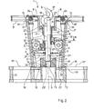
- the second embodiment of the coil 1 also consists of a core 2 with an upper flange 9 and a lower flange 12.
- the segments 3, which form the outer jacket of the coil core 2 are at the top Flange 9 hinged in bearings 24.
- Inside the core 2 are on the inside of the segments 3 rolls 5 stored. These rollers 5 run on their side facing away from the segment on a conical slider 4 which is displaceable in the direction of the longitudinal axis 6 of the coil.
- the sliding piece 4 is moved by moving a central axis 7 in a sliding guide 8 in the upper flange 9 up to an adjustable stop 8 1 .
- a roller bearing 10 is inserted between the axis 7 and the slider 4, which reduces the friction during the transmission of the compressive forces.
- the running surfaces for the rollers 5 on the slider 4 are designed in the exemplary embodiment as grooves in which the rollers 5 run. A rotation of the slider 4 with the axis 7 is thus excluded, whereas the axis 7 is easily rotatable.
- Tension springs 11 are arranged below the rollers 5 and the slider 4, one end of which is connected to the inside of a segment 3 and the other end of which is slidably connected to the axis 7. The springs 11 also serve here to retract the segments 3 when the slider 4 moves back in the direction of the upper flange 9 of the coil 1.
- the central axis 7 also has a thread 13 'at its lower end 7' which is used when the axis is rotated 7 engages in the corresponding threaded bore 13 in the lower flange 12. For secure positioning of the lower end 7 'of the axis 7 above the threaded bore 13, this again has a conically narrowing insertion 14.
- the lower flange 12 has on its core-side surface 12 'the annular groove 16, in which the lower ends 32 of the segments 3 engage.
- a corresponding annular groove 15 is also found in this exemplary embodiment on the core-side surface 9 'of the upper bottle 9 for receiving the upper ends 31 of the segments 3.
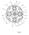
- FIG. 3 shows a section in a horizontal plane through the core 2 of the coil 1 according to FIG. 2 above the rollers 5.
- the rollers 5 are mounted on the inner sides of the segments 3 and run with their side facing away from the segment on the slide 4. In the center, the rotatable axis 7 for displacing the slide 4 can be seen.
- the slots 18 already mentioned can be seen, which are aligned with the grooves 19 in the outside of the core 2 and are used for the passage of packaging bandages for securing the wound coil.
- the lower flange 12 also has slots which are aligned with the slots 18 of the upper flange 9 and the grooves 19 in the outside 2 'of the core 2 and also serve to carry out packaging bandages.
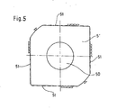
- FIG. 5 shows a skid 5 'in vertical section.
- These skids 5 ' can be used instead of the rollers 5 in the coil design according to FIGS. 2 and 3.
- the runners 5 ' have a central bore 50, the diameter of which corresponds to the diameter of the bearing bore of the roller 5.
- the runner 5 'advantageously has four sliding surfaces 51, one of which abuts the sliding piece 4. Subsequent wear can be used by turning the skid a new sliding surface without disassembling the coil. Due to the mobility of the runners 5 'around their central bores 50, an optimal surface contact between the runners 5' and the slider 4 is always ensured, so that even very large forces are transferred gently.
- the coil according to the invention can be realized in various designs, which results in a variety of possible uses. So
- the coils can be provided with a core that tapers conically upwards or downwards and with corresponding separation options for the core and one of the flanges.
Landscapes
- Storage Of Web-Like Or Filamentary Materials (AREA)
Applications Claiming Priority (2)
| Application Number | Priority Date | Filing Date | Title |
|---|---|---|---|
| DE3445802 | 1984-12-15 | ||
| DE19843445802 DE3445802A1 (de) | 1984-12-15 | 1984-12-15 | Spule fuer ein draht- oder kabel-coil |
Publications (1)
| Publication Number | Publication Date |
|---|---|
| EP0187311A1 true EP0187311A1 (fr) | 1986-07-16 |
Family
ID=6252866
Family Applications (1)
| Application Number | Title | Priority Date | Filing Date |
|---|---|---|---|
| EP85115948A Withdrawn EP0187311A1 (fr) | 1984-12-15 | 1985-12-13 | Bobine pour une couronne de fil métallique ou de câble |
Country Status (2)
| Country | Link |
|---|---|
| EP (1) | EP0187311A1 (fr) |
| DE (1) | DE3445802A1 (fr) |
Cited By (4)
| Publication number | Priority date | Publication date | Assignee | Title |
|---|---|---|---|---|
| EP0439811A1 (fr) * | 1990-01-31 | 1991-08-07 | IMPIANTI INDUSTRIALI Spa | Touret démontable pour fil métallique |
| EP1149794A3 (fr) * | 2000-03-06 | 2002-11-20 | Studio Tecnico Ruggenenti P.I. Leardo | Bobine en plusieurs parties pour couronne de fil métallique |
| CN105084127A (zh) * | 2015-08-27 | 2015-11-25 | 重庆雨帝建材有限公司 | 防水卷材内衬 |
| CN109677999A (zh) * | 2019-01-31 | 2019-04-26 | 江苏富天江电子电器有限公司 | 一种绕线机用自动循环变轨箱 |
Families Citing this family (1)
| Publication number | Priority date | Publication date | Assignee | Title |
|---|---|---|---|---|
| DE3817055A1 (de) * | 1988-05-19 | 1989-11-23 | Timmer Josef Gmbh | Drahtspule |
Citations (4)
| Publication number | Priority date | Publication date | Assignee | Title |
|---|---|---|---|---|
| FR2198484A5 (fr) * | 1972-09-05 | 1974-03-29 | Dioce Glaser Inc | |
| CH556291A (de) * | 1973-10-04 | 1974-11-29 | Madag Maschinen Apparatebau | Auf- bzw. abwickelvorrichtung fuer das praegeband bei praegemaschinen. |
| CH567998A5 (en) * | 1974-04-17 | 1975-10-15 | Aied Textile Mach | Bobbin winding arrangement with swinging release arm - handle allows boss and flange to swing back from bobbin |
| CH641741A5 (en) * | 1981-03-21 | 1984-03-15 | Andre Gonthier | Cylindrical reel having a retractible drum |
Family Cites Families (6)
| Publication number | Priority date | Publication date | Assignee | Title |
|---|---|---|---|---|
| DE568921C (de) * | 1930-11-07 | 1933-01-26 | Hermann Boecher | Senkrecht angeordneter Haspel fuer warmgewalzten Draht |
| US2695142A (en) * | 1950-06-08 | 1954-11-23 | United States Steel Corp | Collapsible take-up reel |
| US2789779A (en) * | 1955-05-03 | 1957-04-23 | Continental Steel Corp | Expansible and collapsible-core spool mechanism |
| US2971721A (en) * | 1957-06-26 | 1961-02-14 | Rome Cable Corp | Construction of coil blocks |
| US4140289A (en) * | 1977-11-28 | 1979-02-20 | Wyrepak Industries, Inc. | Disposable, wire storage and pay-out spool |
| DE2912806C2 (de) * | 1979-03-30 | 1983-03-31 | Industriewerk Nachf. Seifert & Co Kg, 8632 Neustadt | Zerlegbare Drahtspule |
-
1984
- 1984-12-15 DE DE19843445802 patent/DE3445802A1/de not_active Ceased
-
1985
- 1985-12-13 EP EP85115948A patent/EP0187311A1/fr not_active Withdrawn
Patent Citations (4)
| Publication number | Priority date | Publication date | Assignee | Title |
|---|---|---|---|---|
| FR2198484A5 (fr) * | 1972-09-05 | 1974-03-29 | Dioce Glaser Inc | |
| CH556291A (de) * | 1973-10-04 | 1974-11-29 | Madag Maschinen Apparatebau | Auf- bzw. abwickelvorrichtung fuer das praegeband bei praegemaschinen. |
| CH567998A5 (en) * | 1974-04-17 | 1975-10-15 | Aied Textile Mach | Bobbin winding arrangement with swinging release arm - handle allows boss and flange to swing back from bobbin |
| CH641741A5 (en) * | 1981-03-21 | 1984-03-15 | Andre Gonthier | Cylindrical reel having a retractible drum |
Cited By (5)
| Publication number | Priority date | Publication date | Assignee | Title |
|---|---|---|---|---|
| EP0439811A1 (fr) * | 1990-01-31 | 1991-08-07 | IMPIANTI INDUSTRIALI Spa | Touret démontable pour fil métallique |
| EP1149794A3 (fr) * | 2000-03-06 | 2002-11-20 | Studio Tecnico Ruggenenti P.I. Leardo | Bobine en plusieurs parties pour couronne de fil métallique |
| CN105084127A (zh) * | 2015-08-27 | 2015-11-25 | 重庆雨帝建材有限公司 | 防水卷材内衬 |
| CN109677999A (zh) * | 2019-01-31 | 2019-04-26 | 江苏富天江电子电器有限公司 | 一种绕线机用自动循环变轨箱 |
| CN109677999B (zh) * | 2019-01-31 | 2023-12-22 | 江苏富天江电子电器有限公司 | 一种绕线机用自动循环变轨箱 |
Also Published As
| Publication number | Publication date |
|---|---|
| DE3445802A1 (de) | 1986-06-19 |
Similar Documents
| Publication | Publication Date | Title |
|---|---|---|
| DE9320412U1 (de) | Spule zur Aufnahme von langgestrecktem Wickelgut | |
| DE2846112C2 (de) | Vorrichtung zum Festkeilen von unter einem Flugzeug mitgeführten Lasten | |
| DE3809496C2 (de) | Ringwickelvorrichtung | |
| EP2428452B1 (fr) | Procédé et dispositif de banderolage pour l'installation de bandes de cerclage autour de pièces d'emballage | |
| DE2225555B2 (de) | Spulenhalter | |
| DE1158142B (de) | Maschine zum Aufwickeln von Kabeln, Seilen od. dgl. Stranggut auf eine mit Endflanschen versehene Trommel | |
| EP0187311A1 (fr) | Bobine pour une couronne de fil métallique ou de câble | |
| EP0413985B1 (fr) | Mandrin expansible pourvu de moyens de contraction en cas d'urgence pour un bobinoir de matériaux en bandes | |
| DE2112651B2 (de) | Spann- und Lösevorrichtung fur Werkzeuge an Bohr-, Fräs- u.dgl. Werkzeugmaschinen | |
| EP0070950A1 (fr) | Pince à prise interne pour le levage de charges, spécialement de rouleaux | |
| DE2420567A1 (de) | Wickelmaschine fuer bandmaterial | |
| DE1196929B (de) | Vorrichtung zum Auswechseln von Kabel-trommeln bei einer Wickelvorrichtung | |
| DE3723592C2 (fr) | ||
| DE4122567C2 (fr) | ||
| DE2211518B2 (de) | Vorrichtung zum Aufspannen von rohrförmigen Wickelkernen | |
| EP0030223A2 (fr) | Installation sur le chevalet de support et de guidage d'une installation de coulée continue | |
| DE2316950C3 (de) | Teilbare Maschinenspule | |
| DE2420584A1 (de) | Wickelmaschine fuer bandmaterial | |
| DE3341351A1 (de) | Lastaufnahmevorrichtung sowie ihre verwendung in einer hebevorrichtung | |
| EP3412402B1 (fr) | Technique de remplissage d'un dispositif automatique de placement de composants | |
| DE19750782B4 (de) | Spule | |
| DE69020881T2 (de) | Abmontierbare Drahtspule. | |
| DE69310426T2 (de) | Präzisionsdorn, insbesondere für Wickelmaschinen | |
| EP4670863A1 (fr) | Dispositif et procédé d'enroulement d'un produit laminé en forme de bande sur un mandrin ou un manchon d'un dispositif enrouleur | |
| EP0431476A1 (fr) | Dispositif et méthode pour enrouler une bande |
Legal Events
| Date | Code | Title | Description |
|---|---|---|---|
| PUAI | Public reference made under article 153(3) epc to a published international application that has entered the european phase |
Free format text: ORIGINAL CODE: 0009012 |
|
| AK | Designated contracting states |
Kind code of ref document: A1 Designated state(s): AT BE CH DE FR GB IT LI LU NL SE |
|
| STAA | Information on the status of an ep patent application or granted ep patent |
Free format text: STATUS: THE APPLICATION IS DEEMED TO BE WITHDRAWN |
|
| 18D | Application deemed to be withdrawn |
Effective date: 19870117 |
|
| RIN1 | Information on inventor provided before grant (corrected) |
Inventor name: KREUZNACHT, JULIUS Inventor name: GAUSLING, EDUARD |