EP0187320A1 - Article de chauffage à autorégulation avec des électrodes connectées directement à une couche PTC - Google Patents
Article de chauffage à autorégulation avec des électrodes connectées directement à une couche PTC Download PDFInfo
- Publication number
- EP0187320A1 EP0187320A1 EP85116105A EP85116105A EP0187320A1 EP 0187320 A1 EP0187320 A1 EP 0187320A1 EP 85116105 A EP85116105 A EP 85116105A EP 85116105 A EP85116105 A EP 85116105A EP 0187320 A1 EP0187320 A1 EP 0187320A1
- Authority
- EP
- European Patent Office
- Prior art keywords
- layer
- layers
- self
- regulating heating
- heating article
- Prior art date
- Legal status (The legal status is an assumption and is not a legal conclusion. Google has not performed a legal analysis and makes no representation as to the accuracy of the status listed.)
- Granted
Links
Images


Classifications
-
- H—ELECTRICITY
- H01—ELECTRIC ELEMENTS
- H01C—RESISTORS
- H01C1/00—Details
- H01C1/14—Terminals or tapping points specially adapted for resistors; Arrangements of terminals or tapping points on resistors
- H01C1/1406—Terminals or electrodes formed on resistive elements having positive temperature coefficient
-
- H—ELECTRICITY
- H05—ELECTRIC TECHNIQUES NOT OTHERWISE PROVIDED FOR
- H05B—ELECTRIC HEATING; ELECTRIC LIGHT SOURCES NOT OTHERWISE PROVIDED FOR; CIRCUIT ARRANGEMENTS FOR ELECTRIC LIGHT SOURCES, IN GENERAL
- H05B3/00—Ohmic-resistance heating
- H05B3/02—Details
- H05B3/06—Heater elements structurally combined with coupling elements or holders
-
- H—ELECTRICITY
- H05—ELECTRIC TECHNIQUES NOT OTHERWISE PROVIDED FOR
- H05B—ELECTRIC HEATING; ELECTRIC LIGHT SOURCES NOT OTHERWISE PROVIDED FOR; CIRCUIT ARRANGEMENTS FOR ELECTRIC LIGHT SOURCES, IN GENERAL
- H05B3/00—Ohmic-resistance heating
- H05B3/10—Heating elements characterised by the composition or nature of the materials or by the arrangement of the conductor
- H05B3/12—Heating elements characterised by the composition or nature of the materials or by the arrangement of the conductor characterised by the composition or nature of the conductive material
- H05B3/14—Heating elements characterised by the composition or nature of the materials or by the arrangement of the conductor characterised by the composition or nature of the conductive material the material being non-metallic
- H05B3/146—Conductive polymers, e.g. polyethylene, thermoplastics
Definitions
- the present invention relates to a layered heating article formed of a material exhibiting a positive temperature coefficient of resistance.
- the present invention relates generally to heating elements, and more particularly to a self-regulating heating article which utilizes a material exhibiting positive temperature coefficient (PTC) of resistance.
- PTC positive temperature coefficient
- the distinguishing characteristic of PTC materials is' that on reaching a certain temperature (switching temperature), a sharp rise in resistance occurs and the heating article utilizing such materials switches off.
- the thermal resistance between electrodes be as small as possible for higher efficient operation. Improvement in the manufacture of PTC heating appliances is further desired for cost reduction.
- ThIs object is Attained by a self-regulating heating article which comprises a first elongate layer comprising a crystalline polymeric composition of high crystallinity and conductive particles dispersed in the polymeric composition to exhibit a positive temperature coefficient of resistance.
- a pair of elongate electrodes which are adapted for connection to a mains supply, are secured one on each surface of the first layer to develop a potential in the direction of thickness of the first layer.
- the electrodes are arranged so that a creeping distance which is greater than the thickness of the first layer is established between the electrodes along peripheral edges thereof. The creeping distance prevents insulation breakdown and ensures safe, high wattage operation at mains supply voltages.
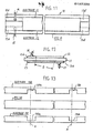
- FIGs. 1 and 2 there is shown a layered self-regulating heating article 10 according to an embodiment of the present invention in the form of a 300-mm long and 10-mm wide strip.
- Heating strip 10 has such a thickness that it can flex to adopt the shape of an article to be heated.
- heating strip 10 may be sandwiched between metal plates for space heating.
- Heating strip 10 comprises a resistance layer 11 of material having a positive temperature coefficient (PTC) of resistance.
- PTC resistance layer 11 is sandwiched between an upper conductive layer or electrode 12 and a lower conductive layer or electrode 13 which is indicated by a dotted-line in Fig. 1.
- Electrodes 1 2 and 13 are adapted for connection to mains supply, which is typically in the range between 100 and 200 volts, through lead wires 14, 15 connected by soldered joints as at 16 and 17, respectively.
- Upper layer 12 is offset inwardly by 2.5 mm along all the edges thereof from the peripheral edges of the PTC layer 11 to provide a sufficient "creeping distance" of 2.8 mm between the electrodes 12 and 13 to ensure electrical . insulation.
- the creeping distance is the shortest distance along which current would seek a low impedance path which might exist between the electrodes when potential is applied thereacross.
- resistance layer 11 having a thickness smaller than 3 mm, preferably, 1 mm or less, and a thermal resistance of 0.02 m 2 h o C/Kcal gives high wattage levels with uniform heat distributions.
- the thickness of PTC resistance layer 11 is 0.3 mm.
- Resistance layer 11 is formed of a resin of high crystallinity capable of withstanding high potentials and 30 weight-percent of carbon black particles having a substantially spherical shape with an average size of more than 0.05 micrometers, typically 0.1 micrometers, uniformly dispersed in substantial contact with one another.
- the carbon black particles form conductive networks through the resin matrix to establish an initially low resistivity at lower temperatures.
- the resin's matrix rapidly expands, causing a breakup of many of the conductive networks due to the difference in thermal expansion between the two materials, which in turn results in a sharp increase in the resistance of the composition to a resistivity which is 10 4 to 10 6 times higher than the room temperature value.
- the resin suitable for the present invention has a high degree of crystallization, typically 20 percent or more according to X-ray analysis.
- Suitable materials for the resin include polyolefins such as ethylene-vinyl acetate copolymers, ethylene-ethyl acrylate copolymers, ionomer polyethylene, polypropylene and the like, and crystalline resins such as polyamides, halogenated vinylidene resins, polyesters and the like.
- Crosslinking agent or filler may be added to avoid deformation of the PTC element and to keep it from exhibiting a negative temperature characteristic.
- Coupling agent may also be added or graft polymerization may be provided to enhance the bond between the particulate carbon and resin matrix.
- the PTC element can be made to exhibit a sharper increase in resistivity which is 10 times higher than the room temperature resistivity.
- the heating article 10 showed an initial wattage of 6 watts/cm 2 and levelled off to a steady value of 2 watts/cm 2 .
- a temperature gradient of lower than 3 0 C was observed between the electrodes 12 and 13, and a temperature of as high as 100°C was obtained on both sides of the strip 10. The fact that the temperature gradient is 3 0 C indicantes that no "hotline" problem takes place.
- the heating article was impressed with AC potentials of 200 volts, 250 volts, 300 volts and finally 500 volts, in succession, but abnormal leakage current was' not observed.
- Resistance layer 11 is made by a long strip of the PTC material mentioned above using an extrusion molding process and continuously cemented to long conductive strips on opposite sides by thermosetting or using a conductive adhesive agent to provide an elongate metal-backed structure. The latter is then cut into segments of desired length, typically 300 mm intervals, as mentioned above.
- the upper and lower electrodes 12, 13 are offset by 1.5 mm on all their edges from the peripheral edges of the 0.3-mm thick PTC layer 11.
- the creeping distance of this embodiment is 3.3 mm. It is obvious that the electrodes are not necessarily centered with respect to the PTC strip 11 in so far as the creeping distance is ensured.
- the upper and lower electrodes 12, 13 are offset by 2.5 mm from the right and left longitudinal edges of the 03-mm thick PTC layer 11, respectively, to give a creeping distance of 2.8 mm.
- This embodiment is preferred in favor of the previous embodiments in that the longitudinal edges of the PTC strip 11 are reenforced by the backing conductive layer and conductive strips of same width can be used for the electrodes.
- Electrodes 12 and 13 are provided respectively with lateral projections 12a and 13a extending laterally in opposite directions to each other to present a surface sufficient for soldering operation and to permit the soldering machine to be accessed thereto in the same direction. Since soldering material tends to be heated by a c'urrent passing through it and since the lateral projections 1'2a and 13a are not in thermal contact with the PTC layer 11, the latter is protected from excessive heat developed in the soldered contact portions..
- the upper electrode 12 is offset at its right-end edge 12b and the lower electrode 13 is offset at its left-end edge 13b to expose the PTC layer 11 at end portions lla and llb.
- Lead wire 14 is soldered on a portion of the upper electrode 12 which is overlying the exposed portion llb of the PTC layer 11 and lead wire 15 is soldered on a portion of the lower electrode 13 which is underlying the exposed portion 1la of the PTC layer 11.
- soldered joints 16 and 17 are heated excessively and the desired characteristics of the PTC layer are destroyed at portions lla and llb to the detriment of their insulation, such insulation failure will be confined to localized areas and shorting between electrodes 12 and 13 through the failed part of the PTC layer can be avoided due to the absence of an adjacent counterelectrode.
- the upper and lower electrodes 12, 13 are formed with windows 12c and 13c, respectively, in positions adjacent the left- and right-end edges of the heating strip 10.
- Lead wire 14 is soldered in the portion of the electrode 12 below which the window 13c is formed and lead wire 15 is soldered in the portion of the electrode 13 above which the window 12c is provided.
- the individual heating segments have sufficient creeping distance with respect to their longitudinal edges. However, if the angle of cut is perpendicular to the surface of the workpiece, the creeping distance is not sufficient with respect to the edges at each end thereof.
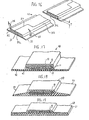
- Figs. 8 to 10 illustrate embodiments having bevelled edges at opposite ends to provide the necessary creeping distance in efficient manner.
- each end of the strip 10 having a 0.5-mm thick PTC layer 11 has a bevelled edge inclined at an angle, typically at 11 degrees, to the length thereof to provide a creeping distance of 2.6 mm, for example.
- Lead wires 14 and 15 are soldered to the bevelled surfaces of electrodes 12 and 13, respectively, and insulating thermosetting material is molded on the bevelled edges as shown at 20 and 21 to conceal the soldered portions.
- the bevelled surface can be formed by tilting the angle of cut when the long composite strip is cut into the individual segments.
- the creeping distance can be lengthened by forming curved surfaces as shown at Fig. 9 to increase the creeping distances.
- each end of the segmented strip may be formed into the shape of a staircase using a milling machine as shown in Fig. 10. The creeping distance is, of course, determined by the steps formed in the PTC layer 11.
- Embodiments shown in Figs. 11 to 15 provide the necessary creeping distance at opposite ends of the segmented heating strip with the angle of cut being maintained at 90 degrees to the length of the strip.
- Electrode 12 of the Fig. 11 embodiment has a narrow end portion 12d at the left end and narrow end portion 12d' at the right end which is one-half the length of the portion 12d.
- electrode 13 has a narrow end portion 13d at the left end and a narrow end portion 13d' at the right end, the portions 13d and 13d' being displaced transversely from the end portions 12d and 12d', respectively.
- Lead wires 14 and 15 are soldered to the longer end portions 12d and 13d, respectively.
- the creeping distance D at each end of the article 10 is measured between the end portions 12d and 13d as shown in Fig. 12. As shown in Fig. 13, the Fig.
- 11 embodiment is fabricated by preparing a long strip of conductor 120 having cutout portions 120a formed at longitudinal intervals and a second long strip of conductor 130 having similar cutout portions 130a.
- Conductors 120 and 130 are cemented on the opposite sides of a PTC strip 110 so that cutout portions 120a and 130a are aligned longitudinally with each other but not aligned transversely with each other.
- the layered structure is then cut at right angles thereto along chain-dot lines A which lie at one-third of the length of the cutouts.
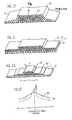
- the electrode 12 of the embodiment of Fig. 14 has a narrow end portion 12e at the left end and a narrow end portion 12e' at the right end which is one-half the length of the end portion 12e.
- Electrode 13 has a pair of transversely spaced narrow end portions 13e at the left end and a pair of transversely spaced narrow end portions 13e at the right end. End portions 12e and 12e' are not aligned with the end portions 13e and 13e' to provide the necessary creeping distance.
- the Fig. 14 embodiment is fabricated by preparing a long strip of conductor 121 as shown in Fig.
- the layered structure is cut into segments along lines B which lie at one-third of the length of the cutout 121a.
- Figs. 11 and 14 are also protected from insulation breakdown which might occur as a result of excessive heat generated by soldered joints in a manner identical to the embodiments of Figs. 6 and 7.
- Fig. 16 is a modification of the Fig. 11 embodiment.
- heating article 10 is formed by a PTC layer 31 having a shallow recess 31a on the upper surface thereof with the boundary between it and the land portion 31b following a curve generally similar to the contour line of the electrode 12 of Fig. 11.
- Upper electrode 32 has a contour line identical to the contour line of the recess 31a and a stepped portion along the longitudinal straight edge.
- the upper portion of electrode 32 is cemented to the recess 31a of PTC layer 31 and the stepped portion to a longitudinal edge thereof, so that the upper surface of electrode 32 and the land portion 3lb of PTC layer 31 are even with each other concealing the edge of electrode 32 in the recess and the flang portion of electrode 32 made flush with the lower surface of PTC layer 31.
- PTC layer 31 is further formed with a recess 31c on the lower surface thereof.
- Lower electrode 33 is cemented to the recess 31c presenting a flat surface with the PTC layer 31 so that a portion of the electrode 33 forms a flange on the opposie side to the flange of upper electrode 32.
- Lead wires 34 and 35 are attached to the flanges of electrodes 32 and 33, respectively.
- each of the electrodes 32, 33 meets with the adjoining surface is spaced from the opposite electrode at a distance which is at least equal to the creeping distance which in turn is greater than the thickness T of the portion of P T C layer 31 where upper and lower electrodes 32, 33 overlap.
- Fig. 17 shows an insulated heating article 40 which comprises the metal-backed heating strip 10 enclosed with a polyvinylchloride layer 41 and cemented to a base 42 having a larger fluxual rigidity than layer 41 to enable it to be worked with ease.
- Article 40 is attached to an object to be heated with the base 42 being in contact with it.
- Enclosure 41 serves to confine heat generated by PTC layer 11 and base 42 serves as an energy diffusion surface to uniformly transfer the confined energy to the object being heated.
- the heating article 10 may be enclosed in a mold as shown at 50 in Fig. 18.
- the mold 50 is shaped to form a pair of flanges 51, 52 which are outwardly tapered in thickness and presents a sufficient contact surface with an object to be heated for efficient heat diffusion and transfer.
- metal-backed strip 10 is sandwiched between resin films 60 and 61.
- Film 61 has a thickness 1.5 times greater than the thickness of film 60 and a flexual rigidity three times greater than that of film 60.
- Films 60 and 61 extend laterally and are cemented together to form a thin laminated structure.
- High rigidity inorganic material such as mica can also be used for film 61.
- FIG. 20 An embodiment shown in Fig. 20 is similar to the Fig. 18 embodiment with the exception that it includes a thermally fused layer 53 interposed between the metal-backed strip 10 and the surrounding polyvinylchloride mold 50.
- Fusable layer 53 is formed of a resin having a lower melting point than mold 50 to serve as a cushion for working the molded heating article. This layer 53 also functions as a filler to fill in any interstices which might exist to reduce the thermal resistance.
- Such fusable material can also be employed as shown in Fig. 21 as a modification of Fig. 1 9 by forming fused layers 62 and 63 between layers 60 and 61. This structure permits the films 60 and 61 to be formed by an extrusion process.
- each of the previous embodiments is used as many as desired and arranged sidy by side on a large metal sheet.
- metal-backed PTC strip 10 is in contact with a highly conductive layer 70 having a larger surface than strip 10.
- Layer 70 is formed of a material such as aluminum, copper or iron to provide a heat diffusion function and is cemented to an insulating layer 71 having low thermal conductivity and a larger area than layer 70...
- Insulating plate 71 is secured to a heat radiation metal sheet 72 having a larger area than insulating plate 71.
- Heat generated by the PTC article 10 diffuses in all directions by diffusion layer 70 and conducted through insulating member 71 to the radiating surface 72.
- thermal energy is conducted to the radiating surface 72 with a minimum of loss.
- the provision of the diffusing layer 70 serves to distribute thermal energy uniformly over the surface of the radiating sheet 72 as favorably compared with the heat distribution which is obtained without the heat diffusion layer 70 as indicated by a broken-line curve 74. More specifically, the temperature is raised by 3°C on the average although there is a decrease at the center by 2°C. As a result, the heat radiating surface 72 is heated to a temperature approaching the self-regulating point of the PTC layer 11. A space heater having a large heat dissipation area can be accomplished by this embodiment.
- Fig. 24 is an illustration of a space heater employing a plurality of metal-backed heating articles 10 each having a 1-mm thick PTC layer.
- Articles 10 are arranged Bide by side between opposed aluminum heat radiation metal sheets 80 and 81.
- An interesting feature of this embodiment is that temperature difference measured across the opposite surfaces of the PTC layer 11 was one-fourth of the value which was obtained when one of the metal sheets 80, 81 was dispensed with. This means that for an apparatus having a pair of opposed heat radiating surfaces, the amount of thermal energy withdrawn from the PTC elements is four times greater than is possible with an apparatus having a single heat radiation surface.
- each of the metal-backed articles 10 is enclosed by an insulating layer 82 as shown in Fig. 25. This insulation is is preferred to coating the radiating surfaces with an insulating film.
- Fig. 25 is modified as shown in Fig. 26 in which the radiating surface 80 is formed into a corrugated shape to make contact with the opposite radiating surface 81. With this corrugation, any temperature difference which might develop between surfaces 80 and 81 can be uniformly distributed between them.
Landscapes
- Engineering & Computer Science (AREA)
- Microelectronics & Electronic Packaging (AREA)
- Resistance Heating (AREA)
Applications Claiming Priority (20)
| Application Number | Priority Date | Filing Date | Title |
|---|---|---|---|
| JP266665/84 | 1984-12-18 | ||
| JP266641/84 | 1984-12-18 | ||
| JP59266665A JPS61143984A (ja) | 1984-12-18 | 1984-12-18 | 正抵抗温度係数発熱体 |
| JP59266640A JPH0656792B2 (ja) | 1984-12-18 | 1984-12-18 | 正抵抗温度係数発熱体の製造方法 |
| JP266666/84 | 1984-12-18 | ||
| JP59266669A JPH0612689B2 (ja) | 1984-12-18 | 1984-12-18 | 正抵抗温度係数発熱体 |
| JP26664184A JPH0679499B2 (ja) | 1984-12-18 | 1984-12-18 | 正抵抗温度係数発熱体 |
| JP59266647A JPS61143981A (ja) | 1984-12-18 | 1984-12-18 | 正抵抗温度係数発熱体 |
| JP266640/84 | 1984-12-18 | ||
| JP266669/84 | 1984-12-18 | ||
| JP59266668A JPS61143987A (ja) | 1984-12-18 | 1984-12-18 | 発熱体 |
| JP266664/84 | 1984-12-18 | ||
| JP266647/84 | 1984-12-18 | ||
| JP266649/84 | 1984-12-18 | ||
| JP59266649A JPS61143982A (ja) | 1984-12-18 | 1984-12-18 | 発熱体 |
| JP59266666A JPS61143985A (ja) | 1984-12-18 | 1984-12-18 | 発熱体 |
| JP266668/84 | 1984-12-18 | ||
| JP59266664A JPS61143983A (ja) | 1984-12-18 | 1984-12-18 | 正抵抗温度係数発熱体 |
| JP60233618A JPH0740507B2 (ja) | 1985-10-18 | 1985-10-18 | 発熱体 |
| JP233618/85 | 1985-10-18 |
Publications (2)
| Publication Number | Publication Date |
|---|---|
| EP0187320A1 true EP0187320A1 (fr) | 1986-07-16 |
| EP0187320B1 EP0187320B1 (fr) | 1991-08-28 |
Family
ID=27580432
Family Applications (1)
| Application Number | Title | Priority Date | Filing Date |
|---|---|---|---|
| EP85116105A Expired EP0187320B1 (fr) | 1984-12-18 | 1985-12-17 | Article de chauffage à autorégulation avec des électrodes connectées directement à une couche PTC |
Country Status (4)
| Country | Link |
|---|---|
| US (2) | US4783587A (fr) |
| EP (1) | EP0187320B1 (fr) |
| CA (1) | CA1249323A (fr) |
| DE (1) | DE3583932D1 (fr) |
Cited By (2)
| Publication number | Priority date | Publication date | Assignee | Title |
|---|---|---|---|---|
| GB2196818A (en) * | 1986-10-13 | 1988-05-05 | Herush Electrical | Heating pad |
| GB2196215B (en) * | 1986-10-15 | 1991-01-09 | Jong Tsuen Lin | Structure of electric heater |
Families Citing this family (28)
| Publication number | Priority date | Publication date | Assignee | Title |
|---|---|---|---|---|
| CA1301228C (fr) * | 1987-12-08 | 1992-05-19 | James L. Claypool | Appareils de chauffage electrique laminaires |
| US4912286A (en) * | 1988-08-16 | 1990-03-27 | Ebonex Technologies Inc. | Electrical conductors formed of sub-oxides of titanium |
| US4904850A (en) * | 1989-03-17 | 1990-02-27 | Raychem Corporation | Laminar electrical heaters |
| JP2626041B2 (ja) * | 1989-04-06 | 1997-07-02 | 株式会社村田製作所 | 有機正特性サーミスタ |
| AU637370B2 (en) * | 1989-05-18 | 1993-05-27 | Fujikura Ltd. | Ptc thermistor and manufacturing method for the same |
| US5113058A (en) * | 1990-06-01 | 1992-05-12 | Specialty Cable Corp. | PCT heater cable composition and method for making same |
| US5436609A (en) * | 1990-09-28 | 1995-07-25 | Raychem Corporation | Electrical device |
| US5089801A (en) * | 1990-09-28 | 1992-02-18 | Raychem Corporation | Self-regulating ptc devices having shaped laminar conductive terminals |
| US5432323A (en) * | 1994-01-07 | 1995-07-11 | Sopory; Umesh K. | Regulated electric strip heater |
| TW309619B (fr) * | 1995-08-15 | 1997-07-01 | Mourns Multifuse Hong Kong Ltd | |
| WO1997006660A2 (fr) * | 1995-08-15 | 1997-02-27 | Bourns, Multifuse (Hong Kong), Ltd. | Dispositifs polymeriques conducteurs pour montage en surface et procede de fabrication |
| US6020808A (en) | 1997-09-03 | 2000-02-01 | Bourns Multifuse (Hong Kong) Ltd. | Multilayer conductive polymer positive temperature coefficent device |
| US6172591B1 (en) | 1998-03-05 | 2001-01-09 | Bourns, Inc. | Multilayer conductive polymer device and method of manufacturing same |
| US6242997B1 (en) | 1998-03-05 | 2001-06-05 | Bourns, Inc. | Conductive polymer device and method of manufacturing same |
| US6236302B1 (en) | 1998-03-05 | 2001-05-22 | Bourns, Inc. | Multilayer conductive polymer device and method of manufacturing same |
| DE19836148A1 (de) * | 1998-08-10 | 2000-03-02 | Manfred Elsaesser | Widerstandsflächenheizelement |
| KR20010079908A (ko) | 1998-09-25 | 2001-08-22 | 추후보정 | 정의 온도 계수 폴리머 재료 제조 방법 |
| US5963121A (en) * | 1998-11-11 | 1999-10-05 | Ferro Corporation | Resettable fuse |
| US6429533B1 (en) | 1999-11-23 | 2002-08-06 | Bourns Inc. | Conductive polymer device and method of manufacturing same |
| KR100429382B1 (ko) * | 2001-12-17 | 2004-04-29 | 삼화콘덴서공업주식회사 | 엑시알 타입의 폴리머 정온도계수 저항소자 |
| EP1467599B1 (fr) * | 2003-04-12 | 2008-11-26 | Eichenauer Heizelemente GmbH & Co.KG | Dispositif pour l'admission des éléments de chauffe en céramique et procédé pour la production de tels |
| US20110198341A1 (en) * | 2010-02-17 | 2011-08-18 | Donald Allen Gilmore | Constant watt-density heating film |
| US8927910B2 (en) * | 2011-04-29 | 2015-01-06 | Board Of Regents Of The Nevada System Of Higher Education, On Behalf Of The University Of Nevada, Reno | High power-density plane-surface heating element |
| US10433371B2 (en) * | 2013-06-23 | 2019-10-01 | Intelli Particle Pty Ltd | Electrothermic compositions |
| US11578213B2 (en) | 2013-06-26 | 2023-02-14 | Intelli Particle Pty Ltd | Electrothermic compositions |
| CN109561526B (zh) * | 2017-09-26 | 2023-04-25 | 杜邦电子公司 | 加热元件和加热装置 |
| WO2020005151A1 (fr) * | 2018-06-25 | 2020-01-02 | Pelen Pte Ltd | Dispositif de chauffage et pellicule chauffante |
| DE102022125637A1 (de) * | 2022-10-05 | 2024-04-11 | Eberspächer Catem Gmbh & Co. Kg | PTC-Heizvorrichtung und Verfahren zu deren Herstellung |
Citations (10)
| Publication number | Priority date | Publication date | Assignee | Title |
|---|---|---|---|---|
| US3221145A (en) * | 1963-09-06 | 1965-11-30 | Armstrong Cork Co | Laminated heating sheet |
| US3397302A (en) * | 1965-12-06 | 1968-08-13 | Harry W. Hosford | Flexible sheet-like electric heater |
| US3564199A (en) * | 1968-12-30 | 1971-02-16 | Texas Instruments Inc | Self-regulating electric fluid-sump heater |
| FR2165943A1 (fr) * | 1971-12-27 | 1973-08-10 | Texas Instruments Inc | |
| AT325176B (de) * | 1972-05-05 | 1975-10-10 | Oppitz Hans | Flachenformiges heizelement |
| EP0019376A1 (fr) * | 1979-04-28 | 1980-11-26 | Murata Manufacturing Co., Ltd. | Appareil de chauffage employant un thermistor |
| EP0022611A1 (fr) * | 1979-05-21 | 1981-01-21 | RAYCHEM CORPORATION (a California corporation) | Dispositifs électriques comprenant des éléments CTP en polymère conducteur |
| EP0026457A2 (fr) * | 1979-09-28 | 1981-04-08 | Siemens Aktiengesellschaft | Dispositif de chauffage avec élément chauffant utilisant une résistance CTP |
| DE3042420A1 (de) * | 1980-11-11 | 1982-06-24 | Fritz Eichenauer GmbH & Co KG, 6744 Kandel | Elektrischer heizkoerper mit ein oder mehreren flachen, quaderfoermigen heizelementen |
| DE3311803A1 (de) * | 1983-03-31 | 1984-10-11 | Stettner & Co, 8560 Lauf | Elektrische heizvorrichtung, insbesondere fuer spiegel |
Family Cites Families (8)
| Publication number | Priority date | Publication date | Assignee | Title |
|---|---|---|---|---|
| US3243753A (en) * | 1962-11-13 | 1966-03-29 | Kohler Fred | Resistance element |
| US3410984A (en) * | 1966-05-03 | 1968-11-12 | Gen Electric | Flexible electrically heated personal warming device |
| US4177376A (en) * | 1974-09-27 | 1979-12-04 | Raychem Corporation | Layered self-regulating heating article |
| US4330703A (en) * | 1975-08-04 | 1982-05-18 | Raychem Corporation | Layered self-regulating heating article |
| US4327351A (en) * | 1979-05-21 | 1982-04-27 | Raychem Corporation | Laminates comprising an electrode and a conductive polymer layer |
| US4545926A (en) * | 1980-04-21 | 1985-10-08 | Raychem Corporation | Conductive polymer compositions and devices |
| US4317027A (en) * | 1980-04-21 | 1982-02-23 | Raychem Corporation | Circuit protection devices |
| US4517449A (en) * | 1983-05-11 | 1985-05-14 | Raychem Corporation | Laminar electrical heaters |
-
1985
- 1985-12-17 DE DE8585116105T patent/DE3583932D1/de not_active Expired - Lifetime
- 1985-12-17 US US06/809,966 patent/US4783587A/en not_active Expired - Lifetime
- 1985-12-17 EP EP85116105A patent/EP0187320B1/fr not_active Expired
- 1985-12-18 CA CA000497966A patent/CA1249323A/fr not_active Expired
-
1988
- 1988-05-05 US US07/190,562 patent/US4954696A/en not_active Expired - Lifetime
Patent Citations (10)
| Publication number | Priority date | Publication date | Assignee | Title |
|---|---|---|---|---|
| US3221145A (en) * | 1963-09-06 | 1965-11-30 | Armstrong Cork Co | Laminated heating sheet |
| US3397302A (en) * | 1965-12-06 | 1968-08-13 | Harry W. Hosford | Flexible sheet-like electric heater |
| US3564199A (en) * | 1968-12-30 | 1971-02-16 | Texas Instruments Inc | Self-regulating electric fluid-sump heater |
| FR2165943A1 (fr) * | 1971-12-27 | 1973-08-10 | Texas Instruments Inc | |
| AT325176B (de) * | 1972-05-05 | 1975-10-10 | Oppitz Hans | Flachenformiges heizelement |
| EP0019376A1 (fr) * | 1979-04-28 | 1980-11-26 | Murata Manufacturing Co., Ltd. | Appareil de chauffage employant un thermistor |
| EP0022611A1 (fr) * | 1979-05-21 | 1981-01-21 | RAYCHEM CORPORATION (a California corporation) | Dispositifs électriques comprenant des éléments CTP en polymère conducteur |
| EP0026457A2 (fr) * | 1979-09-28 | 1981-04-08 | Siemens Aktiengesellschaft | Dispositif de chauffage avec élément chauffant utilisant une résistance CTP |
| DE3042420A1 (de) * | 1980-11-11 | 1982-06-24 | Fritz Eichenauer GmbH & Co KG, 6744 Kandel | Elektrischer heizkoerper mit ein oder mehreren flachen, quaderfoermigen heizelementen |
| DE3311803A1 (de) * | 1983-03-31 | 1984-10-11 | Stettner & Co, 8560 Lauf | Elektrische heizvorrichtung, insbesondere fuer spiegel |
Cited By (3)
| Publication number | Priority date | Publication date | Assignee | Title |
|---|---|---|---|---|
| GB2196818A (en) * | 1986-10-13 | 1988-05-05 | Herush Electrical | Heating pad |
| GB2196818B (en) * | 1986-10-13 | 1990-03-28 | Herush Electrical | Electrical heaters |
| GB2196215B (en) * | 1986-10-15 | 1991-01-09 | Jong Tsuen Lin | Structure of electric heater |
Also Published As
| Publication number | Publication date |
|---|---|
| US4783587A (en) | 1988-11-08 |
| CA1249323A (fr) | 1989-01-24 |
| DE3583932D1 (de) | 1991-10-02 |
| US4954696A (en) | 1990-09-04 |
| EP0187320B1 (fr) | 1991-08-28 |
Similar Documents
| Publication | Publication Date | Title |
|---|---|---|
| US4783587A (en) | Self-regulating heating article having electrodes directly connected to a PTC layer | |
| KR100337609B1 (ko) | 세라믹 탄소섬유지 면상발열체 | |
| US3221145A (en) | Laminated heating sheet | |
| US4654511A (en) | Layered self-regulating heating article | |
| EP0417097B1 (fr) | Element chauffant et procede de fabrication d'un tel element | |
| US4543474A (en) | Layered self-regulating heating article | |
| US4330703A (en) | Layered self-regulating heating article | |
| EP0202896A2 (fr) | Elément chauffant électrique en forme de feuille | |
| US4904850A (en) | Laminar electrical heaters | |
| US4849255A (en) | Electric resistance heater | |
| IE41728B1 (en) | Articles having a positive temperature coeficient of resistance | |
| GB2154407A (en) | Heating element and method of manufacture | |
| US4517449A (en) | Laminar electrical heaters | |
| US4425497A (en) | PTC Heater assembly | |
| US4774397A (en) | Electrical semiconductor resistance heater | |
| ZA200100940B (en) | Heating member with resistive surface. | |
| KR102133343B1 (ko) | 효율 개선형 ptc 난방필름 및 이의 제조방법 | |
| US4547659A (en) | PTC Heater assembly | |
| US5015986A (en) | Organic positive temperature coefficient thermistor | |
| US4548662A (en) | Method of providing a protective covering over a substrate | |
| EP0397685B1 (fr) | Radiateur electrique laminaire | |
| JPS61232590A (ja) | カ−ボンヒ−タ− | |
| JPH0311581A (ja) | 自己温度制御発熱体 | |
| JPH01151191A (ja) | 自己温度制御形面発熱体 | |
| JPS60130085A (ja) | Ptc素子を含む電気装置 |
Legal Events
| Date | Code | Title | Description |
|---|---|---|---|
| PUAI | Public reference made under article 153(3) epc to a published international application that has entered the european phase |
Free format text: ORIGINAL CODE: 0009012 |
|
| AK | Designated contracting states |
Kind code of ref document: A1 Designated state(s): DE GB |
|
| 17P | Request for examination filed |
Effective date: 19861006 |
|
| 17Q | First examination report despatched |
Effective date: 19880226 |
|
| GRAA | (expected) grant |
Free format text: ORIGINAL CODE: 0009210 |
|
| AK | Designated contracting states |
Kind code of ref document: B1 Designated state(s): DE GB |
|
| REF | Corresponds to: |
Ref document number: 3583932 Country of ref document: DE Date of ref document: 19911002 |
|
| PLBE | No opposition filed within time limit |
Free format text: ORIGINAL CODE: 0009261 |
|
| STAA | Information on the status of an ep patent application or granted ep patent |
Free format text: STATUS: NO OPPOSITION FILED WITHIN TIME LIMIT |
|
| 26N | No opposition filed | ||
| REG | Reference to a national code |
Ref country code: GB Ref legal event code: 746 Effective date: 19960820 |
|
| REG | Reference to a national code |
Ref country code: GB Ref legal event code: IF02 |
|
| PGFP | Annual fee paid to national office [announced via postgrant information from national office to epo] |
Ref country code: DE Payment date: 20041209 Year of fee payment: 20 |
|
| PGFP | Annual fee paid to national office [announced via postgrant information from national office to epo] |
Ref country code: GB Payment date: 20041215 Year of fee payment: 20 |
|
| PG25 | Lapsed in a contracting state [announced via postgrant information from national office to epo] |
Ref country code: GB Free format text: LAPSE BECAUSE OF EXPIRATION OF PROTECTION Effective date: 20051216 |
|
| REG | Reference to a national code |
Ref country code: GB Ref legal event code: PE20 |