EP0187336A2 - Montage de palier pour chariot de machine - Google Patents
Montage de palier pour chariot de machine Download PDFInfo
- Publication number
- EP0187336A2 EP0187336A2 EP85116222A EP85116222A EP0187336A2 EP 0187336 A2 EP0187336 A2 EP 0187336A2 EP 85116222 A EP85116222 A EP 85116222A EP 85116222 A EP85116222 A EP 85116222A EP 0187336 A2 EP0187336 A2 EP 0187336A2
- Authority
- EP
- European Patent Office
- Prior art keywords
- shaft
- bearing
- ways
- mentioned
- cartridge
- Prior art date
- Legal status (The legal status is an assumption and is not a legal conclusion. Google has not performed a legal analysis and makes no representation as to the accuracy of the status listed.)
- Granted
Links
- 230000000712 assembly Effects 0.000 claims description 10
- 238000000429 assembly Methods 0.000 claims description 10
- 230000001154 acute effect Effects 0.000 claims 3
- 230000036316 preload Effects 0.000 abstract description 7
- 230000003134 recirculating effect Effects 0.000 abstract description 5
- 238000010276 construction Methods 0.000 description 2
- 238000003754 machining Methods 0.000 description 2
- 238000012986 modification Methods 0.000 description 1
- 230000004048 modification Effects 0.000 description 1
- 230000000717 retained effect Effects 0.000 description 1
- 238000005096 rolling process Methods 0.000 description 1
Images

Classifications
-
- F—MECHANICAL ENGINEERING; LIGHTING; HEATING; WEAPONS; BLASTING
- F16—ENGINEERING ELEMENTS AND UNITS; GENERAL MEASURES FOR PRODUCING AND MAINTAINING EFFECTIVE FUNCTIONING OF MACHINES OR INSTALLATIONS; THERMAL INSULATION IN GENERAL
- F16C—SHAFTS; FLEXIBLE SHAFTS; ELEMENTS OR CRANKSHAFT MECHANISMS; ROTARY BODIES OTHER THAN GEARING ELEMENTS; BEARINGS
- F16C29/00—Bearings for parts moving only linearly
- F16C29/04—Ball or roller bearings
- F16C29/06—Ball or roller bearings in which the rolling bodies circulate partly without carrying load
- F16C29/0614—Ball or roller bearings in which the rolling bodies circulate partly without carrying load with a shoe type bearing body, e.g. a body facing one side of the guide rail or track only
- F16C29/0616—Ball or roller bearings in which the rolling bodies circulate partly without carrying load with a shoe type bearing body, e.g. a body facing one side of the guide rail or track only for supporting load essentially in a single direction
- F16C29/0619—Ball or roller bearings in which the rolling bodies circulate partly without carrying load with a shoe type bearing body, e.g. a body facing one side of the guide rail or track only for supporting load essentially in a single direction with rollers or needles
-
- F—MECHANICAL ENGINEERING; LIGHTING; HEATING; WEAPONS; BLASTING
- F16—ENGINEERING ELEMENTS AND UNITS; GENERAL MEASURES FOR PRODUCING AND MAINTAINING EFFECTIVE FUNCTIONING OF MACHINES OR INSTALLATIONS; THERMAL INSULATION IN GENERAL
- F16C—SHAFTS; FLEXIBLE SHAFTS; ELEMENTS OR CRANKSHAFT MECHANISMS; ROTARY BODIES OTHER THAN GEARING ELEMENTS; BEARINGS
- F16C29/00—Bearings for parts moving only linearly
- F16C29/008—Systems with a plurality of bearings, e.g. four carriages supporting a slide on two parallel rails
-
- F—MECHANICAL ENGINEERING; LIGHTING; HEATING; WEAPONS; BLASTING
- F16—ENGINEERING ELEMENTS AND UNITS; GENERAL MEASURES FOR PRODUCING AND MAINTAINING EFFECTIVE FUNCTIONING OF MACHINES OR INSTALLATIONS; THERMAL INSULATION IN GENERAL
- F16C—SHAFTS; FLEXIBLE SHAFTS; ELEMENTS OR CRANKSHAFT MECHANISMS; ROTARY BODIES OTHER THAN GEARING ELEMENTS; BEARINGS
- F16C29/00—Bearings for parts moving only linearly
- F16C29/12—Arrangements for adjusting play
Definitions
- This invention relates to a bearing assembly for a machine slide and, more specifically, to a bearing arrangement for accurately guiding a slide on a pair of ways.
- roller way bearings are mounted between the guiding surfaces of the ways and the slide for reducing the friction therebetween.
- the bearings are frequently in the form of recirculating linear roller bearing cartridges mounted on the slide and engaging the guide surfaces of the ways. While such arrangements perform satisfactorily on many machines, they frequently are costly, of complicated construction and require specially designed ways.
- such bearings do not always perform well in machines where an extremely high degree of accuracy of slide movement is necessary. To obtain an extremely high degree of accuracy of slide movement, preloading and fine adjustment of the bearing cartridges is essential.
- the present invention has for its primary object the provision of an anti-friction bearing assembly incorporating a recirculating bearing cartridge adapted to be mounted on a slide in a manner enabling preloading of the bearing to a predetermined safe extent.
- Another object of this invention is to provide a bearing assembly of the above type which can be manufactured economically and which is adapted to be used with conventional dovetail or rectangular ways.
- a further object of this invention is to provide a 'bearing assembly of the above type constructed to enable very precise alignment of a slide relative to the ways on which the slide is mounted.
- Another object of the present invention is to provide a bearing assembly of the type described which is self-aligning so as to accommodate for deflections resulting from loads applied to the slide on which the bearing assembly is mounted without imposing excessive or localized stresses on the assembly or on the ways of the machine.
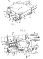
- FIG. 1 there is illustrated a machine 10 having a base 12 on which a pair of accurately parallel dovetail ways 14 are securely mounted.
- Each way 14 has a top flat guide surface 16 and a downwardly and laterally inwardly inclined flat guide surface 18.
- a slide 20 is guided for movement lengthwise of ways 14 by means of four bearing assemblies 22, mounted two at each side of the slide adjacent opposite ends thereof.
- the bearing assemblies 22 at one side of slide 20 are preferably aligned transversely with the bearing assemblies 22 on the opposite side of the slide.
- Each bearing assembly 22 comprises a support bracket 24 which, as shown in FIG. 2, includes an accurately machined rectangular top pad 26 having a pair of side plates 28 supported one at each end thereof by screws 30 and dowel pins 32.
- Top pad 26 has a plurality of openings 34 extending therethrough which are adapted to receive screws (not shown) for fixedly securing the brackets 28 to the underside of slide 20.
- An accurately machined rectangular slot 36 extends lengthwise in the bottom face of top pad 26.
- a linear roller bearing cartridge 38 of the recirculating type is mounted within slot 36 by screws 40 (FIG. 4),.
- the roller bearings 41 extending transversely along the bottom face of cartridge 38 form a flat bearing surface accurately perpendicular to the inner opposed faces of side plates 28 and adapted for accurate and smooth rolling engagement with the flat top surfaces 16 of ways 14.
- Each side plate 28 has a depending leg 42.
- Each leg 42 is formed with an accurately machined bore 44 which, when the side plates 28 are mounted on base 26, are accurately coaxial.
- a hardened shaft 46 threaded at each end as at 48 and having accurately ground cylindrical bearing portions 50 adjacent the threaded ends 48.
- Bearing portions 50 have a close fit in the bores 44.
- Shaft 46 has a central accurately ground cylindrical portion 52 which is eccentric relative to the opposite end portions of the shaft.
- the opposite ends of portion 52 terminate in flat shoulders 53 perpendicular to the axis of shaft 46.
- the length of eccentric portion 52 corresponds closely with the perpen- dicular distance between the inner opposed faces of the depending legs 42 of the side plates 28.
- the central axis of shaft 46 is desig- nated 56 and the central axis of the eccentric cylindrical portion 52 is designated 58.
- An adjusting block 60 is journalled on the eccentric portion 52 of shaft 46.
- Another linear roller bearing cartridge 62 of the recirculating type similar to cartridge 38 is mounted on the face 64 of adjusting block 60. Face 64 is accurately parallel to the central axis of the eccentric portion 52 of shaft 46.
- Cartridge 62 is mounted on face 64 by means of screws 66.
- the roller bearings 41 extending transversely across the top face of cartridge 62 form a flat bearing surface accurately parallel to the axis of shaft 46 and adapted to engage the inclined guide surfaces 18 of the two ways 14.
- the length of cartridge 62 and adjusting block 60 is slightly less than the length of the eccentric portion 52 of shaft 46.
- threaded openings 63 can be provided on the side plates 28 where desired to enable mounting dirt shields on the brackets as by screws 65.
- each of the above described components of support brackets 24 enable them to be machined and assembled easily and very accurately.
- the critical faces of the various components can be ground flat and to a highly accurate dimension with little difficulty.
- the various bores can be dimensioned and located very accurately. Therefore, when the components are assembled into a support bracket 24, dimensional tolerances in critical areas can be readily achieved.
- shaft 46 can be rotated in opposite directions to displace the bearing cartridges 62 on each of the support brackets toward and away from the inclined faces 18 of ways 14.
- the opposite ends of each shaft 46 are preferably slotted as at 74 for engagement with a screwdriver bit on a torque wrench.
- the ability to shift the cartridges 62 independently in this manner serves a two-fold function. It enables a desired preload to be applied to the bearing assemblies and also enables the longitudinal center line of the slide 20 to be accurately aligned with respect to the ways 14. For example, if the shafts 46 on the support brackets 24 at one side of slide 20 rotated such that the bearing cartridges thereon are retracted from the inclined face 18 of the associated way and the shafts of the brackets on the opposite side are rotated to drive the bearing cartridges against the inclined faces 18 of the other way, the entire slide would be shifted laterally on the two ways.
- the slide 20 can be rotated slightly in a horizontal plane on the two ways. While the range of this adjustment is small, nevertheless, in a normal assembly this adjustment range can be extremely fine and will make it possible to correct for machining errors.
- the limited rotational movement of shaft 46 and its arrangement on the support block 60 is very important.
- the two abutments 72 for the pin 68 are spaced angularly apart about 90° and the pin 68 is secured to the eccentric cylindrical portion 52 such that, when it is in its mid position of arcuate travel as shown in FIG. 6, the axis 56 of shaft 46 and the axis 58 of eccentric portion 52 lie in a plane generally parallel to the plane of the flat bearing surface defined by the roller bearings in cartridge 62.
- the shaft is prevented from rotating to a position wherein the axes 56,58 lie in a plane perpendicular to the plane of the bearing surface defined by the rollers of cartridge 62. It is important to prevent the shaft 46 from being rotated to a position approaching this "dead center" position so as to prevent the possibility of generating extremely large forces by the application of relatively low torque to the shafts. This avoids the possibility of accidentally damaging the bearings and/or the ways.
- the shafts in the brackets 24 are rotated in one direction or the other to the desired extent to obtain the desired preload and to obtain the proper alignment of the slide on the ways, the shafts may be locked in their adjusted position by tightening nuts 78 on the threaded ends of the shafts against the outer faces of the legs 42 of the side plates with a lock washer 80 therebetween.
- the assembled length of adjusting block 60 and cartridge 62 is slightly less than the length of the eccentric cylindrical portion 52 of shaft 46.
- the length of the eccentric portion 52 corresponds very closely to the distance between the inner faces of side plates 28.
- the cartridge 62 can rotate slightly on the eccentric portion 52 of shaft 46 so as to maintain the rollers therein in flat bearing engagement with the inclined faces 18 of the ways even though the shaft is locked against rotation. If the cartridges 62 were unable to rotate relative to shafts 46, an excessive lateral or transverse force on the slide could result in only one end of the rollers engaging the inclined faces 18 of the ways and, thus, produce excessive localized forces resulting in bearing failure and/or damage to the ways.
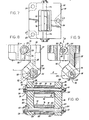
- the mounting bracket 80 is manufactured as one piece rather than a three-piece assembly as shown in FIGS. 1 thru 6 and includes a base flange 82 formed with through openings 84 for accommodating screws to mount the assembly on a slide.
- Bracket 80 includes a pair of spaced-apart depending legs 86, the upper portions of which are interconnected by a transverse web 88.
- the base flange 82 of bracket 80 is formed with a generally rectangularly shaped through opening 90 for accommodating a bearing assembly 92 which includes a roller way bearing cartridge 94 secured by suitable screws (not illustrated) to an adjusting block 96.
- adjusting block 96 is journalled for rotation on a cylindrical bushing 98.
- Bushing 98 is in turn eccentrically and non-rotatably mounted on a shaft 100. While any suitable means may be employed for non-rotatably mounting bushing 98 on shaft 100, a simple expedient for effecting this connection resides in forming a flat 102 lengthwise on shaft 100 and machining a hole in cylinder 98 which corresponds in cross section with shaft 102. In FIG. 9 the hole in the bushing 98 is designated 104.
- Shaft 100 is supported in accurately aligned bores 106 in base plate 82. The axis of bores 106 is accurately parallel to the top mounting face 108 of bracket 82. Shaft 100 is in the form of an accurately ground stud threaded at one end as at 110 and having an enlarged non-circular head 112 at its opposite end.
- Washer 114 is formed with an arcuate slot 116 which extends for about 90° around its periphery. The opposite ends of slot 116 limit the rotation of shaft 100 by abutting against a stop pin 118 in a manner and for the same purpose as the arrangement of pin 68 in arcuate slot 70 in the embodiment illustrated in FIG. 6.
- This pin and slot arrangement prevents the shaft 100 and the bushing 98 eccentrically mounted thereon from approaching a dead center position.
- bearing assembly 92 which, like the bearing assembly previously described, includes a shaft 100, a cylindrical bushing 98 eccentrically mounted thereon, an adjusting block 96 journalled on bushing 98, and a roller way bearing cartridge 94 secured to adjusting block 96.
- the lower shaft 100 is supported within aligned bores 120 formed adjacent the lower ends of the spaced-apart legs 86.
- a stop pin 122 is mounted on one of the legs 86 to limit rotation of the bearing assembly 92. In all' respects adjustment of the lower bearing assembly is substantially the same as the upper bearing assembly as previously described.
- one or both ends of the slide can be raised and lowered relative to the opposite end of the slide or the opposite side of the slide.
- the upper bearing assembly is adjusted to the desired.position the nut 124 on the threaded end of the shaft can be tightened to retain this position.
- the lower bearing assembly 92 can be adjusted to obtain the desired preload relative to the way in the manner previously described with reference to FIGS. 1 thru 6 and the nut 124 on the lower shaft can be tightened to retain the associated bearing assembly in a locked position.
- the opposed confronting faces on base plate 82 within opening 90 and the inner opposed confronting faces at the lower ends of legs 86 are formed with pads 126.
- the faces of pads 126 are accurately perpendicular to the axes of shafts 100 and the faces 126 are spaced apart a precise distance.
- the cylindrical bushings 98 are dimensioned in length to have a close fit between pads 126, whereas the adjusting blocks 96 and the cartridges 94 are slightly shorter than bushings 98 so that the bearing cartridges are free to rotate on bushings 98.
- bracket 82 enables the pads 126 to be machined very precisely to the desired dimensions.
- the critical faces of the various components of the embodiment shown in FIGS. 7 thru 10 can likewise be machined to very accurate dimensions with little difficulty.
- the required bores can likewise be dimensioned and located very accurately on the various components of the assembly.
- each bracket 24,80 is designed to support either one or two sets of bearing cartridges, the cartridges in each set being opposed so as to provide two parallel spaced, flat bearing surfaces.
- One or both cartridges in each set is similarly supported for rotation on the eccentric portions on shafts 46,100.
- the four cartridges are perpendicularly related to engage all four guide faces of a rectangular way.
Landscapes
- Engineering & Computer Science (AREA)
- General Engineering & Computer Science (AREA)
- Mechanical Engineering (AREA)
- Bearings For Parts Moving Linearly (AREA)
- Support Of The Bearing (AREA)
- Rolls And Other Rotary Bodies (AREA)
Applications Claiming Priority (2)
| Application Number | Priority Date | Filing Date | Title |
|---|---|---|---|
| US06/690,677 US4607893A (en) | 1985-01-11 | 1985-01-11 | Machine slide bearing assembly |
| US690677 | 1985-01-11 |
Publications (3)
| Publication Number | Publication Date |
|---|---|
| EP0187336A2 true EP0187336A2 (fr) | 1986-07-16 |
| EP0187336A3 EP0187336A3 (en) | 1987-06-10 |
| EP0187336B1 EP0187336B1 (fr) | 1990-04-11 |
Family
ID=24773471
Family Applications (1)
| Application Number | Title | Priority Date | Filing Date |
|---|---|---|---|
| EP85116222A Expired EP0187336B1 (fr) | 1985-01-11 | 1985-12-19 | Montage de palier pour chariot de machine |
Country Status (8)
| Country | Link |
|---|---|
| US (1) | US4607893A (fr) |
| EP (1) | EP0187336B1 (fr) |
| JP (1) | JPS61167717A (fr) |
| CN (1) | CN1004968B (fr) |
| CA (1) | CA1250337A (fr) |
| DE (1) | DE3577125D1 (fr) |
| ES (1) | ES8702206A1 (fr) |
| IN (1) | IN166366B (fr) |
Cited By (1)
| Publication number | Priority date | Publication date | Assignee | Title |
|---|---|---|---|---|
| EP0577963A1 (fr) * | 1992-07-09 | 1994-01-12 | Wolfgang Dipl.-Ing. Rixen | Guide linéaire |
Families Citing this family (20)
| Publication number | Priority date | Publication date | Assignee | Title |
|---|---|---|---|---|
| US4741568A (en) * | 1986-04-16 | 1988-05-03 | Robohand Inc. | Method and means for limiting the extent of release travel of piston-operated grippers |
| US6336238B1 (en) * | 2000-02-10 | 2002-01-08 | Oil States Industries, Inc. | Multiple pig subsea pig launcher |
| US6648568B2 (en) * | 2001-01-18 | 2003-11-18 | Utica Enterprises, Inc. | Linear blind broaching machine |
| JP4205897B2 (ja) * | 2001-07-09 | 2009-01-07 | アイセル株式会社 | 位置決め装置 |
| SE520015C2 (sv) * | 2001-09-14 | 2003-05-06 | Volvo Articulated Haulers Ab | Fjäderelement avsett för ett fordon |
| JP2003211327A (ja) * | 2002-01-15 | 2003-07-29 | Ihi Marine United Inc | 構造体の製造ライン設備 |
| DE102004017896A1 (de) * | 2004-04-13 | 2005-11-03 | Festo Ag & Co. | Verfahren zur Herstellung einer Mitnahmeverbindung bei einem Linearantrieb |
| CN100417491C (zh) * | 2006-12-30 | 2008-09-10 | 潘旭华 | 一种滚动导轨的制造装配方法 |
| EP2295212B1 (fr) * | 2009-09-12 | 2012-01-25 | Scheppach Fabrikation von Holzbearbeitungsmaschinen GmbH | Machine de traitement du bois et module de butée parallèle approprié |
| CN101829872B (zh) * | 2010-04-02 | 2012-11-07 | 徐州华恒机器人系统有限公司 | 辅助托架 |
| CN103459991A (zh) * | 2011-01-31 | 2013-12-18 | 维泰克实验室技术股份有限公司 | 具有数字的体积显示的瓶式分配器 |
| US20140002642A1 (en) | 2012-06-15 | 2014-01-02 | Elmar SWIEGOT | Absolute position detection |
| US9028196B2 (en) * | 2012-08-02 | 2015-05-12 | Miller Industries Towing Equipment, Inc. | Traveler roller |
| CN103600965A (zh) * | 2013-10-29 | 2014-02-26 | 格林精密部件(苏州)有限公司 | 一种线轨滑块结构 |
| CN104690559B (zh) * | 2013-12-06 | 2017-10-20 | 武汉重型机床集团有限公司 | 镗轴尾部支座水平双线轨支撑结构和安装方法 |
| US10018224B2 (en) * | 2016-07-21 | 2018-07-10 | Edward Korn | Machine structural member with nesting linear slides |
| JP6850214B2 (ja) | 2016-08-08 | 2021-03-31 | Thk株式会社 | 移動体保持具及び移動体 |
| US10288115B2 (en) * | 2017-01-28 | 2019-05-14 | Edward Korn | Machine structural member with nesting linear slides |
| CN111022495B (zh) * | 2018-10-09 | 2021-08-24 | 全研科技有限公司 | 高荷重多轴调整装置 |
| CN110091185B (zh) * | 2019-06-06 | 2021-04-23 | 重庆宏钢数控机床有限公司 | 带有自补偿式导轨间隙调节结构的平床身 |
Family Cites Families (6)
| Publication number | Priority date | Publication date | Assignee | Title |
|---|---|---|---|---|
| US2929572A (en) * | 1957-06-06 | 1960-03-22 | Mercury Engineering Corp | Turnover supply roll stand |
| US3190703A (en) * | 1962-06-25 | 1965-06-22 | Thomson | Bearing structure |
| GB1100063A (en) * | 1965-05-28 | 1968-01-24 | Schiess Ag | Mechanism for aligning a machine tool ram movable in a straight line |
| US3498685A (en) * | 1968-01-18 | 1970-03-03 | Charles A Poplinski | Dovetail slide |
| HU189995B (en) * | 1982-02-02 | 1986-08-28 | Magyar Goerdueloecsapagy Muevek,Hu | Tightening roller shoe |
| GB2142114B (en) * | 1982-11-08 | 1986-01-29 | Towmotor Corp | Adjustable mounting arrangement for a rotatable guide member |
-
1985
- 1985-01-11 US US06/690,677 patent/US4607893A/en not_active Expired - Fee Related
- 1985-12-19 EP EP85116222A patent/EP0187336B1/fr not_active Expired
- 1985-12-19 DE DE8585116222T patent/DE3577125D1/de not_active Expired - Lifetime
- 1985-12-27 IN IN933/CAL/85A patent/IN166366B/en unknown
-
1986
- 1986-01-09 JP JP61001475A patent/JPS61167717A/ja active Pending
- 1986-01-10 CN CN86100128.1A patent/CN1004968B/zh not_active Expired
- 1986-01-10 CA CA000499392A patent/CA1250337A/fr not_active Expired
- 1986-01-10 ES ES551403A patent/ES8702206A1/es not_active Expired
Cited By (1)
| Publication number | Priority date | Publication date | Assignee | Title |
|---|---|---|---|---|
| EP0577963A1 (fr) * | 1992-07-09 | 1994-01-12 | Wolfgang Dipl.-Ing. Rixen | Guide linéaire |
Also Published As
| Publication number | Publication date |
|---|---|
| CN1004968B (zh) | 1989-08-09 |
| EP0187336B1 (fr) | 1990-04-11 |
| EP0187336A3 (en) | 1987-06-10 |
| US4607893A (en) | 1986-08-26 |
| CN86100128A (zh) | 1986-07-16 |
| CA1250337A (fr) | 1989-02-21 |
| IN166366B (fr) | 1990-04-21 |
| ES551403A0 (es) | 1987-01-16 |
| DE3577125D1 (de) | 1990-05-17 |
| JPS61167717A (ja) | 1986-07-29 |
| ES8702206A1 (es) | 1987-01-16 |
Similar Documents
| Publication | Publication Date | Title |
|---|---|---|
| US4607893A (en) | Machine slide bearing assembly | |
| US4296974A (en) | Linear ball bearing unit | |
| DE19940330C2 (de) | Werkzeugspanneinrichtung | |
| EP0346287B1 (fr) | Appareil de fraisage de rainures dans des plaques de support | |
| US4208045A (en) | Pressure assemblies | |
| EP0353436B1 (fr) | Dispositif d'ajustage, notamment pour des outils | |
| CH675977A5 (fr) | ||
| CA1253328A (fr) | Lardon de guidage pour machine-outil | |
| EP0007077A1 (fr) | Porte-outil à changement rapide, notamment pour tour automatique longitudinal ou machines-outils analogues | |
| CA1101896A (fr) | Ensembles presseurs | |
| DE1117359B (de) | Aufspanntisch | |
| KR100379782B1 (ko) | 리니어 모션 가이드의 캐리어 | |
| DE3439040C2 (de) | Werkzeugeinrichtung mit einem Werkzeughalter und mit einer Werkzeughalteraufnahme | |
| CA1049765A (fr) | Ensemble a tete tournante | |
| EP1407155B1 (fr) | Guide coulissant lineaire | |
| EP1514623B1 (fr) | Machine-outil et porte-outil associé | |
| JPS6224652B2 (fr) | ||
| DE3502346A1 (de) | Zerspanungswerkzeug | |
| DE3722351C2 (fr) | ||
| CA1069105A (fr) | Mecanisme de reglage lateral pour fixation d'une machine | |
| JP2549005Y2 (ja) | 切削工具装置 | |
| IE47995B1 (en) | Improvements in or relating to pressure assemblies | |
| JPH0155937B2 (fr) | ||
| DE20321518U1 (de) | Werkzeugmaschine und hierzu vorgesehener Werkzeugträger | |
| DD219136A1 (de) | Entlastungsvorrichtung fuer gleitfuehrungen an beispielsweise werkzeugmaschinen |
Legal Events
| Date | Code | Title | Description |
|---|---|---|---|
| PUAI | Public reference made under article 153(3) epc to a published international application that has entered the european phase |
Free format text: ORIGINAL CODE: 0009012 |
|
| AK | Designated contracting states |
Kind code of ref document: A2 Designated state(s): CH DE FR GB IT LI NL SE |
|
| PUAL | Search report despatched |
Free format text: ORIGINAL CODE: 0009013 |
|
| AK | Designated contracting states |
Kind code of ref document: A3 Designated state(s): CH DE FR GB IT LI NL SE |
|
| 17P | Request for examination filed |
Effective date: 19871202 |
|
| 17Q | First examination report despatched |
Effective date: 19880704 |
|
| GRAA | (expected) grant |
Free format text: ORIGINAL CODE: 0009210 |
|
| ITF | It: translation for a ep patent filed | ||
| AK | Designated contracting states |
Kind code of ref document: B1 Designated state(s): CH DE FR GB IT LI NL SE |
|
| ET | Fr: translation filed | ||
| REF | Corresponds to: |
Ref document number: 3577125 Country of ref document: DE Date of ref document: 19900517 |
|
| PLBE | No opposition filed within time limit |
Free format text: ORIGINAL CODE: 0009261 |
|
| STAA | Information on the status of an ep patent application or granted ep patent |
Free format text: STATUS: NO OPPOSITION FILED WITHIN TIME LIMIT |
|
| 26N | No opposition filed | ||
| PGFP | Annual fee paid to national office [announced via postgrant information from national office to epo] |
Ref country code: FR Payment date: 19921110 Year of fee payment: 8 |
|
| PGFP | Annual fee paid to national office [announced via postgrant information from national office to epo] |
Ref country code: SE Payment date: 19921116 Year of fee payment: 8 |
|
| PGFP | Annual fee paid to national office [announced via postgrant information from national office to epo] |
Ref country code: CH Payment date: 19921117 Year of fee payment: 8 |
|
| PGFP | Annual fee paid to national office [announced via postgrant information from national office to epo] |
Ref country code: DE Payment date: 19921123 Year of fee payment: 8 |
|
| PGFP | Annual fee paid to national office [announced via postgrant information from national office to epo] |
Ref country code: GB Payment date: 19921127 Year of fee payment: 8 |
|
| ITTA | It: last paid annual fee | ||
| PGFP | Annual fee paid to national office [announced via postgrant information from national office to epo] |
Ref country code: NL Payment date: 19921231 Year of fee payment: 8 |
|
| PG25 | Lapsed in a contracting state [announced via postgrant information from national office to epo] |
Ref country code: GB Effective date: 19931219 |
|
| PG25 | Lapsed in a contracting state [announced via postgrant information from national office to epo] |
Ref country code: SE Effective date: 19931220 |
|
| PG25 | Lapsed in a contracting state [announced via postgrant information from national office to epo] |
Ref country code: LI Effective date: 19931231 Ref country code: CH Effective date: 19931231 |
|
| PG25 | Lapsed in a contracting state [announced via postgrant information from national office to epo] |
Ref country code: NL Effective date: 19940701 |
|
| NLV4 | Nl: lapsed or anulled due to non-payment of the annual fee | ||
| GBPC | Gb: european patent ceased through non-payment of renewal fee |
Effective date: 19931219 |
|
| PG25 | Lapsed in a contracting state [announced via postgrant information from national office to epo] |
Ref country code: FR Effective date: 19940831 |
|
| REG | Reference to a national code |
Ref country code: CH Ref legal event code: PL |
|
| PG25 | Lapsed in a contracting state [announced via postgrant information from national office to epo] |
Ref country code: DE Effective date: 19940901 |
|
| REG | Reference to a national code |
Ref country code: FR Ref legal event code: ST |
|
| EUG | Se: european patent has lapsed |
Ref document number: 85116222.2 Effective date: 19940710 |