EP0187357A1 - Fluidumverdrängermaschine mit kreisenden Arbeitskammern und periodisch veränderlichem Hubraum - Google Patents
Fluidumverdrängermaschine mit kreisenden Arbeitskammern und periodisch veränderlichem Hubraum Download PDFInfo
- Publication number
- EP0187357A1 EP0187357A1 EP85116386A EP85116386A EP0187357A1 EP 0187357 A1 EP0187357 A1 EP 0187357A1 EP 85116386 A EP85116386 A EP 85116386A EP 85116386 A EP85116386 A EP 85116386A EP 0187357 A1 EP0187357 A1 EP 0187357A1
- Authority
- EP
- European Patent Office
- Prior art keywords
- machine
- guide body
- housing
- rotor ring
- slide guide
- Prior art date
- Legal status (The legal status is an assumption and is not a legal conclusion. Google has not performed a legal analysis and makes no representation as to the accuracy of the status listed.)
- Granted
Links
- 239000012530 fluid Substances 0.000 title claims abstract description 5
- 238000006073 displacement reaction Methods 0.000 title abstract 2
- 238000005086 pumping Methods 0.000 claims abstract description 11
- 239000000463 material Substances 0.000 claims description 8
- 239000004952 Polyamide Substances 0.000 claims description 3
- 229920002647 polyamide Polymers 0.000 claims description 3
- 229920002635 polyurethane Polymers 0.000 claims description 3
- 239000004814 polyurethane Substances 0.000 claims description 3
- 229920001875 Ebonite Polymers 0.000 claims description 2
- 238000004891 communication Methods 0.000 claims description 2
- 239000012858 resilient material Substances 0.000 claims description 2
- 229920003051 synthetic elastomer Polymers 0.000 claims description 2
- 239000005061 synthetic rubber Substances 0.000 claims description 2
- 235000013372 meat Nutrition 0.000 abstract description 10
- 210000000988 bone and bone Anatomy 0.000 abstract description 6
- 239000012634 fragment Substances 0.000 abstract description 2
- 238000010276 construction Methods 0.000 description 5
- 238000004140 cleaning Methods 0.000 description 2
- 230000000694 effects Effects 0.000 description 2
- 238000000034 method Methods 0.000 description 2
- 238000007789 sealing Methods 0.000 description 2
- 230000001954 sterilising effect Effects 0.000 description 2
- 238000004659 sterilization and disinfection Methods 0.000 description 2
- 229910000838 Al alloy Inorganic materials 0.000 description 1
- 229910000906 Bronze Inorganic materials 0.000 description 1
- 239000004677 Nylon Substances 0.000 description 1
- 239000010974 bronze Substances 0.000 description 1
- KUNSUQLRTQLHQQ-UHFFFAOYSA-N copper tin Chemical compound [Cu].[Sn] KUNSUQLRTQLHQQ-UHFFFAOYSA-N 0.000 description 1
- 238000007667 floating Methods 0.000 description 1
- 230000003993 interaction Effects 0.000 description 1
- 229920001778 nylon Polymers 0.000 description 1
- 239000011368 organic material Substances 0.000 description 1
- 230000002093 peripheral effect Effects 0.000 description 1
- 239000004033 plastic Substances 0.000 description 1
- 229920003023 plastic Polymers 0.000 description 1
- 238000003825 pressing Methods 0.000 description 1
- 238000007493 shaping process Methods 0.000 description 1
- 239000010935 stainless steel Substances 0.000 description 1
- 229910001220 stainless steel Inorganic materials 0.000 description 1
- 229920003002 synthetic resin Polymers 0.000 description 1
- 239000000057 synthetic resin Substances 0.000 description 1
- 230000003313 weakening effect Effects 0.000 description 1
Images

Classifications
-
- F—MECHANICAL ENGINEERING; LIGHTING; HEATING; WEAPONS; BLASTING
- F04—POSITIVE - DISPLACEMENT MACHINES FOR LIQUIDS; PUMPS FOR LIQUIDS OR ELASTIC FLUIDS
- F04C—ROTARY-PISTON, OR OSCILLATING-PISTON, POSITIVE-DISPLACEMENT MACHINES FOR LIQUIDS; ROTARY-PISTON, OR OSCILLATING-PISTON, POSITIVE-DISPLACEMENT PUMPS
- F04C13/00—Adaptations of machines or pumps for special use, e.g. for extremely high pressures
- F04C13/001—Pumps for particular liquids
- F04C13/002—Pumps for particular liquids for homogeneous viscous liquids
-
- F—MECHANICAL ENGINEERING; LIGHTING; HEATING; WEAPONS; BLASTING
- F01—MACHINES OR ENGINES IN GENERAL; ENGINE PLANTS IN GENERAL; STEAM ENGINES
- F01C—ROTARY-PISTON OR OSCILLATING-PISTON MACHINES OR ENGINES
- F01C21/00—Component parts, details or accessories not provided for in groups F01C1/00 - F01C20/00
- F01C21/08—Rotary pistons
- F01C21/0809—Construction of vanes or vane holders
- F01C21/0818—Vane tracking; control therefor
- F01C21/0827—Vane tracking; control therefor by mechanical means
- F01C21/0836—Vane tracking; control therefor by mechanical means comprising guiding means, e.g. cams, rollers
Definitions
- the present invention relates to a rotary fluid machine of the kind comprising
- a great number of machines of this kind are known, and they all have the feature in common that the slide guide body is secured to the machine housing in one way or another.
- the most commonly used method is to secure the slide guide body to one of the end walls in the machine housing, the result thereof being that the rotor ring can only be connected at one of its ends to the drive or output shaft of the machine, e.g. through a flange or disc.
- the rotor ring is not really a ring, being divided into a number of segments by the slide channels or slots, this entails a serious. limitation of the mechanical strength of the rotor ring, which may make it impossible to use a machine of the kind referred to as a pump for pumping masses containing lumps, such as comminuted meat or mincemeats containing bone fragments.
- the present invention is based upon the surprising realization that - provided that certain pre-conditions are fulfilled - it is not at all necessary to secure the slide guide body to the machine housing, and thus the machine according to the present invention exhibits the following novel features:
- the slide guide body instead of being rigidly secured to the machine housing, will "float" within the rotor ring, but is held in the requisite position for correct functioning by the vanes or slides, the latter in operation continually revolving or circling about the slide guide body. Since it is no longer necessary to secure the slide guide body to the machine housing, it is possible to secure the segments of the rotor ring at both ends - e.g. through a flange or a disc - to the shaft of the machine, and it will be obvious that this results in a substantial improvement of the mechanical strength of the rotor ring, so that it becomes possible to use the machine for the rough and highly demanding applications described above.
- the machine has at least four vanes or slides, although a greater number of vanes or slides will result in the slide guide body being held more securely in the operating position.
- An embodiment of the machine according to the present invention which has been tried in practice and proved as having a high mechanical strength, exhibits the further novel feature that the rotor ring is secured at each end to a supporting disc or supporting flange situated on a drive shaft, of which supporting discs or flanges at least one is non-rotatably connected to the drive shaft extending through an axially extending, through--going opening formed in the slide guide body.
- the machine is to be used for pumping comminuted meat and is constructionally integrated with a delivery worm, which in more general terms may by described as a delivery pump with axial pumping
- the combination of the machine according to the invention as a pump with said delivery pump with axial pumping may exhibit the further novel feature, that
- the same set of bearing means may be used for supporting both the shaft of the machine itself and the adjacent end of the rotor - e.g. a worm - of the delivery pump, and at the same time the bearing means at the opposite end of the delivery rotor are utilized for supporting both the delivery rotor and the rotating parts of the machine itself.
- a further development of the last-mentioned embodiment exhibits the novel feature that the inlet ports are formed in a wall of the machine facing the delivery pump and being in open communication with the exit space of the delivery pump.
- This arrangement simplifies the construction of the combination of the two pumps, moreover facilitating the work of cleaning and sterilization, which is essential when using the combination for conveying comminuted meat.
- the through-going opening in the slide guide body may be dimensioned for a sliding fit on the drive shaft, and in that case the drive shaft also contributes to steadying the slide guide body in the correct operating position.
- the through-going opening in the slide guide body may, however, also be dimensioned with a clearance relative to the drive shaft.
- the slide guide body may consist of an elastically resilient material, such as e.g. polyamide, polyurethane or a relatively hard rubber material, preferable synthetic rubber material.
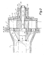
- a rotary fluid machine according to the present invention shown in the drawing is a so-called vane pump adapted to pump a thick or viscous mass, such as coarsely comminuted meat, supplied to the pump by means of a worm conveyor 1 rotating in a stationary worm housing 2.
- the pump proper consists in a known manner of a pump housing 3, in which a housing chamber 4 is provided in a known manner, said housing chamber being limited outwardly by the inner wall 5 of the pump housing 3.
- the inner wall 5 is not rotationally symmetrical about an axis 6 extending centrally in the housing chamber 4.
- a rotor consisting of a rotor ring 7 with a number - in the example shown eight - of radially extending vane slots or channels 8, in which a corresponding number of slides or vanes a-h are slidingly supported in a substantially fluid-tight manner.
- the rotor 7,8,a-h is rotatably supported in the housing chamber 4 with the axis 6 as its axis of rotation.
- a stationary vane guide block 9 shaped with an outwardly facing guiding surface 10, in cross section differing from the cir-. cular shape.
- inlet ports 11 In the machine's end wall 12 lying to the left in Fig. 2 there are provided two inlet ports 11, two outlet ports 13 extending through the outer wall of the machine housing 3 and hence also through the inner wall 5, and.connecting the housing chamber 4 with two outlet pipes 14. As can be seen from Fig. 2, the inlet ports 11 connect the inside of the worm housing 2 to the housing chamber 4.
- the part of the housing chamber 4 situated outside the rotor ring 7 is divided by the vanes a-h into a corresponding number of working chambers ab,bc,...gh,ha.
- the guiding surface 10 on the vane guide block 9 will be held in contact with or in a quite short distance from the inner wall 5 of the machine housing 3, and the working chambers ab-ha will thus, due to the non--circular shape of the inner wall 5, in a known manner vary in volume and convey the pumping medium (not shown) from the inlet ports 11 to the outlet ports 13.
- the features of the pump shown in Fig. 1 and 2 described above are in all essentials part of the prior art.
- the pump shown in the drawing does, however, differ from known pumps of a similar type primarily in that the vane guide block 9 is not secured to the machine housing 3 or any part connected therewith, but is "floating" in the space within the rotor ring 7.
- an interaction takes place between the vane guide block 9 and the vanes a-h, as on the one hand the vane guide block 9 guides the vanes a-h in such a manner that at any moment they are in the correct position relative to the inner wall 5 of the machine housing 3, while on the other hand the vanes a-h, due to the sliding cooperation with the inner wall 5, maintain the vane guide block 9 in its correct position.
- a first condition for the attainment of this effect is that the guiding surface 10 in a radial section (and moreover in a known manner) differs from the circular shape; one could say "the more, the better”.
- a second condition is that there is a sufficient number of vanes a-h, as otherwise there could be a risk that there was not always a vane ready to exert the said counter-force.
- the exemplary embodiment with eight vanes a-h shown has been successivefully tried in practice, but the effect could also be attained with a smaller number of vanes, four being, however, to be regarded as the minimum.
- the vane guide block 9 unlike what is the case in previously known machines of this type - is not secured to the machine housing 3, the drawbacks previously associated with securing the vane guide block are avoided.
- This block has thus normally been secured to one of the end walls in the pump, the rotor ring having been secured to and extending cantilever-fashion from a flange secured to the drive shaft at the opposite end wall in the pump.
- the rotor ring is divided by the vane slots or channels into a number of segments, it can be realized that there is a limit to the load tolerated by such a pump, e.g. in the form of lumps in the pumped medium, such as pieces of bone in the meat mass supplied to the pump.
- This weakening of the rotor ring 7 is, however, avoided in the pump according to the present invention, as the rotor ring is secured at both ends to a flange, viz. with its end facing left in Fig. 2 to a first supporting flange 16, and at the opposite end to a second supporting flange 17, by which the segments of the rotor ring 7 lying between the vane slots or channels 8 are secured at both ends (the manner of securing them is not shown in the drawing, as any suitable securing means, such as screws or bolts, may be used for this purpose).
- the two supporting flanges 16 and 17 may be secured to a drive shaft, which may be continuous, in a suitable manner.
- the first supporting flange 16 is secured to a main shaft 18 also carrying the worm 1, while the second supporting flange 17 is secured to a tubular shaft 19 inserted on the main shaft 18.
- a through-going opening 20 is provided in the vane guide block 9.
- the opening 20 may be circular-cylindrical with such a diameter that the vane guide block 9 is rotatably supported on the main shaft 18 - or rather the opposite, as the guide block 9 is stationary, and the shaft 18 rotates.
- the opening 20 as shown, i.e. where it is so much larger than the main shaft 18, that there is a certain clearance between these two parts.
- the conditions stated above for maintaining the guide block 9 stationary are to be changed by substituting "tending to move” for "tending to turn” - a condition, which may require somewhat more for it to be met, but which already has been met in the construction with eight vanes shown in the drawing.
- the tubular shaft 19 and hence also the main shaft 18 at its extreme right-hand end are rotatably supported in a bearing housing 21, secured to the second end wall 22 of the machine housing 3, by means of bearing means 23 not shown in greater detail, but which may consist of a pair of ball bearings or roller bearings, e.g. conical bearings.
- the worm housing 2 and the pump housing 3 have mutually facing conical flanges 24 and 25 respectively, being held together in a known manner by a peripheral clamping ring 26 being held tight in the tangential direction and hence pressing the two flanges 24 and 25 against each other.
- the bearing housing 21 is rigidly connected to the worm housing 2 through the second end wall 22, the pump housing 3 proper, the flanges 24 and 25 and the clamping ring 26, whereas the other end (not shown) of the worm housing 2 in a known manner may be secured to that housing or filling hc pp er (not shown), in which the material to be delivered by the worm 1 is placed.
- the requisite bearing support forces for the worm conveyor 1 are transmitted to the bearing means 23, partly through the main shaft 18 and the tubular shaft 19 placed thereon, partly through the first supporting flange 16, the rotor ring 7 and the second supporting flange 17. This provides a stable support for both the worm conveyor 1 and the rotating parts of the pump.
- the rotor ring 7 Since the rotor ring 7 is secured at both ends, viz. with one end to the first supporting flange 16 and with the other end to the second supporting flange 17, the rotor ring 7 is able to guide or control each and every vane a-h effectively by means of the vane slots or channels 8, even when the vanes a-h are subjected to other forces than pumping forces; thus when pumping meat mass containing lumps of bone, these lumps may enter through the inlet ports 11 and be jammed between the vertical (as shown in Fig. 1) edges of these inlet ports and a nearby vane edge. In the extremely sturdy embodiment shown, these bone lumps will, however, only be "clipped off" without any damage to the vane in question.
- the pump shown in the drawing is intended for use in conveying meat mass or mincemeat. For this purpose it is necessary that it be possible to dismantle, clean and sterilize the pump without too much inconvenience.
- this can be attained by removing a holding nut 27 with its associated locking nut 28 screwed onto the end of the main shaft 18, and a washer 22 situated behind these nuts 27 and 28 and abutting against a bearing sleeve 30 belonging to the bearing means 23, and opening the clamping ring 26 and hence free the two conical flanges 24 and 25 from each other.
- the pump housing 3 with the bearing housing 21 and the second end wall 22 may be removed to the right in Fig.
- the various dismantling steps are repeated in the opposite direction and order.
- each segment in the rotor ring 7 may be secured to the first supporting flange 16, the second supporting flange 17 only being connected to the rotor ring 7 through axially releasable plug-and--socket joints (not shown) or the like. In this way it is made possible, after having removed the housing parts 21,22 and 3 to pull the tubular shaft 19 with the second supporting flange 17 free of the main shaft 18, after which the vane guide block 9 may be pulled out along the main shaft 18.
- the first supporting flange 16 with the segments of the rotor ring 7 may also be freed from a conical hub,31 secured to the worm 1 and/or the main shaft 18, to which hub 31 the first supporting flange 16 is secured, e.g. as indicated by means of screws 32.
- a conical hub,31 secured to the worm 1 and/or the main shaft 18, to which hub 31 the first supporting flange 16 is secured e.g. as indicated by means of screws 32.
- Other constructions are of course possible, depending on the requirements of each application.
- the present invention has been described with reference to an exemplary embodiment with radially sliding vanes or slides a-h for dividing the outer part of the pump housing chamber into a number of working chambers. It does, however, lie within the scope of the present invention to construct and/or situate the requisite means for dividing the pump housing chamber in other ways.
- vanes extending at a skew angle relative to the radial direction of the rotor ring 7, or instead of vanes to use cylindrical rollers, e.g. in an arrangement corresponding to the one disclosed in PCT patent application No. W083/00527 (publication number).
- the active parts of the pump may consist of a material suited for such operation, e.g. stainless steel.
- a material suited for such operation e.g. stainless steel.
- more easily workable materials e.g. bronze, aluminium alloys or synthetic resins or other plastic organic materials.
- the vane guide block 9 It is also possible - even for more demanding applications - to construct the vane guide block 9 from a more yielding material, such as polyamide (NYLON O ), polyurethane or the like, since the rather rough loads, to which the vanes are subjected during the "clipping-off" of lumps, will only be transmitted to the vane guide block 9 to a minor extent or not at all.
- a more yielding material such as polyamide (NYLON O ), polyurethane or the like
- the invention is not limited to the construction of the inner wall 5 of the pump housing 3 and the shaping of the guiding surface 10 on the vane guide block 9 depending thereon as shown.
- the attention is drawn to the construction disclosed in the German Offenle g ungsschrift No. 2.245.875, comprising an oval-shaped vane guide block 22 with straight sides and rounded ends.
Landscapes
- Engineering & Computer Science (AREA)
- Mechanical Engineering (AREA)
- General Engineering & Computer Science (AREA)
- Rotary Pumps (AREA)
- Hydraulic Motors (AREA)
- Other Liquid Machine Or Engine Such As Wave Power Use (AREA)
- Structures Of Non-Positive Displacement Pumps (AREA)
Priority Applications (1)
| Application Number | Priority Date | Filing Date | Title |
|---|---|---|---|
| AT85116386T ATE30759T1 (de) | 1984-12-21 | 1985-12-20 | Fluidumverdraengermaschine mit kreisenden arbeitskammern und periodisch veraenderlichem hubraum. |
Applications Claiming Priority (2)
| Application Number | Priority Date | Filing Date | Title |
|---|---|---|---|
| DK6226/84 | 1984-12-21 | ||
| DK622684A DK151493C (da) | 1984-12-21 | 1984-12-21 | Roterende fluidumfortraengningsmaskine med kredsende arbejdskamre af periodisk varierende rumfang |
Publications (2)
| Publication Number | Publication Date |
|---|---|
| EP0187357A1 true EP0187357A1 (de) | 1986-07-16 |
| EP0187357B1 EP0187357B1 (de) | 1987-11-11 |
Family
ID=8148164
Family Applications (1)
| Application Number | Title | Priority Date | Filing Date |
|---|---|---|---|
| EP85116386A Expired EP0187357B1 (de) | 1984-12-21 | 1985-12-20 | Fluidumverdrängermaschine mit kreisenden Arbeitskammern und periodisch veränderlichem Hubraum |
Country Status (5)
| Country | Link |
|---|---|
| US (1) | US4728272A (de) |
| EP (1) | EP0187357B1 (de) |
| AT (1) | ATE30759T1 (de) |
| DE (1) | DE3560957D1 (de) |
| DK (1) | DK151493C (de) |
Cited By (1)
| Publication number | Priority date | Publication date | Assignee | Title |
|---|---|---|---|---|
| GB2576834A (en) * | 2017-03-30 | 2020-03-04 | Hwm Water Ltd | Cloud Computing server interface |
Families Citing this family (4)
| Publication number | Priority date | Publication date | Assignee | Title |
|---|---|---|---|---|
| US6857863B1 (en) | 2003-12-18 | 2005-02-22 | Visteon Global Technologies, Inc. | Power steering pump |
| US9188005B2 (en) * | 2007-10-18 | 2015-11-17 | Standex International Corporation | Sliding vane pump with internal cam ring |
| KR101697148B1 (ko) * | 2016-03-04 | 2017-01-17 | 황광선 | 원심 흡입식 하이브리드 베인 유체기계 |
| CN109882410B (zh) * | 2019-04-12 | 2024-01-30 | 重庆工商大学 | 一种旋片电子抽气泵 |
Citations (8)
| Publication number | Priority date | Publication date | Assignee | Title |
|---|---|---|---|---|
| US1442150A (en) * | 1921-10-08 | 1923-01-16 | Charles W Hottmann | Stuffer |
| US1889822A (en) * | 1930-05-10 | 1932-12-06 | Kenneth S Clapp | Pump |
| US1974761A (en) * | 1931-05-18 | 1934-09-25 | Floyd F Vogel | Internal combustion rotary engine |
| FR1315068A (fr) * | 1961-11-09 | 1963-01-18 | Moteur à combustion interne à piston rotatif | |
| US3187679A (en) * | 1963-06-10 | 1965-06-08 | Scognamillo Frank | Rotary machine |
| FR1547556A (fr) * | 1967-05-06 | 1968-11-29 | Handtmann Metallguss Albert | Dispositif de transport pour masses pâteuses, travaillant à la façon d'une pompe cellulaire, en particulier pour machines de remplissage des boyaux dans la production de saucisses |
| US3473478A (en) * | 1967-11-09 | 1969-10-21 | Waukesha Foundry Co | Vane pump with annular elastomeric vane-projecting springs |
| US3909158A (en) * | 1973-11-16 | 1975-09-30 | William A Martin | Vane type fluid motor |
Family Cites Families (7)
| Publication number | Priority date | Publication date | Assignee | Title |
|---|---|---|---|---|
| US1811729A (en) * | 1926-04-22 | 1931-06-23 | Henry F Molkenbur | Rotary engine |
| US2099193A (en) * | 1935-11-20 | 1937-11-16 | Brightwell Curtis Francis | Motor or pump |
| US3059862A (en) * | 1958-05-16 | 1962-10-23 | Improved Machinery Inc | Coaxial breaker conveyor and feeder |
| DE2222324A1 (de) * | 1972-05-06 | 1973-11-22 | Lucas Industries Ltd | Hydraulik-lamellenpumpe oder -motor |
| DE2245875A1 (de) * | 1972-09-19 | 1974-04-04 | Lucas Industries Ltd | Rotationskolbenmaschine |
| FR2202543A5 (de) * | 1972-10-10 | 1974-05-03 | Egretier Jean Michel | |
| DE3130670A1 (de) * | 1981-08-03 | 1983-02-17 | Maschinenfabrik Spandau KG Geco-Pumpentechnik GmbH & Co, 1000 Berlin | Verdraengermaschine, insbesondere ringkolbenmaschine |
-
1984
- 1984-12-21 DK DK622684A patent/DK151493C/da active
-
1985
- 1985-12-13 US US06/808,813 patent/US4728272A/en not_active Expired - Lifetime
- 1985-12-20 DE DE8585116386T patent/DE3560957D1/de not_active Expired
- 1985-12-20 EP EP85116386A patent/EP0187357B1/de not_active Expired
- 1985-12-20 AT AT85116386T patent/ATE30759T1/de not_active IP Right Cessation
Patent Citations (8)
| Publication number | Priority date | Publication date | Assignee | Title |
|---|---|---|---|---|
| US1442150A (en) * | 1921-10-08 | 1923-01-16 | Charles W Hottmann | Stuffer |
| US1889822A (en) * | 1930-05-10 | 1932-12-06 | Kenneth S Clapp | Pump |
| US1974761A (en) * | 1931-05-18 | 1934-09-25 | Floyd F Vogel | Internal combustion rotary engine |
| FR1315068A (fr) * | 1961-11-09 | 1963-01-18 | Moteur à combustion interne à piston rotatif | |
| US3187679A (en) * | 1963-06-10 | 1965-06-08 | Scognamillo Frank | Rotary machine |
| FR1547556A (fr) * | 1967-05-06 | 1968-11-29 | Handtmann Metallguss Albert | Dispositif de transport pour masses pâteuses, travaillant à la façon d'une pompe cellulaire, en particulier pour machines de remplissage des boyaux dans la production de saucisses |
| US3473478A (en) * | 1967-11-09 | 1969-10-21 | Waukesha Foundry Co | Vane pump with annular elastomeric vane-projecting springs |
| US3909158A (en) * | 1973-11-16 | 1975-09-30 | William A Martin | Vane type fluid motor |
Cited By (2)
| Publication number | Priority date | Publication date | Assignee | Title |
|---|---|---|---|---|
| GB2576834A (en) * | 2017-03-30 | 2020-03-04 | Hwm Water Ltd | Cloud Computing server interface |
| GB2576834B (en) * | 2017-03-30 | 2022-07-13 | Hwm Water Ltd | Cloud Computing server interface |
Also Published As
| Publication number | Publication date |
|---|---|
| DK151493B (da) | 1987-12-07 |
| EP0187357B1 (de) | 1987-11-11 |
| US4728272A (en) | 1988-03-01 |
| ATE30759T1 (de) | 1987-11-15 |
| DK151493C (da) | 1988-05-30 |
| DE3560957D1 (en) | 1987-12-17 |
| DK622684D0 (da) | 1984-12-21 |
| DK622684A (da) | 1986-06-22 |
Similar Documents
| Publication | Publication Date | Title |
|---|---|---|
| US6053717A (en) | Rotary pump with wiper insert | |
| US5715976A (en) | Cartridge bearing assembly for volumetric feeder | |
| GB2074247A (en) | Rotary Positive-displacement Pumps | |
| EP0187357B1 (de) | Fluidumverdrängermaschine mit kreisenden Arbeitskammern und periodisch veränderlichem Hubraum | |
| US5395215A (en) | Supports for rotatable housing of liquid ring pumps | |
| EP0659237B1 (de) | Flügelzellenmaschine | |
| US4958992A (en) | Variable capacity swivelling vane pump | |
| CA2580385C (en) | Vane pump comprising a two-part stator | |
| US3895893A (en) | Rotary piston pump | |
| EP2535589A2 (de) | Schneidwerkspumpe | |
| WO1984001408A1 (en) | Double vane pump | |
| WO2008131846A1 (de) | Förderpumpe | |
| US7192264B2 (en) | Hyrdraulic motor | |
| AU6536094A (en) | Filling, fluid-transporting and pumping device | |
| EP3828419B1 (de) | Mehrstufige kreiselpumpe | |
| US4606505A (en) | Comminuting machine, especially for emulsifying or fine comminuting of meat products | |
| RU2056537C1 (ru) | Жидкостно-кольцевая машина | |
| GB2047807A (en) | Rotary positive-displacement fluid-machines | |
| US3240155A (en) | Helical rotary pumps | |
| DE3423276A1 (de) | Fluegelmotor oder -pumpe | |
| EP0196469B1 (de) | Brennstoffpumpe mit elektrischem Antrieb | |
| CA2116001A1 (en) | Pump or compressor unit | |
| RU2176554C2 (ru) | Устройство для измельчения | |
| RU2018718C1 (ru) | Вертикальный насосный агрегат | |
| WO2024144472A1 (en) | A new stator assembly configuration for progressive cavity pumps |
Legal Events
| Date | Code | Title | Description |
|---|---|---|---|
| PUAI | Public reference made under article 153(3) epc to a published international application that has entered the european phase |
Free format text: ORIGINAL CODE: 0009012 |
|
| AK | Designated contracting states |
Kind code of ref document: A1 Designated state(s): AT BE CH DE FR GB IT LI LU NL SE |
|
| 17P | Request for examination filed |
Effective date: 19860923 |
|
| EL | Fr: translation of claims filed | ||
| 17Q | First examination report despatched |
Effective date: 19870305 |
|
| GRAA | (expected) grant |
Free format text: ORIGINAL CODE: 0009210 |
|
| AK | Designated contracting states |
Kind code of ref document: B1 Designated state(s): AT BE CH DE FR GB IT LI LU NL SE |
|
| PG25 | Lapsed in a contracting state [announced via postgrant information from national office to epo] |
Ref country code: NL Effective date: 19871111 Ref country code: LI Effective date: 19871111 Ref country code: CH Effective date: 19871111 Ref country code: BE Effective date: 19871111 Ref country code: AT Effective date: 19871111 |
|
| REF | Corresponds to: |
Ref document number: 30759 Country of ref document: AT Date of ref document: 19871115 Kind code of ref document: T |
|
| REF | Corresponds to: |
Ref document number: 3560957 Country of ref document: DE Date of ref document: 19871217 |
|
| PG25 | Lapsed in a contracting state [announced via postgrant information from national office to epo] |
Ref country code: LU Free format text: LAPSE BECAUSE OF NON-PAYMENT OF DUE FEES Effective date: 19871231 |
|
| ET | Fr: translation filed | ||
| ITF | It: translation for a ep patent filed | ||
| REG | Reference to a national code |
Ref country code: CH Ref legal event code: PL |
|
| NLV1 | Nl: lapsed or annulled due to failure to fulfill the requirements of art. 29p and 29m of the patents act | ||
| PLBE | No opposition filed within time limit |
Free format text: ORIGINAL CODE: 0009261 |
|
| STAA | Information on the status of an ep patent application or granted ep patent |
Free format text: STATUS: NO OPPOSITION FILED WITHIN TIME LIMIT |
|
| 26N | No opposition filed | ||
| ITTA | It: last paid annual fee | ||
| EAL | Se: european patent in force in sweden |
Ref document number: 85116386.5 |
|
| PGFP | Annual fee paid to national office [announced via postgrant information from national office to epo] |
Ref country code: SE Payment date: 19981127 Year of fee payment: 14 |
|
| PG25 | Lapsed in a contracting state [announced via postgrant information from national office to epo] |
Ref country code: SE Free format text: LAPSE BECAUSE OF NON-PAYMENT OF DUE FEES Effective date: 19991221 |
|
| EUG | Se: european patent has lapsed |
Ref document number: 85116386.5 |
|
| REG | Reference to a national code |
Ref country code: GB Ref legal event code: 732E |
|
| REG | Reference to a national code |
Ref country code: FR Ref legal event code: TP |
|
| REG | Reference to a national code |
Ref country code: GB Ref legal event code: IF02 |
|
| REG | Reference to a national code |
Ref country code: FR Ref legal event code: TP |
|
| PGFP | Annual fee paid to national office [announced via postgrant information from national office to epo] |
Ref country code: FR Payment date: 20041116 Year of fee payment: 20 |
|
| PGFP | Annual fee paid to national office [announced via postgrant information from national office to epo] |
Ref country code: GB Payment date: 20041124 Year of fee payment: 20 |
|
| PGFP | Annual fee paid to national office [announced via postgrant information from national office to epo] |
Ref country code: DE Payment date: 20050128 Year of fee payment: 20 |
|
| PG25 | Lapsed in a contracting state [announced via postgrant information from national office to epo] |
Ref country code: GB Free format text: LAPSE BECAUSE OF EXPIRATION OF PROTECTION Effective date: 20051219 |
|
| REG | Reference to a national code |
Ref country code: GB Ref legal event code: PE20 |