EP0187365B1 - Lagervorrichtung für abzubremsende drehbare oder schwenkbare Teile - Google Patents
Lagervorrichtung für abzubremsende drehbare oder schwenkbare Teile Download PDFInfo
- Publication number
- EP0187365B1 EP0187365B1 EP85116442A EP85116442A EP0187365B1 EP 0187365 B1 EP0187365 B1 EP 0187365B1 EP 85116442 A EP85116442 A EP 85116442A EP 85116442 A EP85116442 A EP 85116442A EP 0187365 B1 EP0187365 B1 EP 0187365B1
- Authority
- EP
- European Patent Office
- Prior art keywords
- bearing
- support
- elastic means
- spigot
- housing sleeve
- Prior art date
- Legal status (The legal status is an assumption and is not a legal conclusion. Google has not performed a legal analysis and makes no representation as to the accuracy of the status listed.)
- Expired
Links
Images


Classifications
-
- B—PERFORMING OPERATIONS; TRANSPORTING
- B65—CONVEYING; PACKING; STORING; HANDLING THIN OR FILAMENTARY MATERIAL
- B65D—CONTAINERS FOR STORAGE OR TRANSPORT OF ARTICLES OR MATERIALS, e.g. BAGS, BARRELS, BOTTLES, BOXES, CANS, CARTONS, CRATES, DRUMS, JARS, TANKS, HOPPERS, FORWARDING CONTAINERS; ACCESSORIES, CLOSURES, OR FITTINGS THEREFOR; PACKAGING ELEMENTS; PACKAGES
- B65D90/00—Component parts, details or accessories for large containers
- B65D90/12—Supports
- B65D90/14—Legs, e.g. detachable
Definitions
- the invention relates to a bearing device for rotatable or pivotable parts, in particular a bearing device for a support strut which is pivotally attached to the support of an interchangeable container, the part to be braked being provided with a bearing pin which has a braking device.
- Swap bodies for combined transport in the form of a container or a conventional truck body serve to hold goods in transit.
- the advantage of swap bodies is, for example, that they can be removed from the truck for loading and unloading. This means that the truck can be used for other purposes during this time.
- the swap body stands on four supports that are folded down on the side of the swap body frame.
- a support strut is pivotally arranged on each support, which connects the support to the frame of the swap body.
- the support is released from its anchoring in the frame of the swap body and brought into the support position, there is a risk that the support strut located parallel to the support will fall and this can cause injuries to personnel.
- a disadvantage of this design is that the support can only be brought into the standing position by overcoming the spring force, so that if the support is improperly or carelessly operated, injuries can occur due to the automatic opening of the support.
- the invention is therefore based on the object of designing the suspension of the support strut such that when the support strut is moved into the standing position, a risk to personnel is avoided.
- the braking device consists of a stationary housing sleeve and a bearing journal arranged concentrically therein, the bearing journal being supported on the housing sleeve by elastic means.
- a bearing journal is provided, on which an eccentric is arranged which carries a sleeve which is supported by rubber-elastic means on a stationary housing sleeve which is arranged concentrically to the bearing journal.
- a friction element e.g. a friction segment
- the friction element rests on a friction disc, which is supported on a stationary housing sleeve with the aid of elastic means.
- the elastic means can be a rubber ring or a spring.
- the released support strut can only fall down slowly; in extreme cases it may even have to be pressed down.
- the braking effect on the pivoting movement of the support strut is essentially dependent on the eccentricity of the eccentric or on the frictional forces of the friction element and the modulus of elasticity of the rubber-elastic support or on the spring force of the spring.
- the bearing journal in both embodiments has a lubrication channel through which the respective friction surfaces are lubricated in order to counteract premature wear.
- This storage device can be used not only for the special case described above, but wherever it is a matter of slowly dropping a pivotable part.
- the support is designated 1 and the support strut 2.
- the support 1 is mounted in a holder 3 which is attached to the frame 4 of the swap body.
- the rotatably arranged support strut 2 is detachably fastened to the frame 4 of the swap body on the side of the support 1.
- 5 designates the bearing journal, at one end of which the support strut 2 is fastened.
- the bearing pin 5 is mounted in the housing sleeve 6, which is firmly connected to the support 1.
- the bearing pin 5 has an eccentric 8, which carries a sleeve 7, which is supported on the housing sleeve 6 via a rubber sleeve 9.
- the axis of rotation of the journal 5 is identical to the geometric center axis of the housing sleeve 6; it is therefore concentric with the housing sleeve. If the bearing pin is now rotated, the eccentric 8 grinds against the inner wall of the Along sleeve 7, whereby this is pressed outward in the region of the eccentric to the rubber sleeve 9.
- FIG. 5 shows the second embodiment, the bearing journal 10, which is mounted in the housing sleeve 11, having a friction element designed as a friction segment 10a (FIG. 6).
- This friction segment 10a presses against a friction disk 12, which is supported by elastic means 13a and 13b on the housing sleeve 11 in the axial direction of the bearing pin.
- the elastic means can be a spring 13a or a rubber ring 13b.
- the braking effect is thus dependent on the size of the preload with which the bearing pin 10 presses against the elastic means, and on the size of the surface of the friction segment and on the elastic modulus of the rubber of the rubber ring or on the spring force.
- the friction surfaces are lubricated; for this purpose, the journal 5 and 10 each have a lubrication channel 5a and 1 Ob.
Landscapes
- Engineering & Computer Science (AREA)
- Mechanical Engineering (AREA)
- Support Of The Bearing (AREA)
- Braking Arrangements (AREA)
- Sliding-Contact Bearings (AREA)
Description
- Die Erfindung betrifft eine Lagervorrichtung für drehbare oder schwenkbare Teile, insbesondere eine Lagervorrichtung für eine Stützstrebe, die schwenkbar an der Stütze eines Wechselbehälters befestigt ist, wobei der abzubremsende Teil mit einem Lagerzapfen versehen ist, der eine Bremsvorrichtung aufweist.
- Wechselbehälter für den kombinierten Verkehr in Form eines Containers oder eines üblichen LKW-Aufbaus dienen zur Aufnahme von Transportgut. Der Vorteil von Wechselbehältern besteht beispielsweise darin, dass diese zum Zwecke des Be- und Entladens vom LKW abmontiert werden können. Dadurch kann der LKW während dieser Zeit anderweitig benutzt werden.
- Der Wechselbehälter steht auf vier Stützen, die seitlich am Rahmen des Wechselbehälters abgeklappt werden.
- Um einen sicheren Stand des Wechselbehälters zu gewährleisten, ist an jeder Stütze eine Stützstrebe schwenkbar angeordnet, die die Stütze mit dem Rahmen des Wechselbehälters verbindet.
- Wird nun die Stütze zum Zwecke des Abstellens des Wechselbehälters aus ihrer Verankerung im Rahmen des Wechselbehälters gelöst und in Stützstellung gebracht, so besteht die Gefahr, dass die parallel zu der Stütze befindliche Stützstrebe herunterfällt und hierdurch Verletzungen beim Personal hervorgerufen werden können.
- Man hat daher bereits schon vorgeschlagen, eine bei Anhängerfahrzeugen vorgesehene Stütze aus der Ruhestellung in die Standstellung zu bringen und dabei eine Feder zu spannen, die um einen Schwenkbolzen angeordnet ist, wobei das eine Federende am feststehenden Teil und das andere Federende an der Stütze befestigt ist. Dabei ist der Schwenkbolzen als Reibungswiderstandselement ausgebildet. Bei dieser Vorrichtung muss die Stütze in der Standstellung verriegelt sein, damit sie nicht das Bestreben hat wegen der Federkraft die Ruhelage wieder einzunehmen. (USP 30 24 870)
- Nachteilig bei dieser Ausbildung ist, dass die Stütze nur gegen Überwindung der Federkraft in die Standstellung gebracht werden kann, so dass bei unsachgemässer oder unvorsichtiger Arbeitsweise doch durch automatisches Hochschnellen der Stütze Verletzungen eintreten können.
- Der Erfindung liegt daher die Aufgabe zugrunde, die Aufhängung der Stützstrebe so auszubilden, dass beim Verstellen der Stützstrebe in die Standstellung eine Gefährdung des Personals vermieden ist.
- Das wird erfindungsgemäss dadurch erreicht, dass die Bremsvorrichtung aus einer ortsfesten Gehäusehülse und einem konzentrisch darin angeordneten Lagerzapfen besteht, wobei der Lagerzapfen durch elastische Mittel an der Gehäusehülse abgestützt ist.
- Nach einer ersten Ausführungsform ist ein Lagerzapfen vorgesehen, auf dem ein Exzenter angeordnet ist, der eine Hülse trägt, welche durch gummielastische Mittel an einer ortsfesten Gehäusehülse abgestützt ist, die konzentrisch zum Lagerzapfen angeordnet ist.
- Nach einer anderen Ausführungsform ist auf der Stirnseite des Lagerzapfens ein Reibelement, z.B. ein Reibsegment, angeordnet, das mit Hilfe elastischer Mittel abgestützt ist. Hierbei liegt das Reibelement an einer Reibscheibe an, welche mit Hilfe elastischer Mittel an einer ortsfesten Gehäusehülse abgestützt ist. Die elastischen Mittel können hierbei ein Gummiring oder eine Feder sein.
- Durch jede der beiden Ausführungsformen ist somit erreicht, dass die gelöste Stützstrebe nur langsam herunterfallen kann; im Extremfall vielleicht sogar heruntergedrückt werden muss.
- Die Bremswirkung auf die Schwenkbewegung der Stützstrebe ist im wesentlichen abhängig von der Exzentrizität des Exzenters bzw. von den Reibkräften des Reibelementes und dem Elastizitätsmodul der gummielastischen Abstützung bzw. von der Federkraft der Feder.
- Nach einem weiteren Merkmal weist der Lagerzapfen bei beiden Ausführungsformen einen Schmierkanal auf, durch den die jeweiligen Reibflächen geschmiert werden, um so einem vorzeitigen Verschleiss entgegenzuwirken.
- Diese Lagervorrichtung ist nicht nur für den oben beschriebenen Spezialfall einsetzbar, sondern überall da, wo es darum geht, ein schwenkbares Teil langsam abfallen zu lassen.
- In der Zeichnung sind zwei beispielsweise Ausführungsformen dargestellt.
- Fig. 1 zeigt einen Wechselbehälter;
- Fig. 2 zeigt einen vergrösserten Ausschnitt aus Fig. 1, in dem die Stütze mit Stützstrebe dargestellt ist;
- Fig. 3 zeigt die eine Ausführungsform der erfindungsgemässen Vorrichtung im Schnitt;
- Fig. 4 zeigt einen Schnitt gemäss der Linie IV-IV in Fig. 3;
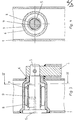
- Fig. 5 zeigt die zweite Ausführungsform der erfindungsgemässen Vorrichtung im Schnitt;
- Fig. 6 zeigt einen Schnitt gemäss der Linie VI-VI in Fig. 5.
- In Fig. 2 ist die Stütze mit 1 und die Stützstrebe mit 2 bezeichnet. Während des Transportes des Wechselbehälters lagert die Stütze 1 in einer Halterung 3, die am Rahmen 4 des Wechselbehälters befestigt ist. Um ein unbeabsichtigtes Abklappen der Stütze 1 bei einem selbständig stehenden Wechselbehälter zu verhindern, ist die drehbar angeordnete Stützstrebe 2 seitlich von der Stütze 1 am Rahmen 4 des Wechselbehälters lösbar befestigt.
- In Fig. 3 ist mit 5 der Lagerzapfen bezeichnet, an dessen einem Ende die Stützstrebe 2 befestigt ist. Der Lagerzapfen 5 ist in der Gehäusehülse 6 gelagert, die mit der Stütze 1 fest verbunden ist. Der Lagerzapfen 5 weist einen Exzenter 8 auf, der eine Hülse 7 trägt, die sich hierbei über eine Gummihülse 9 an der Gehäusehülse 6 abstützt. Hierbei ist die Drehachse des Lagerzapfens 5 identisch mit der geometrischen Mittelachse der Gehäusehülse 6; er liegt mithin konzentrisch zur Gehäusehülse. Wird nun der Lagerzapfen gedreht, so schleift der Exzenter 8 an der Innenwand der Hülse 7 entlang, wodurch diese im Bereich des Exzenters nach aussen an die Gummihülse 9 gedrückt wird. Da die Ausdehnung der Gummihülse 9 durch die Gehäusehülse 6 begrenzt ist, wird die Gummihülse demzufolge zusammengequetscht. Die Bremswirkung des Zapfens 5 tritt also dadurch ein, dass durch den Exzenter die Hülse 7 radial gegen die Gummihülse 9 gedrückt wird. Die Bremskraft ist hierbei also direkt abhängig von der Exzentrizität und von dem Elastizitätsmodul des Gummis (Fig. 4).
- Fig. 5 zeigt die zweite Ausführungsform, wobei der Lagerzapfen 10, der in der Gehäusehülse 11 gelagert ist, ein als Reibsegment 10a ausgebildetes Reibelement aufweist (Fig. 6). Dieses Reibsegment 10a drückt gegen eine Reibscheibe 12, die sich durch elastische Mittel 13a bzw. 13b an der Gehäusehülse 11 in axialer Richtung zum Lagerbolzen abstützt. Das elastische Mittel kann hierbei eine Feder 13a oder ein Gummiring 13b sein. Bei Drehung des Lagerzapfens 10 schleift das Reibsegment 10a unter Druck an der Reibscheibe 12.
- Die Bremswirkung ist hierbei also abhängig von der Grösse der Vorspannung, mit der der Lagerbolzen 10 gegen die elastischen Mittel drückt, und von der Grösse der Fläche des Reibsegmentes sowie von dem Elastizitätsmodul des Gummis des Gummiringes bzw. von der Federkraft.
- Um den an den Reibflächen auftretenden Verschleiss zu minimieren, werden die Reibflächen geschmiert; hierzu weisen der Lagerzapfen 5 bzw. 10 jeweils einen Schmierkanal 5a bzw. 1 Ob auf.
Claims (6)
Priority Applications (1)
| Application Number | Priority Date | Filing Date | Title |
|---|---|---|---|
| AT85116442T ATE44010T1 (de) | 1985-01-05 | 1985-12-21 | Lagervorrichtung fuer abzubremsende drehbare oder schwenkbare teile. |
Applications Claiming Priority (2)
| Application Number | Priority Date | Filing Date | Title |
|---|---|---|---|
| DE3500213 | 1985-01-05 | ||
| DE3500213A DE3500213C2 (de) | 1985-01-05 | 1985-01-05 | Gelenk für die drehbare Verbindung zweier gegeneinander verschwenkbarer Teile, wobei das Gelenk einen Drehwiderstand aufweist |
Publications (2)
| Publication Number | Publication Date |
|---|---|
| EP0187365A1 EP0187365A1 (de) | 1986-07-16 |
| EP0187365B1 true EP0187365B1 (de) | 1989-06-14 |
Family
ID=6259301
Family Applications (1)
| Application Number | Title | Priority Date | Filing Date |
|---|---|---|---|
| EP85116442A Expired EP0187365B1 (de) | 1985-01-05 | 1985-12-21 | Lagervorrichtung für abzubremsende drehbare oder schwenkbare Teile |
Country Status (3)
| Country | Link |
|---|---|
| EP (1) | EP0187365B1 (de) |
| AT (1) | ATE44010T1 (de) |
| DE (1) | DE3500213C2 (de) |
Families Citing this family (3)
| Publication number | Priority date | Publication date | Assignee | Title |
|---|---|---|---|---|
| DE8700792U1 (de) * | 1987-01-17 | 1987-03-05 | Gerd Schulz Fahrzeug- und Container-Technik, 2100 Hamburg | Schwenklagerung |
| DE4005140A1 (de) * | 1990-02-17 | 1991-08-22 | Gerd Schulz | Stuetze |
| FI98156C (fi) * | 1993-06-22 | 1997-04-25 | Sakari Pinomaeki | Nivelöintilaite |
Family Cites Families (7)
| Publication number | Priority date | Publication date | Assignee | Title |
|---|---|---|---|---|
| DE7535736U (de) * | 1976-03-11 | Gebr. Happich Gmbh, 5600 Wuppertal | Lager, insbesondere Schwenklager für eine Sonnenblende | |
| DE7111400U (de) * | 1971-08-12 | Ukaea | Einstellbares Reibungsgelenk | |
| US3024870A (en) * | 1958-07-30 | 1962-03-13 | Bassick Co | Truck locks |
| GB1059295A (en) * | 1961-03-22 | 1967-02-15 | Renault | Improvements relating to the mounting of road vehicle wheels |
| DE1856195U (de) * | 1962-05-15 | 1962-08-09 | Doria Werk | Gelenk fuer leuchten. |
| DE1886750U (de) * | 1963-10-25 | 1964-01-30 | Ignaz Vogel | Gelenk. |
| DE3407390A1 (de) * | 1984-02-29 | 1985-08-29 | Wihag Nutzfahrzeugtechnik Gmbh & Co Kg, 4800 Bielefeld | Winkelfoermiger stuetzfuss fuer wechselaufbauten von lastkraftwagen |
-
1985
- 1985-01-05 DE DE3500213A patent/DE3500213C2/de not_active Expired
- 1985-12-21 AT AT85116442T patent/ATE44010T1/de not_active IP Right Cessation
- 1985-12-21 EP EP85116442A patent/EP0187365B1/de not_active Expired
Also Published As
| Publication number | Publication date |
|---|---|
| DE3500213C2 (de) | 1986-12-11 |
| ATE44010T1 (de) | 1989-06-15 |
| EP0187365A1 (de) | 1986-07-16 |
| DE3500213A1 (de) | 1986-07-17 |
Similar Documents
| Publication | Publication Date | Title |
|---|---|---|
| DE69719923T2 (de) | Förderer | |
| EP1527993A1 (de) | Fördereinrichtung für einen Laderaum eines Flugzeugs | |
| DE10044370C1 (de) | Transportrolle | |
| EP0234423B1 (de) | Höhenverstellbare Stütze für Sattelanhänger | |
| EP0187365A1 (de) | Lagervorrichtung für abzubremsende drehbare oder schwenkbare Teile | |
| DE2619984A1 (de) | Schwimmsattelbremse | |
| DE3314404C2 (de) | Fahrkabinen-Kippsystem | |
| DE69807127T2 (de) | Schleifband Vorrichtung zum Bearbeiten einer cylindrischen Lageroberfläche eines Werkstückes | |
| DE8500154U1 (de) | Lagervorrichtung für abzubremsende drehbare oder schwenkbare Teile | |
| CH683127A5 (de) | Winkelsensor für den Winkel zwischen den Längsachsen eines Zugfahrzeugs und eines Anhängers. | |
| DE69200729T2 (de) | Schubkraftübertragungsvorrichtung an einen Bremsbetätiger. | |
| DE3308499A1 (de) | Bremszange fuer eine scheibenbremse | |
| EP0073897B1 (de) | Scheibenbremse mit wenigstens einem kreisscheibenförmigen Bremsbelag | |
| EP0241884A2 (de) | Austragevorrichtung für Schüttgut | |
| DE3509636C1 (de) | Sattelanhaenger | |
| EP0732297A2 (de) | Lagerkörper | |
| DE1965263B2 (de) | Dichtungseinrichtung an einer kontinuierlich arbeitenden entwaesserungspresse | |
| DE102004048218B4 (de) | Scheibenbremse für Schienenfahrzeuge | |
| DE4338767C2 (de) | Rollenantriebseinheit | |
| DD156928A5 (de) | Gleitendes gleichlauf-universalgelenk | |
| DE102017106793B4 (de) | Interieuranordnung für ein Kraftfahrzeug | |
| DE1780451B2 (de) | ||
| DE2329536A1 (de) | Hydraulisch betaetigter federspeicherzylinder, insbesondere federspeicherbremszylinder an kraftfahrzeugen | |
| DE2336604C3 (de) | Drehbar gelagerte Verbindung | |
| DE101613C (de) |
Legal Events
| Date | Code | Title | Description |
|---|---|---|---|
| PUAI | Public reference made under article 153(3) epc to a published international application that has entered the european phase |
Free format text: ORIGINAL CODE: 0009012 |
|
| 17P | Request for examination filed |
Effective date: 19860108 |
|
| AK | Designated contracting states |
Kind code of ref document: A1 Designated state(s): AT BE CH FR GB IT LI LU NL SE |
|
| RAP1 | Party data changed (applicant data changed or rights of an application transferred) |
Owner name: GERD SCHULZ KG FAHRZEUG- UND CONTAINER-TECHNIK |
|
| 17Q | First examination report despatched |
Effective date: 19871207 |
|
| GRAA | (expected) grant |
Free format text: ORIGINAL CODE: 0009210 |
|
| AK | Designated contracting states |
Kind code of ref document: B1 Designated state(s): AT BE CH FR GB IT LI LU NL SE |
|
| REF | Corresponds to: |
Ref document number: 44010 Country of ref document: AT Date of ref document: 19890615 Kind code of ref document: T |
|
| GBT | Gb: translation of ep patent filed (gb section 77(6)(a)/1977) | ||
| ET | Fr: translation filed | ||
| ITF | It: translation for a ep patent filed | ||
| PG25 | Lapsed in a contracting state [announced via postgrant information from national office to epo] |
Ref country code: LU Free format text: LAPSE BECAUSE OF NON-PAYMENT OF DUE FEES Effective date: 19891231 |
|
| PLBE | No opposition filed within time limit |
Free format text: ORIGINAL CODE: 0009261 |
|
| STAA | Information on the status of an ep patent application or granted ep patent |
Free format text: STATUS: NO OPPOSITION FILED WITHIN TIME LIMIT |
|
| 26N | No opposition filed | ||
| PGFP | Annual fee paid to national office [announced via postgrant information from national office to epo] |
Ref country code: FR Payment date: 19900627 Year of fee payment: 5 |
|
| PGFP | Annual fee paid to national office [announced via postgrant information from national office to epo] |
Ref country code: SE Payment date: 19901017 Year of fee payment: 6 |
|
| PGFP | Annual fee paid to national office [announced via postgrant information from national office to epo] |
Ref country code: CH Payment date: 19901025 Year of fee payment: 6 |
|
| PGFP | Annual fee paid to national office [announced via postgrant information from national office to epo] |
Ref country code: BE Payment date: 19901031 Year of fee payment: 6 |
|
| PGFP | Annual fee paid to national office [announced via postgrant information from national office to epo] |
Ref country code: AT Payment date: 19901126 Year of fee payment: 6 |
|
| PGFP | Annual fee paid to national office [announced via postgrant information from national office to epo] |
Ref country code: GB Payment date: 19901214 Year of fee payment: 6 |
|
| PGFP | Annual fee paid to national office [announced via postgrant information from national office to epo] |
Ref country code: LU Payment date: 19901221 Year of fee payment: 6 |
|
| ITTA | It: last paid annual fee | ||
| PGFP | Annual fee paid to national office [announced via postgrant information from national office to epo] |
Ref country code: NL Payment date: 19901231 Year of fee payment: 6 |
|
| EPTA | Lu: last paid annual fee | ||
| PG25 | Lapsed in a contracting state [announced via postgrant information from national office to epo] |
Ref country code: FR Effective date: 19910830 |
|
| REG | Reference to a national code |
Ref country code: FR Ref legal event code: ST |
|
| PG25 | Lapsed in a contracting state [announced via postgrant information from national office to epo] |
Ref country code: GB Effective date: 19911221 Ref country code: AT Effective date: 19911221 |
|
| PG25 | Lapsed in a contracting state [announced via postgrant information from national office to epo] |
Ref country code: SE Effective date: 19911222 |
|
| PG25 | Lapsed in a contracting state [announced via postgrant information from national office to epo] |
Ref country code: LI Effective date: 19911231 Ref country code: CH Effective date: 19911231 Ref country code: BE Effective date: 19911231 |
|
| BERE | Be: lapsed |
Owner name: GERD SCHULZ K.G. FAHRZEUG-UND CONTAINER-TECHNIK Effective date: 19911231 |
|
| PG25 | Lapsed in a contracting state [announced via postgrant information from national office to epo] |
Ref country code: NL Effective date: 19920701 |
|
| NLV4 | Nl: lapsed or anulled due to non-payment of the annual fee | ||
| GBPC | Gb: european patent ceased through non-payment of renewal fee | ||
| REG | Reference to a national code |
Ref country code: CH Ref legal event code: PL |
|
| EUG | Se: european patent has lapsed |
Ref document number: 85116442.6 Effective date: 19920704 |