EP0187389A2 - Apparat zur Gewinnung von Bildinformationen durch magnetische Kernresonanzsignale - Google Patents
Apparat zur Gewinnung von Bildinformationen durch magnetische Kernresonanzsignale Download PDFInfo
- Publication number
- EP0187389A2 EP0187389A2 EP85116651A EP85116651A EP0187389A2 EP 0187389 A2 EP0187389 A2 EP 0187389A2 EP 85116651 A EP85116651 A EP 85116651A EP 85116651 A EP85116651 A EP 85116651A EP 0187389 A2 EP0187389 A2 EP 0187389A2
- Authority
- EP
- European Patent Office
- Prior art keywords
- coil
- magnetic field
- magnet
- examinee
- static
- Prior art date
- Legal status (The legal status is an assumption and is not a legal conclusion. Google has not performed a legal analysis and makes no representation as to the accuracy of the status listed.)
- Granted
Links
Images







Classifications
-
- G—PHYSICS
- G01—MEASURING; TESTING
- G01R—MEASURING ELECTRIC VARIABLES; MEASURING MAGNETIC VARIABLES
- G01R33/00—Arrangements or instruments for measuring magnetic variables
- G01R33/20—Arrangements or instruments for measuring magnetic variables involving magnetic resonance
- G01R33/28—Details of apparatus provided for in groups G01R33/44 - G01R33/64
-
- G—PHYSICS
- G01—MEASURING; TESTING
- G01R—MEASURING ELECTRIC VARIABLES; MEASURING MAGNETIC VARIABLES
- G01R33/00—Arrangements or instruments for measuring magnetic variables
- G01R33/20—Arrangements or instruments for measuring magnetic variables involving magnetic resonance
- G01R33/28—Details of apparatus provided for in groups G01R33/44 - G01R33/64
- G01R33/32—Excitation or detection systems, e.g. using radio frequency signals
- G01R33/34—Constructional details, e.g. resonators, specially adapted to MR
- G01R33/341—Constructional details, e.g. resonators, specially adapted to MR comprising surface coils
-
- G—PHYSICS
- G01—MEASURING; TESTING
- G01R—MEASURING ELECTRIC VARIABLES; MEASURING MAGNETIC VARIABLES
- G01R33/00—Arrangements or instruments for measuring magnetic variables
- G01R33/20—Arrangements or instruments for measuring magnetic variables involving magnetic resonance
- G01R33/28—Details of apparatus provided for in groups G01R33/44 - G01R33/64
- G01R33/38—Systems for generation, homogenisation or stabilisation of the main or gradient magnetic field
- G01R33/383—Systems for generation, homogenisation or stabilisation of the main or gradient magnetic field using permanent magnets
-
- G—PHYSICS
- G01—MEASURING; TESTING
- G01R—MEASURING ELECTRIC VARIABLES; MEASURING MAGNETIC VARIABLES
- G01R33/00—Arrangements or instruments for measuring magnetic variables
- G01R33/20—Arrangements or instruments for measuring magnetic variables involving magnetic resonance
- G01R33/28—Details of apparatus provided for in groups G01R33/44 - G01R33/64
- G01R33/38—Systems for generation, homogenisation or stabilisation of the main or gradient magnetic field
- G01R33/387—Compensation of inhomogeneities
- G01R33/3873—Compensation of inhomogeneities using ferromagnetic bodies ; Passive shimming
Definitions
- the present invention relates to-an apparatus for obtaining image information from a living body under examination through use of a nuclear magnetic resonance signal, and more particularly to the relative arrangement of its static magnetic field and radio-frequency magnetic field and the examinee's body.
- NMR-CT apparatus nuclear magnetic resonance-CT apparatus
- the NMR phenomenon occurs through such a mechanism as follows:
- atomic nuclei When placed in a static magnetic field, atomic nuclei resonate with a component of a radio-frequency magnetic field (hereinafter referred to as R F magnetic field or simply as RF field) of a specified frequency proportional to the intensity of the static magnetic field (which may hereinafter be referred to as static field which is perpendicular to that component, and precess about an axis in the direction of application of the static magnetic field at the above frequency (a resonance frequency).
- R F magnetic field radio-frequency magnetic field
- RF field radio-frequency magnetic field
- a specified frequency proportional to the intensity of the static magnetic field
- static field which is perpendicular to that component
- a magnetic field which has the same direction as the static magnetic field and whose intensity varies along a specified direction that is, a so-called gradient magnetic field (which may hereinafter be referred to as gradient field)
- gradient field which may hereinafter be referred to as gradient field
- nuclear spins atomic nuclei
- Fig. 1 illustrates in block form specific constituents of the NMR-CT apparatus.
- a static magnetic field generating magnet 11 applies a static magnetic field to a living body (not shown) and a gradient magnetic field generating coil 12 applies thereto a gradient magnetic field.
- the gradient field is identical in direction with the static field and its intensity is graded in three directions which usually intersect one another at right angles. This field arrangement permits discrimination of spatial information of the body.
- RF power in the resonance frequency band is provided from a transmitter 13 via an automatic transmission/reception switching circuit 14 to an RF coil 15.
- An RF magnetic field which is perpendicular to the static field, is applied from the RF coil 15 to the body.
- the resulting NMR signal from the body is received by the RF coil 15, from which it is supplied to a receiver 17 via the automatic transmission/ reception switching circuit 14 and a receiving coil select circuit 16.
- the NMR signal is converted by an A/D converter 18 into a digital signal.
- the digital signal is provided to a computer 19, in which it is subjected to a calculation process for image reconstruction, etc., and its results are displayed as an image on a display 20.
- the static field generating magnet 11 is excited by a static field generating means lla and the gradient field generating coil 12 by a gradient field generating means 12a.
- the static field direction When the direction of the magnetic fields emanating from the static field generating magnet 11 and the gradient field generating coil 12 (which direction will hereinafter be referred to as the static field direction) perpendicularly intersect the direction of the RF magnetic field (hereinafter referred to as the RF direction) from the RF coil 15, the application of the RF field and the detection of the NMR signal can be achieved with the highest efficiency.
- the NMR-CT apparatus satisfying above conditions are roughly divided into two groups in terms of the magnetic field generating structure. In a group 1 the static field direction and the direction in which a human body is taken into and out of the static field are perpendicular to each other, whereas in a group 2 the both directions are parallel to each other.
- a solenoid coil is often used as the RF coil in the case of the group 1, and in the case of the group 2 a saddle-shaped coil is usually employed.
- the RF coil for detecting the NMR signal is naturally one of important components which determine the SN ratio of the NMR-CT.
- the solenoid coil is about three times higher than the saddle-shaped coil in RF sensitivity.
- an RF coil commonly referred to as a surface coil is often used according to the region of examination (limited t Q regions near the skin surface).
- the surface coil has a spiral configuration, as shown in Fig. 2A, which is substantially flat and small in the number of turns.
- the RF field emanating from the surface coil is perpendicular to the coil plane.
- the surface coil is designed so that the SN ratio of the NMR signal from the region of examination may be maximum taking into account an area of the region of examination. In practical use the surface coil is applied to the skin surface corresponding to the region of examination with the coil plane held in parallel to the skin surface.
- a surface coil 21 is connected to the receiver 17 via the receiving coil select circuit 16 which switches between the surface coil 21 and the solenoid coil 15 as required. That is, the RF field is applied to the body from the solenoid coil 15 and the NMR signal from the body is received by the solenoid coil 15 and the surface coil 21, and selectively provided via the receiving coil select circuit 16 to the receiver 17.
- the receiving coil select circuit 16 selectively connects the automatic transmission/reception switching circuit 14 and the surface coil 21 to the receiver 17.- It is possible to arrange such that the solenoid coil 15 and the surface coil 21 are selectively connected to the automatic transmission/ reception switching circuit 14, the receiver 17 is connected directly to the automatic transmission/reception switching circuit 14. In this case, if desired, the surface coil 21 may be used both for generation of the RF field and reception of NMR signal.
- the surface coil Chief regions of examination through use of.the surface coil are, in the case of the human body, an eye, the breast, the backbone, the heart, the liver, the kidney and so forth.
- the human body has an elliptic cross-section in a transverse direction in which the breadth of the body is larger than the thickness of the body, that vertical dimensions of the body are far larger than the dimensions of the transverse cross-section and that the examinee usually lies. on his back during examination, it is highly desirable that the surface coil be disposed with its RF direction held vertical.
- the static field direction must be made horizontal so as to meet the aforementioned requirement that the static field direction and the RF direction be perpendicular to each other.
- the static field direction is parallel to the longitudinal axis of the lying human body, and hence is originally horizontal, but in the magnet system of the group 1 the static field direction is conventionally limited specifically to the direction perpendicular to the lying human body.
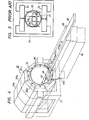
- the static field generating means employing permanent magnets is such as shown in Fig. 3 in which different magnetic poles of the permanent magnets 22 and 23 are disposed opposite but spaced apart in the vertical direction and are interconnected via a magnetic yoke 24, setting up a vertical static field 25 between the opposing faces of the magnets 22 and 23.
- a solenoid coil 26 for the RF magnetic field is disposed in the static magnetic field 25.
- the axis of the solenoid coil 26 is extended in a horizontal direction and is perpendicular to-the static field 25.
- a deck 27 is horizontally disposed in a manner to be slidable in parallel with the axis of the solenoid coil 26 and an examinee 28 lies on the deck 27.
- the magnet system of the group 1 presents the problem that the surface coil cannot be used with its RF direction held vertical.
- An object of the present invention is to provide an NMR-CT apparatus which has the magnet system of the group 1 capable of using the solenoid coil about three times higher in the RF sensitivity than the saddle-shaped coil and which allows to use the surface coil of the vertical RF direction which is effective for examination of the internal organs or regions near the skin surface.
- the NMR-CT apparatus of the present invention has an arrangement which makes the static field direction horizontal and permits an access to the examinee's body in a direction perpendicular to the static field direction in this horizontal plane.
- the solenoid coil for generating the RF magnetic field is disposed with its axis held perpendicular to the static field direction but parallel to the horizontal direction.
- the examinee's body is brought into and out of the solenoid coil. Furthermore, provision is made for selectively connect the surface coil and the solenoid coil to the receiver.
- High-frequency pulses are applied to the solenoid coil or surface coil and an NMR signal is received by either one of the solenoid coil or surface coil and is supplied to the receiver, and then processed to obtain spatial distribution information, which is displayed as an image.
- the NMR signals from both the solenoid coil and surface coil may be supplied to the receiver.
- Means for generating the static magnetic field may preferably be formed by a plurality of magnet rings each of which comprises a plurality of permanent magnet blocks disposed in the form of a ring so that they provide . magnetic fields of substantially one direction within the magnet ring.
- the magnet rings are arranged side by side with their axes held in agreement with one another to extend in the horizontal direction. It is preferable to provide means for adjusting the position of each magnet block in the radial direction of each magnet ring, in the skew direction about that radial direction and in the tangential direction.
- FIGs. 4 to 7 illustrate an embodiment of the present invention.
- a static magnetic field generating device 32 is mounted on a mount 31.
- the static field is generated by a permanent magnet assembly through use of a technique disclosed in United States Patent No. 4, 498,048.
- three magnet rings 34a, 34b and 34c each composed of eight anisotropic permanent magnet blocks 33 arranged in the form of a ring, are coaxially aligned in the horizontal direction.
- the magnet blocks of each magnet ring are respectively magnetized in such directions as indicated by the arrows 35, developing a horizontal static magnetic field 36 inside the magnet ring.
- the magnet rings 34a, 34b and 34c are respectively secured to magnet support frame means 37a, 37b and 37c outside thereof and the magnet support frame means are fixedly mounted on the mount 31, as shown in Fig. 4.
- a bobbin 38 is disposed inside the magnet rings 34a, 34b and 34c coaxially therewith and a gradient field coil 39 is wound on the bobbin 38.
- -Both ends of the bobbin 38 project outwardly of the magnet rings 34a and 34c and are held on support bases 41a and 41b.
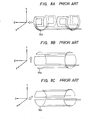
- the gradient field coil 39 is comprised of a coil 39z for generating a Z-direction gradient field the intensity of which varies in a direction parallel to the axis of the bobbin 38, a coil 39y for generating a Y-direction gradient field the intensity of which varies in the Y-direction and a coil 39x for generating an X-direction field the intensity of which varies in the X-direction.
- the coil 39z is wound, for instance, in such a form as shown in Fig. 8A and its particulars are disclosed, for example, in Japanese Patent Application Laid Open No. 15749/84.
- the coils 39y and 39x are wound on the coil 39z, for example, in such forms as shown in Figs. 8B and 8C, respectively. Their winding configurations are described in detail in Japanese Patent Application Laid Open No. 57140/80. These gradient fields are all produced in the Z-direction.
- a rail 42 is fixedly mounted on the bottom of the bobbin 38 inside thereof to extend in the Z-direction.
- a slot 42S is cut in the rail 42 to extend from one end to the center thereof in the Z-direction and a solenoid coil 43 is disposed inside the bobbin 38, passing through the slot 42S.
- the solenoid coil 43 is wound on a bobbin 44 with its axis held in parallel to the Z-axis and is positioned corresponding to the magnet ring 34b.
- the bobbin 44 is detachably secured to the rail 42.
- a bed 45 with its top surface almost flash with that of the rail 42.
- a carriage 46 for carrying an examinee 47 is mounted on the.bed 45 in a manner to be slidable into and out of the bobbin 38.
- rollers 48 are attached to the rail 42 and the bed 45 as required.
- the examinee 47 is brought into and out of the bobbin 38 in a direction perpendicular to the horizontal static magnetic field 36 as shown in Fig. 7 so that the static field 36 is applied perpendicularly to the longitudinal axis of the examinee's body.
- a recess 51 is made in the carriage 46 for receiving therein a surface coil 49, as required, which allows easy positioning of the examinee's body relative to the surface coil 49 before inserting the body into the bobbin 38.
- Fig. 9 shows a practical arrangement of the static field generating device 32, wherein each of the magnet support frame means 37a, 37b, 37c is formed by a pair of parallel ring plates 59 and 61 and each magnet block 33 is mounted to the parallel ring plates via position adjusting means as will be explained hereinafter.
- the magnet blocks are each produced by binding a number of small magnet pieces in combination.
- the magnet support frame means 37a, 37b and 37c are loosely threaded with common coupling rods 53 and nuts 54 are threadedly engaged with the coupling rods 53 to clamp each support frame means on both sides thereof, fixing it in position.
- tangential/skew adjusting means 87, 88 are fixedly mounted to each pair of the ring plates on both outer side thereof in a corresponding relation to the respective magnet blocks of each magnet ring.
- the radial adjusting means 75 for each magnet block 33 of the inner magnet ring 34b is formed as a wedge type adjusting mechanism.
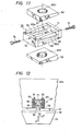
- Figs. 10A, 10B and 11 show an example of the wedge type radial adjustment mechanism.
- An engaging ring 57 is mounted on a back plate 56 of the magnet block 33 and a rod 58 is engaged at one end thereof with the engaging, ring 57 through its flange 58a so that the rod 58 is rotatably mounted on the magnet block 33.
- the pair of opposed ring plates 59b and 61b are interconnected through a pair of wedge plates 62 and 63 at the position of each magnet block 33.
- the abovementioned rod 58 is received in holes 62H, 63H made in the wedge plates 62 and 63.
- the rod 58 has an engaging flange 64 formed integrally therewith between the wedge plates 62 and 63. As shown in Fig.
- a pair of upper wedge bars 65, 66 are fixedly attached at thicker ends thereof to upper side corners of a coupling plate 71 and a pair of lower wedge bars 67, 68 are similarly fixed to lower side corners of a coupling plate 72.
- the thinner ends of the wedge bars 65, 66 and 67, 68 are connected to the upper and lower ends of the opposite coupling plates 72 and 71, respectively, so as to form a wedge frame 70 having rectangular guide apertures 6Ga and 6Gb defined between the wedge bars 65 and 67 and between the wedge bars 66 and 68.
- the wedge frame 70 is slidably interposed' between the upper and lower wedge plates 62 and 63.
- the rod 58 is engaged with the wedge frame 70 to extend through between the wedge bars 65 and 66 and between the wedge bars 66 and 68, with radially opposite parts of the engaging flange 64 being slidably disposed in the guide apertures 6Ga, 6Gb.
- the coupling plates 71 and 72 have made therein threaded holes, in which bolts 73 and 74 are threadedly received with their tips abutted against the peripheral surface of the engaging flange 64. In this way, a radially adjusting wedge mechanism 75 is formed.
- the wedge frame 70 is pulled out in a direction in which the coupling plate 71 moves away from a center axis of the rod 58. Since the wedge plates 62 and 63 are fixed to the ring plates 59b, 61b, the engaging flange 64 is pushed up to move the rod 58 and the magnet block 33 in a direction opposite from the arrow S, that is, radially of the magnet ring 34b .away from its axis.
- the radially adjusting wedge mechanism permits fine control but is somewhat complex in structure.
- the outer magnet rings 34a and 34c do not call for such fine control as is needed for the magnet ring 34b sandwiched therebetween. That is, adjustment of the magnet ring 34b, even if slight, will exert a great influence. From this viewpoint, only a simple bolt type adjustment mechanism 89 is employed in place of the radial adjusting wedge mechanism 75 for each magnet block in the outer magnet rings 34a, 34c as shown in Fig. 9.
- the bolt type adjustment mechanism 89 has an arrangement in which a threaded rod 92 is screwed into a hole made in a disk 93 mounted on coupling plate 91 joining the pair of ring plates (59a, 61a; 59c, 61c) and are rotatably connected at one end to the magnet blocks 33. By turning the threaded rods 92, the magnet blocks 33 are moved back and forth radially of the magnet ring.
- the tangential/skew adjusting means 87, 88 is provided in association with each magnet block 33 on outer sides of each pair ring plates 59, 61 as shown in Fig. 9 and will be explained hereinafter with respect to Figs. 10B and 12.
- On the outside of the ring plate 61 opposite from the rod 58 is fixedly mounted a wedge case 76 above the back plate 56 of the magnet block 33, as depicted in Figs. 10B and 12.
- the wedge case 76 is open on the side of the magnet block 33 and has disposed therein an engaging wedge piece 77. In the wedge case 76 wedges 78 and 79 are pressed into between- side panels of the case 76 and the engaging wedge piece 77.
- Bolts 81 and 82 are threadedly received by the wedges 78 and 79 through holes made in an upper end face of the wedge case 76 in alignment with the wedges 78 and 79, respectively.
- the bolts 81 and 82 are fixed to the wedge case 76 by means of nuts 83 and 84.
- An engaging hole 85 is made in the larger end face of the engaging wedge piece 77 adjacent the back plate 56 and a pin planted on the back plate 56 is slidably received in the engaging hole 85.
- the tangential/skew adjusting means 87 is constructed as a wedge mechanism.
- the tangential/skew adjusting means 88 is constructed as a wedge mechanism.
- the wedge mechanism 88 works in a manner similar to that of the wedge mechanism 87. Accordingly, by concurrent adjustment of the both wedge mechanisms 87 and 88 to displace the magnet block 33 in the direction of the arrow a or in the opposite direction, it is possible to adjust the position of the magnet block 33 in the tangential direction of the magnet ring 34b. Furthermore, by adjusting the both wedge mechanisms 87 and 88 in the opposite directions, the magnet block 33 can be skewed about the rod 58.
- the magnet rings. 34a, 34b'and 34c were each comprised of eight magnet blocks 33, each of which was produced by binding a number of rare earth iron magnets (measuring 50 x 30 x 20 mm) of Nd-Fe-B series whose residual magnetism was in the range of 12.0 to 12.6 K gausses, a homogeneous magnetic field with a difference between maximum and minimum field intensities held within 30 ppm was obtained inside a cylindrical plane with a radius of 175 mm from the center of each magnet ring.
- a homogeneous magnetic field can be obtained in a wide space. In particular, sufficiently high resolution can be obtained even if magnetic fields are applied to the examinee's body horizontally along the longer diameter of the elliptical cross-section of the body.
- the examinee lying on his back or stomach on the carriage 46 is brought into and out of the bobbin 38, that is, along the axial direction of the solenoid coil 43 for generating the RF magnetic field. Accordingly, an NMR signal of high SN ratio can be obtained through utilization of the solenoid coil 43, so that a tomographic image of the examinee 47 can be produced. It is also possible to exchange the solenoid coil 43 with another one of a diameter corresponding to the size of a particular part of the examinee's body such as the head, the trunk or the like. When it is desired to limit the examination to a small specified region of the examinee's body, the surface coil 49 of a solenoid type such as shown in Fig.
- the shape of the surface coil can be selected in accordance with the surface configuration of a particular region of examination. For example, in the case of examining the breast, such a spiral surface coil of a cone-shape as shown in Fig. 2C may b& used.
- the surface coil 49 - can be disposed with its RF direction held vertically, permitting effective examination of various parts of the examinee's body.
- S/N of the received signal can be further improved by obtaining NMR signals from both the solenoid coil 43 and the surface coil 49 and supplying them to the receiver 17.
- the static field generating means is not limited specifically to the magnet device previously described but may also be such, for example, as shown in Fig. 13.
- different magnetic poles of permanent magnets 101 and 102 are disposed in opposing relation so that the horizontal static magnetic field 36 is set up therebetween.
- the RF field generating solenoid coil 43 In the static field 36 is disposed the RF field generating solenoid coil 43, together with a gradient field generating coil though not shown.
- the axis of the solenoid coil 43 is horizontal and perpendicularly crosses the direction of the static field 36.
- the carriage 46 is disposed so that it is slid into and out of the solenoid coil 43 in parallel to its axis. That is, the examinee is brought into and out of the static field perpendicularly thereto from the horizontal direction.
- the magnets 101 and 102 are interconnected via a magnetic yoke 103. That is, the opposed magnets 101 and 102 are disposed on the left and right of the examinee's body 47 so that the static field 36 is horizontally directed and is perpendicular to the longitudinal axis of the examinee's body 47.
- the solenoid coil 43 can be employed for the purpose of obtaining a uniform tomographic image of the entire region of the head or the body of the examinee 47.
- the surface coil 49 under or on the examinee's body 47.
- Fig. 14 In the case of using resistive magnets, an arrangement such as depicted in Fig. 14 is employed, in which static field coils 104 and 105 are arranged horizontally in opposing relation, so that their axes are horizontal.
- the RF field generating solenoid coil 43 and the carriage 46 are disposed between the static field coils 104 and 105.
- the static field coils 104 and 105 are excited by a power supply 106.
- the gradient field generating coil is also provided, though not shown.
- a solenoid coil of high sensitivity is used and a surface coil can be employed with its RF direction held vertical. Accordingly, it is possible to use an RF coil most suitable for a particular region for examination at all times.
Landscapes
- Physics & Mathematics (AREA)
- Condensed Matter Physics & Semiconductors (AREA)
- General Physics & Mathematics (AREA)
- Magnetic Resonance Imaging Apparatus (AREA)
Applications Claiming Priority (2)
| Application Number | Priority Date | Filing Date | Title |
|---|---|---|---|
| JP201444/84 | 1984-12-30 | ||
| JP1984201444U JPS61115958U (de) | 1984-12-30 | 1984-12-30 |
Publications (3)
| Publication Number | Publication Date |
|---|---|
| EP0187389A2 true EP0187389A2 (de) | 1986-07-16 |
| EP0187389A3 EP0187389A3 (en) | 1987-05-27 |
| EP0187389B1 EP0187389B1 (de) | 1989-05-31 |
Family
ID=16441186
Family Applications (1)
| Application Number | Title | Priority Date | Filing Date |
|---|---|---|---|
| EP85116651A Expired EP0187389B1 (de) | 1984-12-30 | 1985-12-30 | Apparat zur Gewinnung von Bildinformationen durch magnetische Kernresonanzsignale |
Country Status (4)
| Country | Link |
|---|---|
| US (1) | US4727327A (de) |
| EP (1) | EP0187389B1 (de) |
| JP (1) | JPS61115958U (de) |
| DE (1) | DE3570757D1 (de) |
Cited By (12)
| Publication number | Priority date | Publication date | Assignee | Title |
|---|---|---|---|---|
| EP0268083A1 (de) * | 1986-10-28 | 1988-05-25 | Siemens Aktiengesellschaft | Oberflächenresonator zur Kernspintomographie |
| EP0271123A1 (de) * | 1986-11-07 | 1988-06-15 | Koninklijke Philips Electronics N.V. | Verfahren und Vorrichtung zur Bestimmung der durch Oberflächenspulen erzeugten und korrigierten Bilder mittels magnetischer Kernresonanz |
| DE3743105A1 (de) * | 1986-12-19 | 1988-07-07 | Toshiba Kawasaki Kk | Sende/empfangssystem fuer magnetresonanz-abbildungssystem |
| EP0228154A3 (en) * | 1985-12-27 | 1988-07-20 | Sumitomo Special Metals Co., Ltd. | Magnetic field generating device for nmr-ct |
| FR2612641A1 (fr) * | 1987-03-19 | 1988-09-23 | Oreal | Appareil pour l'examen d'un corps par resonance magnetique nucleaire par des methodes lentes et rapides, notamment pour l'examen de la couche superficielle de ce corps, dispositif pour creer un gradient de champ magnetique pour un tel appareil, et application a l'imagerie de la peau du corps humain |
| FR2623908A1 (fr) * | 1987-11-27 | 1989-06-02 | Thomson Cgr | Appareil d'imagerie par resonance magnetique nucleaire et antenne de reception pour un tel appareil |
| DE3907927A1 (de) * | 1989-03-11 | 1990-09-20 | Bruker Analytische Messtechnik | Magnetsystem |
| EP0373000A3 (de) * | 1988-12-09 | 1991-05-08 | Picker International Limited | Apparat mit magnetischer Resonanz |
| US5207224A (en) * | 1988-12-09 | 1993-05-04 | Picker International, Ltd. | Magnetic resonance apparatus |
| EP0577001A1 (de) * | 1992-06-30 | 1994-01-05 | Shimadzu Corporation | Apparat zur Bilderzeugung mittels magnetischer Resonanz |
| WO1995017797A1 (en) * | 1993-12-21 | 1995-06-29 | Jury Alexeevich Baurov | Method of transmitting information and variations of a device for carrying out the said method |
| EP0695947A1 (de) * | 1994-08-03 | 1996-02-07 | Philips Patentverwaltung GmbH | MR-Verfahren zur Bestimmung der Kernmagnetisierungsverteilung mit einer Oberflächenspulen-Anordnung |
Families Citing this family (27)
| Publication number | Priority date | Publication date | Assignee | Title |
|---|---|---|---|---|
| JPS6350003A (ja) * | 1986-08-20 | 1988-03-02 | Toshiba Corp | 磁気共鳴イメ−ジング装置用磁石装置 |
| US4857846A (en) * | 1988-03-31 | 1989-08-15 | The Regents Of The University Of California | Rapid MRI using multiple receivers producing multiply phase-encoded data derived from a single NMR response |
| US4949043A (en) * | 1988-04-18 | 1990-08-14 | Resonance Research Inc. | Apparatus for rendering a static magnetic field uniform |
| US5023554A (en) * | 1989-05-22 | 1991-06-11 | The Reagents Of The University Of California | Fringe field MRI |
| US5199435A (en) * | 1989-06-13 | 1993-04-06 | Kabushiki Kaisha Toshiba | Magnetic resonance imaging system |
| US6489872B1 (en) | 1999-05-06 | 2002-12-03 | New Mexico Resonance | Unilateral magnet having a remote uniform field region for nuclear magnetic resonance |
| FR2795524B1 (fr) * | 1999-06-23 | 2001-08-03 | Commissariat Energie Atomique | Dispositif de mesure rmn portable |
| JP3655783B2 (ja) * | 1999-10-05 | 2005-06-02 | ジーイー横河メディカルシステム株式会社 | 穿刺針支持具、rfコイル、磁気共鳴信号測定装置および磁気共鳴撮像装置 |
| US6940378B2 (en) * | 2001-01-19 | 2005-09-06 | Halliburton Energy Services | Apparatus and method for magnetic resonance measurements in an interior volume |
| JP2003329756A (ja) * | 2002-05-08 | 2003-11-19 | Hitachi Ltd | 超高感度核磁気共鳴イメージング装置 |
| US6850140B1 (en) * | 2003-09-10 | 2005-02-01 | Magnetic Technologies Corporation | Layered magnets and methods for producing same |
| US7199689B1 (en) * | 2006-01-09 | 2007-04-03 | Brk Wireless Company, Inc | High field NMR permanent magnetic structure |
| JP5063107B2 (ja) * | 2006-12-28 | 2012-10-31 | 株式会社日立製作所 | 磁気共鳴検査装置 |
| US8219176B2 (en) * | 2007-03-08 | 2012-07-10 | Allegheny-Singer Research Institute | Single coil parallel imaging |
| US7541808B2 (en) * | 2007-04-11 | 2009-06-02 | Allegheny-Singer Research Institute | Rapid MRI dynamic imaging using MACH |
| US8688193B2 (en) * | 2008-06-26 | 2014-04-01 | Allegheny-Singer Research Institute | Magnetic resonance imager, method and program which continuously applies steady-state free precession to k-space |
| EP2144076B1 (de) * | 2008-07-07 | 2012-05-23 | RWTH Aachen | Segmentierte Ringmagnet-Anordnung zur Erzeugung eines Magnetfeldes |
| US7834629B2 (en) * | 2008-09-11 | 2010-11-16 | Allegheny-Singer Research Institute | Hybrid MRI and method |
| US8131046B2 (en) * | 2008-10-29 | 2012-03-06 | Allegheny-Singer Research Institute | Magnetic resonance imager using cylindrical offset region of excitation, and method |
| US8198892B2 (en) * | 2009-04-22 | 2012-06-12 | Allegheny-Singer Research Institute | Steady-state-free-precession (SSFP) magnetic resonance imaging (MRI) and method |
| FR2949602A1 (fr) * | 2009-08-28 | 2011-03-04 | Commissariat Energie Atomique | Dispositif d'aimant permanent cylindrique produisant un champ magnetique controle a une distance de sa surface |
| US8405394B2 (en) * | 2009-10-20 | 2013-03-26 | Allegheny-Singer Research Institute | Targeted acquisition using holistic ordering (TACHO) approach for high signal to noise imaging |
| US20110215805A1 (en) * | 2010-03-03 | 2011-09-08 | Allegheny-Singer Research Institute | MRI and method using multi-slice imaging |
| US9910115B2 (en) * | 2012-10-22 | 2018-03-06 | The General Hospital Corporation | System and method for portable magnetic resonance imaging using a rotating array of magnets |
| FR2997197B1 (fr) * | 2012-10-23 | 2016-02-12 | Commissariat Energie Atomique | Procede et dispositif de maintien et de reglage d'aimants permanents inclus dans un systeme de rmn |
| EP3674737A1 (de) * | 2018-12-28 | 2020-07-01 | Commissariat à l'énergie atomique et aux énergies alternatives | Verfahren zum abstimmen einer resonanzfrequenz einer hf-spule für ein magnetisches resonanzsystem, kryogene vorrichtung und magnetische resonanzsystemanordnung mit solch einer kryogenen vorrichtung |
| CN115552270A (zh) | 2019-12-10 | 2022-12-30 | 海珀菲纳运营有限公司 | 用于磁共振成像的铁磁框架 |
Family Cites Families (7)
| Publication number | Priority date | Publication date | Assignee | Title |
|---|---|---|---|---|
| US4411270A (en) * | 1978-11-20 | 1983-10-25 | Damadian Raymond V | Apparatus and method for nuclear magnetic resonance scanning and mapping |
| JPS576347A (en) * | 1980-06-13 | 1982-01-13 | Toshiba Corp | Nuclear magnetic resonator |
| CA1198162A (en) * | 1982-09-23 | 1985-12-17 | Robert D. Hay | Nmr imaging apparatus |
| US4480228A (en) * | 1982-10-15 | 1984-10-30 | General Electric Company | Selective volume method for performing localized NMR spectroscopy |
| IL70982A0 (en) * | 1983-03-07 | 1984-05-31 | Gen Electric | Superconducting magnet having a structure for ringshaped superconductive coils |
| US4590427A (en) * | 1983-03-28 | 1986-05-20 | The United States Of America As Represented By The United States Department Of Energy | Nuclear magnetic resonance apparatus having semitoroidal rf coil for use in topical NMR and NMR imaging |
| DE3340337A1 (de) * | 1983-11-08 | 1985-05-15 | Siemens AG, 1000 Berlin und 8000 München | Hochfrequenz-einrichtung einer kernspinresonanz-apparatur |
-
1984
- 1984-12-30 JP JP1984201444U patent/JPS61115958U/ja active Pending
-
1985
- 1985-12-27 US US06/814,123 patent/US4727327A/en not_active Expired - Lifetime
- 1985-12-30 DE DE8585116651T patent/DE3570757D1/de not_active Expired
- 1985-12-30 EP EP85116651A patent/EP0187389B1/de not_active Expired
Cited By (16)
| Publication number | Priority date | Publication date | Assignee | Title |
|---|---|---|---|---|
| EP0228154A3 (en) * | 1985-12-27 | 1988-07-20 | Sumitomo Special Metals Co., Ltd. | Magnetic field generating device for nmr-ct |
| EP0268083A1 (de) * | 1986-10-28 | 1988-05-25 | Siemens Aktiengesellschaft | Oberflächenresonator zur Kernspintomographie |
| EP0271123A1 (de) * | 1986-11-07 | 1988-06-15 | Koninklijke Philips Electronics N.V. | Verfahren und Vorrichtung zur Bestimmung der durch Oberflächenspulen erzeugten und korrigierten Bilder mittels magnetischer Kernresonanz |
| US4812753A (en) * | 1986-11-07 | 1989-03-14 | U.S. Philips Corp. | Method and arrangement for determining a corrected MRI surface coil image |
| DE3743105A1 (de) * | 1986-12-19 | 1988-07-07 | Toshiba Kawasaki Kk | Sende/empfangssystem fuer magnetresonanz-abbildungssystem |
| FR2612641A1 (fr) * | 1987-03-19 | 1988-09-23 | Oreal | Appareil pour l'examen d'un corps par resonance magnetique nucleaire par des methodes lentes et rapides, notamment pour l'examen de la couche superficielle de ce corps, dispositif pour creer un gradient de champ magnetique pour un tel appareil, et application a l'imagerie de la peau du corps humain |
| US4870363A (en) * | 1987-03-19 | 1989-09-26 | L'oreal | Apparatus for creating a magnetic field gradient and the examination of a surface layer of a body |
| FR2623908A1 (fr) * | 1987-11-27 | 1989-06-02 | Thomson Cgr | Appareil d'imagerie par resonance magnetique nucleaire et antenne de reception pour un tel appareil |
| US5207224A (en) * | 1988-12-09 | 1993-05-04 | Picker International, Ltd. | Magnetic resonance apparatus |
| EP0373000A3 (de) * | 1988-12-09 | 1991-05-08 | Picker International Limited | Apparat mit magnetischer Resonanz |
| DE3907927A1 (de) * | 1989-03-11 | 1990-09-20 | Bruker Analytische Messtechnik | Magnetsystem |
| US5168211A (en) * | 1989-03-11 | 1992-12-01 | Bruker Analytische Messtechnik Gmbh | Magnet system |
| EP0577001A1 (de) * | 1992-06-30 | 1994-01-05 | Shimadzu Corporation | Apparat zur Bilderzeugung mittels magnetischer Resonanz |
| US5398686A (en) * | 1992-06-30 | 1995-03-21 | Shimadzu Corporation | Magnetic resonance imaging apparatus |
| WO1995017797A1 (en) * | 1993-12-21 | 1995-06-29 | Jury Alexeevich Baurov | Method of transmitting information and variations of a device for carrying out the said method |
| EP0695947A1 (de) * | 1994-08-03 | 1996-02-07 | Philips Patentverwaltung GmbH | MR-Verfahren zur Bestimmung der Kernmagnetisierungsverteilung mit einer Oberflächenspulen-Anordnung |
Also Published As
| Publication number | Publication date |
|---|---|
| JPS61115958U (de) | 1986-07-22 |
| US4727327A (en) | 1988-02-23 |
| EP0187389B1 (de) | 1989-05-31 |
| EP0187389A3 (en) | 1987-05-27 |
| DE3570757D1 (en) | 1989-07-06 |
Similar Documents
| Publication | Publication Date | Title |
|---|---|---|
| US4727327A (en) | Apparatus for obtaining image information through use of a nuclear magnetic resonance signal | |
| FI88081C (fi) | Nmr rf-spole | |
| JP4554056B2 (ja) | 固有の非結合サンドイッチソレノイドアレイコイル | |
| EP0554388B1 (de) | Hochfrequenz-volumenresonator für magnetische kernresonanz | |
| US5600245A (en) | Inspection apparatus using magnetic resonance | |
| JPS6090546A (ja) | 核スピン断層撮影設備の磁石装置 | |
| EP0943929B1 (de) | Gerät für die magnetische Resonanz | |
| JP2003180659A (ja) | 磁気共鳴撮像装置用のrfコイル系 | |
| WO1993019475A1 (en) | Magnet assembly | |
| EP0982598B1 (de) | Magnetresonanzsystem mit Shim-Ringen | |
| US9041398B2 (en) | RF antenna for MRI with a removable conductor | |
| US6278351B1 (en) | Multi-coil MRI magnet | |
| US5382903A (en) | Magnetic resonance apparatus | |
| EP0982599B1 (de) | Magnetsystem für die bildgebende magnetische Resonanz | |
| JPH11128206A (ja) | 磁気共鳴像形成装置 | |
| US5879300A (en) | Magnetic resonance methods and apparatus | |
| Arakawa et al. | A comparison of saddle-shaped and solenoidal coils for magnetic resonance imaging. | |
| JP3112474B2 (ja) | 磁気共鳴イメージング装置 | |
| JPH05261081A (ja) | 核磁気共鳴を用いた検査装置 | |
| WO2016003059A1 (ko) | 자기공명영상용 rf 코일 및 자기공명영상 시스템 | |
| JP2870641B2 (ja) | 磁気共鳴映像装置 | |
| RU2574348C2 (ru) | Радиочастотная антенна для магнитно-резонансной визуализации со съемным проводником | |
| JPH05269110A (ja) | 核磁気共鳴を用いた検査装置 | |
| GB2266775A (en) | MRI surface pick-up coil with reduced off-axis sensitivity | |
| JPH05344959A (ja) | 核磁気共鳴を用いた検査装置 |
Legal Events
| Date | Code | Title | Description |
|---|---|---|---|
| PUAI | Public reference made under article 153(3) epc to a published international application that has entered the european phase |
Free format text: ORIGINAL CODE: 0009012 |
|
| 17P | Request for examination filed |
Effective date: 19851230 |
|
| AK | Designated contracting states |
Kind code of ref document: A2 Designated state(s): DE FR GB |
|
| PUAL | Search report despatched |
Free format text: ORIGINAL CODE: 0009013 |
|
| AK | Designated contracting states |
Kind code of ref document: A3 Designated state(s): DE FR GB |
|
| 17Q | First examination report despatched |
Effective date: 19880121 |
|
| ITF | It: translation for a ep patent filed | ||
| GRAA | (expected) grant |
Free format text: ORIGINAL CODE: 0009210 |
|
| AK | Designated contracting states |
Kind code of ref document: B1 Designated state(s): DE FR GB |
|
| REF | Corresponds to: |
Ref document number: 3570757 Country of ref document: DE Date of ref document: 19890706 |
|
| ET | Fr: translation filed | ||
| PLBI | Opposition filed |
Free format text: ORIGINAL CODE: 0009260 |
|
| 26 | Opposition filed |
Opponent name: N.V. PHILIPS' GLOEILAMPENFABRIEKEN Effective date: 19900226 |
|
| PLBN | Opposition rejected |
Free format text: ORIGINAL CODE: 0009273 |
|
| STAA | Information on the status of an ep patent application or granted ep patent |
Free format text: STATUS: OPPOSITION REJECTED |
|
| 27O | Opposition rejected |
Effective date: 19910507 |
|
| REG | Reference to a national code |
Ref country code: GB Ref legal event code: IF02 |
|
| PGFP | Annual fee paid to national office [announced via postgrant information from national office to epo] |
Ref country code: FR Payment date: 20041208 Year of fee payment: 20 |
|
| PGFP | Annual fee paid to national office [announced via postgrant information from national office to epo] |
Ref country code: DE Payment date: 20041223 Year of fee payment: 20 |
|
| PGFP | Annual fee paid to national office [announced via postgrant information from national office to epo] |
Ref country code: GB Payment date: 20041229 Year of fee payment: 20 |
|
| PG25 | Lapsed in a contracting state [announced via postgrant information from national office to epo] |
Ref country code: GB Free format text: LAPSE BECAUSE OF EXPIRATION OF PROTECTION Effective date: 20051229 |
|
| REG | Reference to a national code |
Ref country code: GB Ref legal event code: PE20 |