EP0187469A1 - Vorrichtung zum Einstellen der Exzentrizität - Google Patents
Vorrichtung zum Einstellen der Exzentrizität Download PDFInfo
- Publication number
- EP0187469A1 EP0187469A1 EP85308702A EP85308702A EP0187469A1 EP 0187469 A1 EP0187469 A1 EP 0187469A1 EP 85308702 A EP85308702 A EP 85308702A EP 85308702 A EP85308702 A EP 85308702A EP 0187469 A1 EP0187469 A1 EP 0187469A1
- Authority
- EP
- European Patent Office
- Prior art keywords
- hub
- axis
- wall
- female member
- spindle
- Prior art date
- Legal status (The legal status is an assumption and is not a legal conclusion. Google has not performed a legal analysis and makes no representation as to the accuracy of the status listed.)
- Withdrawn
Links
- 238000013461 design Methods 0.000 claims abstract description 5
- 230000000694 effects Effects 0.000 claims description 7
- 238000005096 rolling process Methods 0.000 claims description 4
- 230000005540 biological transmission Effects 0.000 claims 3
- 230000001105 regulatory effect Effects 0.000 claims 1
- 230000006870 function Effects 0.000 description 8
- 238000005520 cutting process Methods 0.000 description 6
- 230000008901 benefit Effects 0.000 description 3
- 239000000463 material Substances 0.000 description 3
- 230000013011 mating Effects 0.000 description 3
- 238000013519 translation Methods 0.000 description 3
- 238000013459 approach Methods 0.000 description 2
- 210000003414 extremity Anatomy 0.000 description 2
- 238000003754 machining Methods 0.000 description 2
- 238000000034 method Methods 0.000 description 2
- 241000003910 Baronia <angiosperm> Species 0.000 description 1
- OKTJSMMVPCPJKN-UHFFFAOYSA-N Carbon Chemical compound [C] OKTJSMMVPCPJKN-UHFFFAOYSA-N 0.000 description 1
- 229910000915 Free machining steel Inorganic materials 0.000 description 1
- 239000004677 Nylon Substances 0.000 description 1
- 229910000534 SAE 1117 Inorganic materials 0.000 description 1
- 229910000831 Steel Inorganic materials 0.000 description 1
- 230000009471 action Effects 0.000 description 1
- 229910045601 alloy Inorganic materials 0.000 description 1
- 239000000956 alloy Substances 0.000 description 1
- 229910052799 carbon Inorganic materials 0.000 description 1
- 238000010000 carbonizing Methods 0.000 description 1
- 230000008859 change Effects 0.000 description 1
- 239000002826 coolant Substances 0.000 description 1
- 238000006073 displacement reaction Methods 0.000 description 1
- 238000003780 insertion Methods 0.000 description 1
- 230000037431 insertion Effects 0.000 description 1
- 239000002184 metal Substances 0.000 description 1
- 238000003801 milling Methods 0.000 description 1
- 238000005121 nitriding Methods 0.000 description 1
- 229920001778 nylon Polymers 0.000 description 1
- 230000008569 process Effects 0.000 description 1
- 230000000717 retained effect Effects 0.000 description 1
- 239000010959 steel Substances 0.000 description 1
- 210000001364 upper extremity Anatomy 0.000 description 1
Images

Classifications
-
- B—PERFORMING OPERATIONS; TRANSPORTING
- B23—MACHINE TOOLS; METAL-WORKING NOT OTHERWISE PROVIDED FOR
- B23B—TURNING; BORING
- B23B31/00—Chucks; Expansion mandrels; Adaptations thereof for remote control
- B23B31/02—Chucks
- B23B31/36—Chucks with means for adjusting the chuck with respect to the working-spindle
-
- Y—GENERAL TAGGING OF NEW TECHNOLOGICAL DEVELOPMENTS; GENERAL TAGGING OF CROSS-SECTIONAL TECHNOLOGIES SPANNING OVER SEVERAL SECTIONS OF THE IPC; TECHNICAL SUBJECTS COVERED BY FORMER USPC CROSS-REFERENCE ART COLLECTIONS [XRACs] AND DIGESTS
- Y10—TECHNICAL SUBJECTS COVERED BY FORMER USPC
- Y10T—TECHNICAL SUBJECTS COVERED BY FORMER US CLASSIFICATION
- Y10T279/00—Chucks or sockets
- Y10T279/14—Eccentric
-
- Y—GENERAL TAGGING OF NEW TECHNOLOGICAL DEVELOPMENTS; GENERAL TAGGING OF CROSS-SECTIONAL TECHNOLOGIES SPANNING OVER SEVERAL SECTIONS OF THE IPC; TECHNICAL SUBJECTS COVERED BY FORMER USPC CROSS-REFERENCE ART COLLECTIONS [XRACs] AND DIGESTS
- Y10—TECHNICAL SUBJECTS COVERED BY FORMER USPC
- Y10T—TECHNICAL SUBJECTS COVERED BY FORMER US CLASSIFICATION
- Y10T279/00—Chucks or sockets
- Y10T279/35—Miscellaneous
-
- Y—GENERAL TAGGING OF NEW TECHNOLOGICAL DEVELOPMENTS; GENERAL TAGGING OF CROSS-SECTIONAL TECHNOLOGIES SPANNING OVER SEVERAL SECTIONS OF THE IPC; TECHNICAL SUBJECTS COVERED BY FORMER USPC CROSS-REFERENCE ART COLLECTIONS [XRACs] AND DIGESTS
- Y10—TECHNICAL SUBJECTS COVERED BY FORMER USPC
- Y10T—TECHNICAL SUBJECTS COVERED BY FORMER US CLASSIFICATION
- Y10T408/00—Cutting by use of rotating axially moving tool
- Y10T408/83—Tool-support with means to move Tool relative to tool-support
- Y10T408/85—Tool-support with means to move Tool relative to tool-support to move radially
- Y10T408/858—Moving means including wedge, screw or cam
-
- Y—GENERAL TAGGING OF NEW TECHNOLOGICAL DEVELOPMENTS; GENERAL TAGGING OF CROSS-SECTIONAL TECHNOLOGIES SPANNING OVER SEVERAL SECTIONS OF THE IPC; TECHNICAL SUBJECTS COVERED BY FORMER USPC CROSS-REFERENCE ART COLLECTIONS [XRACs] AND DIGESTS
- Y10—TECHNICAL SUBJECTS COVERED BY FORMER USPC
- Y10T—TECHNICAL SUBJECTS COVERED BY FORMER US CLASSIFICATION
- Y10T409/00—Gear cutting, milling, or planing
- Y10T409/30—Milling
- Y10T409/30952—Milling with cutter holder
Definitions
- the present invention relates broadly to the field of apparatus for mounting a rotary cutting tool to a rotatably driven spindle to translate the motion of the spindle to the tool. More specifically, the invention relates to apparatus for providing means to adjust the eccentricity of the tool's design axis of rotation relative to the axis of rotation of the spindle. In a preferred embodiment of the invention, this goal is accomplished without introducing any canting of the tool relative to the rotational axis.
- rotatably driven cutting tools are known and typically used in performing machining functions. These include twist drills, boring bars, milling cutters, screw thread taps, reamers, etc. Typically, such tools are mounted to the spindle by use of means such as three-jaw chucks or other similar apparatus. Such devices are available commercially and function to translate the rotational motion of the spindle to the tool.
- Such chucks serve well to mount a tool particularly when close tolerances are not required. When close tolerances are necessary, however, they frequently prove inefficient for various reasons.
- axial eccentricity of a rotating cutting tool grasped and driven by the jaws of a chuck typically increases with time of use of the chuck. This is particularly true if the rotating cutting tool should slip within the grasp of the chuck jaws because they are insufficiently tightened to fully resist the torque required by the tool. After a period of time, therefore, even if the gripping jaws were perfectly machined when the chuck was new, the chuck loses its ability to receive and clamp in a precisely centered fashion the driving shank of the tool.
- a central longitudinal axis of a tool such as a twist drill, for example, can easily become spaced at a distance from the axis of rotation of the spindle by which the tool is driven.
- the tool will, therefore, be made to orbit the spindle's axis of rotation.
- the hole drilled by such a tool will have a radius equal to the radius of the tool plus the dimension of eccentricity.
- Rotary cutting tools are typically.provided in certain standard sizes. On occasion, although infrequently, a machinist might be required to make a cut sized between two standard sizes. Rather than being required to obtain a specially constructed tool for this purpose, the cut can be made by rotating the next smaller sized tool eccentrically. That is, the axis of the tool an be displaced from the axis of rotation of the driving ;pindle by design in order to accomplish the desired cuL.
- U.S. Patent 10. 3,088,746 illustrates a RADIALLY ADJUSTABLE CHUCK providing four set screws to forcibly iisplace the chuck and its grasping jaws assembly to a position at which the axis of the chuck is alligned with the axis of rotation of a driving spindle.
- Such structures do not ensure that the axis of the tool, once adjusted by the set screws, is a precisely parallel extension of the axis of rotation.
- the device of Highberg et al does not provide means for ensuring that the tool's axis does not become canted relative to the rotational axis of the drive spindle. Consequently, rather than solving the problems which the device addresses, the Highberg et al structure can exaggerate them.
- the present invention is a device directed to the solving of all of the problems existent in the prior art. It is an improved eccentricity adjustment device which not only adjusts the radial placement of the axis of the tool relative to the spindle's axis of rotation, but it also functions to effect parallelism between the tool's axis and the rotational axis of the spindle.
- the present invention is a device for adjusting the eccentricity of a rotatably driven tool with regard to the axis of rotation of a driving spindle.
- the device includes a male member having a hub with an outer surface, generally circularly cylindrical with regard to an axis parallel to the axis of rotation of the spindle, and a shoulder at one axial end thereof.
- the device includes a female member which has an annular wall circumscribing a cavity therewithin. The cavity has a diameter slightly larger than that of the hub of the male member, and the hub can, thereby, be received within the cavity.
- an axial end of the annular wall can engage the shoulder of the male member so that, when the axial end of the female member annular wall is in full engagement with the shoulder, the axis of the male and female members are parallel.
- Means are provided for concurrently adjusting the relative radial positioning of the male member relative to the female member and urging the distal axial end of the female member into tight engagement with the shoulder of the male member. The parallelism of the axes of the male and female members can, thereby, be ensured.
- Means are provided for mounting either the male or female member to the spindle for rotation therewith, and the cutting tool to be driven rotatably is attached to the other of the male and female member.
- the outer surface of the hub can be provided with a plurality of circumferentially spaced and aligned generally planar surfaces.
- the annular wall of the female member can be provided with a corresponding number and positioned protuberances which can be disposed for radial reciprocation.
- the planar surfaces formed in the outer surface of the hub can be angled so that, as the protuberances are urged radially inwardly, enqaqemenn. of the protuberances with the planar surfaces and movement therealong will deflect the female member axially relative to the male member so that the distal axial end of the female member annular wall is brought into tight engagement with the shoulder of the male member.
- reciprocation of the protuberances would be effected by providing a plurality of apertures in the annular wall of the female member at the desired protuberance locations. Each location could be provided with female threaded surfaces. The outer surfaces of the protuberances would be male threaded, and reciprocation would be effected by selectively turning the protuberances to accomplish desired adjustments.
- the protuberances could take the form of dog point set screws which, when screwed radially inwardly, would engage the planar surfaces formed in the hub. If desired, the axis along which a particular set screw would move could be made to be generally perpendicular to the planar surface in the hub with which the set screw would come into engagement.
- the present invention envisions incorporating means for retaining the male and female members together in one assembly even when the dog point set screws are withdrawn radially.
- the hub can be provided, in an outer surface thereof, with an annular groove.
- an inwardly facing surface of the female member annular wall is provided with a groove having an axial dimension similar to that of the groove in the male member hub.
- the hub can be provided, in an axial end opposite that at which is positioned the shoulder, with a deformable annular lip.
- the lip would be brought into engagement with a base of the cavity.
- the lip could be provided with a convex surface to engage the base so that, as force would be exerted upon the hub, the convex surface would function as a rolling fulcrum to divert the lip radially outwardly and into an annular groove formed in the inner surface of the female member wall proximate the base thereof.
- the axial dimension of the groove would, of course, be slightly larger than the axial dimension of the lip in order to permit relative axial movement of the members so that the distal end of the female member wall could be brought into tight engagement with the male member shoulder.
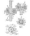
- Figure 1 illustrates a preferred embodiment of the present invention in combination with a rotatably driven spindle 10, a twist drill bit 12 (illustrative of various tools with which the invention can be used), and a typical three-jaw chuck 14 mounting the bit 12.
- the chuck 14 is one of a type known in the art and presently commercially available.
- the drive spindle 10 is made to rotate about an axis (not shown in the figures).
- the present invention functions to either reduce or increase the eccentricity of a central longitudinal axis 16 of the tool 12 with respect to the axis about which the spindle 10 is driven. If it is desired that the axis 16 of the tool 12 be aligned with the axis of rotation of the spindle 10, adjustments are made by use of the present invention in a manner as will be seen hereinafter in order to reduce the eccentricity to zero.
- Figure 1 illustrates an axis offset measuring device 18 having a dial indicator 20 by which eccentricity can be measured. It will be understood, however, that any appropriate means for measuring eccenrtricity can be employed.
- the present invention includes a male member 22 and a female member 24.
- the male member 22, as illustrated in the figures, is matable to the drive spindle 10.
- the female member 24 could, equally as well, be designed to be mated to the drive spindle 10.
- Mating of the male member 22 to the spindle 10 can be accomplished in a number of ways.
- Figure 2 illustrates a shank 26 which can be fitted into an aperture 28 in the spindle 10 and be secured there by ippropriate means. Securing can be effectuated by providing a locking taper fit between the shank 26 and an inner surface of the aperture 28 in the spindle 10, by collet chuck, or by other appropriate means.
- Figure 6 illustrates an alternative securing means. Because of the high frictional torque characteristics of "self-holding" tapers used, it may not be necessary to provide splines and keyways in order to insure that rotational motion of the spindle 10 is translated to the male member 22, but splining can be provided, if desired.
- the male member 22 further includes a hub portion extending downwardly from the shank 26.
- the hub 30 has an outer surface 32 which demarks the diameter of the hub 30.
- the male member 22 is provided with a flange-like portion 34 intermediate the shank 26 and the hub 30. While the hub 30 is shown as having a diameter larger than that of the shank 26, the flange-like portion 34 extends radially even beyond the outer surface 32 of the hub 30 in order to define a shoulder 36.
- Figure 1 illustrates the female member 24 as having a tapered shank 38 extending in an axial direction and receivable within a correspondingly tapered aperture 40 in the typical three-jaw chuck 14.
- any appropriate means for securing the female member shank 38 and the chuck 14 together in order to effect translation of rotational motion can be utilized.
- the female member 24 has, extending upwardly from the shank portion 38 as seen in Figure 2, an annular wall 42 with an inner surface 44 circumscribing a cavity 46 within the wall 42.
- the diameter of the cavity 46 is larger than that of the hub portion 30 of the male member so that the hub 30 can be received within the cavity 46.
- the invention provides for diametral clearance spacing between the outer surface 32 of the hub 30 and the inner surface 44 of the female member wall 42 so that the male member 22 and female member 24 can be adjusted laterally relative to one another.
- the longitudinal axis 16 of the tool 12 can be moved relative to the axis about which the drive spindle 10 rotates in order to adjust eccentricity.
- Figure 7 illustrates how this lateral adjustment of the male member 22 relative to the female member 24 can be effectuated. That figure shows four dog point set screws 50 passing radially through the annular wall 42 so that inner ends 54 enter into the cavity 46 to impinge upon the hub portion 30 of the male member 22. With the set screws 50 in their positions as indicated in Figure 7, hub 30 is generally concentric with the annular wall 42, and their centers generally coincide at index 56. If the set screw 50 approaching center from the upper left quadrant, as viewed in Figure 7, is withdrawn and the set screw approaching center from the lower right quadrant, as viewed in Figure 7, is moved radially inwardly, hub 30 will become offset so that its center is displaced to index 58.
- hub 30 will be displaced to index 60.
- Various combinations of adjustments can be made to position the hub 30 relative to the annular wall 42 so that a desired eccentricity is achieved.
- the invention employs the set screws 50 for adjusting the male and female members 22, 24 relative to one another and concurrently urging an axial end 48 of the female member wall 42, distal with respect to the three-jaw chuck 14, toward the flange portion 34 carried by the male member 22 and into tight engagement therewith.
- the shoulder 36 formed by the flange portion 34 of the male member 22 defines a plane which is substantially normal to a central axis of the male member 22, and the distal end 48 of the female member wall 42, similarly, defines a plane generally normal to the axis of the female member 24. Consequently, by bringing the axial end 48 of the female member 24 into tight engagement with the male member shoulder 36, the axes of the male and female members 22, 24 are made to be substantially parallel. By so doing, the axis 16 of the tool 12 will be made to be substantially parallel to the axis about which the spindle 10 is driven. Consequently, canting of the tool 12 will be precluded.
- the male member hub outer surface 32 is provided with a plurality of faceted surfaces 62 corresponding in number and location to the dog point set screws 50 carried by the female member 24.
- the faceted surfaces 62 on the hub outer surface 32 can be brought into registration with the locations of the set screws 50.
- the faceted surfaces 62 would be planar and, in the preferred embodiment, would be at an angle of approximately 5 degrees to an axis of the male member 22 with respect to which the outer surface 32 of the hub portion 30 is circularly cylindrical. The surfaces 62 would angle toward the axis as they approach the flange portion of the member 22.
- the axial locations of the apertures 52 through which the dog point set screws 50 reciprocate and the faceted surfaces 62 are such that the distal axial end 48 of the female member wall 42 will, in fact, engage the shoulder 36 defined by the flange portion 34 and be able to be urged tightly into engagement with the shoulder 36.
- movement of the set screws 50 can be along a perfectly radially extending path, since the engagement of the faceted surfaces 62 by the ends 54 of the set screws 50 will effect the axial movement of the female number 24 relative to the the male member 22 irrespective of the angle of attack of the set screws 50 against the faceted surfaces 62. It is deemed to be optimum, however, if the set screws 50 are reciprocable along paths normal to their respective corresponding faceted surfaces 62. The set screws 50, as seen in the figures, therefore, reciprocate along paths at an angle of 85 degrees relative to the axis with respect to which the inner surface 44 of the female member wall 42 is circularly cylindrical.
- each set screw 50 can be provided with a generally planar surface for engaging its corresponding faceted surface 62.
- a planar surface can be substantially perpendicular to the axis along which the set screw 50 reciprocates. With the axis of reciprocation generally perpendicular to the planar faceted surface 62, the planar surface of the corresponding set screw 50 will be parallel thereto.
- nylon pads can be applied to the threads of the set screws 50 in order to be able to adjust the screws 50 and rely upon their being maintained in the desired position.
- indicia can be provided on the outer surface of the female member wall 42 in order to be able to determine the radial positioning of the screws 50 and, consequently, the eccentricity being provided.
- the faceted surfaces 62 formed in the outer surface 32 of the hub portion 30 of the male member 22 are recessed to receive the dog point set screws 50.
- a machine operator need not rely upon merely the "wrench” effect created by engagement of the planar sufaces at the ends 54 of the set screws 50 with the faceted surfaces 62 to insure safe translation of rotational motion from the male member 22 to the female member 24.
- side walls 66 of the recesses can engage side walls of the set screws 50 to achieve a splining effect. As a result, even if set screws 50 should become withdrawn somewhat, translation of rotational motion to the female member 24 will still be insured.
- Means are provided to prevent the entry of metal chips between the axial end 48 of the female member wall 42 and the shoulder 36 defined by the flange portion 34 of the male member 22 in order to preclude scoring of the various internal surfaces. This is accomplished by placement and receipt of a resilient O-ring seal 64, resistent to oil and machining coolant, within an annular channel 65 formed in the distal axial end 48 of the female member wall 42.
- the male and female members 22, 24 would be free to diverge from one another and separate.
- these members are, of course, manufactured separately,, it is desirable that, once they are used in combination, they would be maintained together in a unitary assembly. By being so maintained, the chances are less likely of misplacing one of the members, and the seal between the distal axial end of the female member wall 42 and the shoulder 36 of the male member flange 34 can be maintained in place.
- FIGs 4, 5, and 6 illustrate the use of a snap ring 86 for maintaining the male and female members 22, 24 in an assembly.
- registered annual grooves 88, 90 can be formed in the outer surface 32 of the hub 30 and the inner surface 44 of the female member wall 42, respectively.
- An appropriately sized and shaped snap ring 86 can be positioned in the groove 90 in the wall 42 of the female member 24, and the hub 30 can then be urged into the cavity 46 in the female member 24. Because of resiliency afforded to the snap ring 86 and the discontinuity 92 therein at a location about its perimeter, the ring can be deformed outwardly in groove 90 as the hub 30 enters cavity 46.
- groove 88 achieves the axial location of the ring 86 received in groove 90 in the female member wall 42, it will snap inwardly into groove 88.
- hub 30 can be radiused as at 93. The male and female members 22, 24 will then be held together in assembly.
- the entrance to the cavity 46 can be provided with annular beveling 94. By so structuring the entrance to the cavity 46, “camming" action will occur to urge the ring 86 inwardly.
- a generally hexagonally shaped snap ring 86 is contemplated as being used in this embodiment. It will be understood, however, that snap rings configured in other fashions will also serve to accomplish the intended function
- the groove 90 formed in the female member wall 42 has an axial dimension greater then does the groove 88 formed in the hub 30.
- the snap ring 86 may be dimensioned closely to the axial dimension of the groove 88, the larger axial dimension of the groove 90 will afford some measure of relative axial movement between the male and female members 22, 24. As a result, the urging of the axial end 48 of the female member 24 into tight engagement with the shoulder 36 defined by the flange portion 34 of the male member 22 will not be precluded.
- Figures 2 and 3 illustrate an alternative embodiment of the mating means.
- the inner surface 44 of the female member wall 42 can be provided, at an axial end of the cavity 46 opposite the end from which the male member hub 30 enters the cavity 46, with an annular groove 68. This grove 68 would be proximate a base portion 70 of the female member 24.
- a bottom surface 72 of the male member hub 30 can carry a deformable lip 74 annular in structure.
- the lip 74 extends downwardly and outwardly from the location on the hub 30 from which it exits. Prior to the hub 30 being inserted into the cavity 46, the extremity 76 of the lip 74 would be within an imaginary cylinder extending from the hub 30 so that the lip 74 would not preclude insertion of the hub 30 into the cavity 46.
- the downward and inwardly facing surface of the lip 74 is illustrated as being convex as at 78 and would, optimally, be provided with a substantially constant radius of curvature. As the hub portion 30 of the male member 22 is inserted into the cavity 46, this convex surface 78 would be first to engage the base portion 70 of the female member 24 and would function as a "rolling fulcrum" on which the lip 74 would turn in deforming outwardly into the annular groove formed in the inner surface 44 of the female member wall 42.
- Figure 3 illustrates a manner in which the male member 22 could be married to the female member 24.
- An under surface 80 of the base portion 70 of the female member 24 could be seated on a jig 82 specially provided to receive the female member 24.
- the male member 22 could be made to approach the female member 24 and the hub 30 enter the cavity 46 formed within the wall 42 of the female member 24.
- the convex surface 78 of the lip 74 could function as the "rolling fulcrum" previously described, and the lip 74 would deform radially outwardly into the groove 68. With the lip 74 so deformed, the male and female portions 22, 24 would be retained together as a unitary assembly.
- the axial dimension of the groove 68 would be greater than the axial dimension of the lip 74 as measured once the lip 74 is deformed and received within the groove 68.
- Figure 1 illustrates a collar threaded onto this structure.
- a collar can be used to facilitate removal of the chuck from the female member 24 when, for example, the user of the implement desires to change the tool 12.
- the collar 98 By rotating the collar 98 so that the threads 96 urge it downwardly, the collar 98 is brought to bear upon the upper end of the chuck 14, and as the collar 98 is continued to be rotated to move it downwardly, mechanical advantage will he o tained to push the chuck 14 out of engagement with the female member 24.
- the present invention can be made from one of various materials suited to applications of the particular type of device. It may be constructed of many carbon or alloy steels, depending upon the strength and resistence to damage required in actual practice. It has been found that SAE 1117 leaded, free machining steel, surface hardened by carbonizing or nitriding by treatment by the Kolene Corporation Melanite® QPQ process is a preferred material.
Landscapes
- Engineering & Computer Science (AREA)
- Mechanical Engineering (AREA)
- Gripping On Spindles (AREA)
Applications Claiming Priority (2)
| Application Number | Priority Date | Filing Date | Title |
|---|---|---|---|
| US06/677,870 US4666353A (en) | 1984-12-03 | 1984-12-03 | Eccentricity adjustment device |
| US677870 | 1984-12-03 |
Publications (1)
| Publication Number | Publication Date |
|---|---|
| EP0187469A1 true EP0187469A1 (de) | 1986-07-16 |
Family
ID=24720424
Family Applications (1)
| Application Number | Title | Priority Date | Filing Date |
|---|---|---|---|
| EP85308702A Withdrawn EP0187469A1 (de) | 1984-12-03 | 1985-11-29 | Vorrichtung zum Einstellen der Exzentrizität |
Country Status (3)
| Country | Link |
|---|---|
| US (1) | US4666353A (de) |
| EP (1) | EP0187469A1 (de) |
| CA (1) | CA1254404A (de) |
Cited By (1)
| Publication number | Priority date | Publication date | Assignee | Title |
|---|---|---|---|---|
| EP0508152A3 (en) * | 1991-03-13 | 1993-03-03 | Mitsubishi Materials Corporation | Cutting tool |
Families Citing this family (10)
| Publication number | Priority date | Publication date | Assignee | Title |
|---|---|---|---|---|
| US4845997A (en) * | 1988-02-17 | 1989-07-11 | Trustees Of The University Of Pennsylvania | Self-alignment grip for mechanical testing |
| JP3811570B2 (ja) * | 1998-04-14 | 2006-08-23 | 富士精工株式会社 | 内径仕上加工方法およびリーマ |
| DE10259257A1 (de) * | 2002-12-11 | 2004-06-24 | Marquart, Ingeborg | Vorrichtung und Verfahren zum zentrierten Spannen von rotierend antreibbaren Teilen |
| DE102004042520B3 (de) * | 2004-09-02 | 2006-04-06 | Wto Werkzeug-Einrichtungen Gmbh | Werkzeugträger für Werkzeuge bei Werkzeugmaschinen |
| US20060115337A1 (en) * | 2004-12-01 | 2006-06-01 | Fusao Higashi | Runout eliminating collet chuck |
| US20100171275A1 (en) * | 2009-01-02 | 2010-07-08 | Bill Nguyen | Collet with multiple keys way |
| JP2018503778A (ja) * | 2014-11-12 | 2018-02-08 | クマール マダ,ビジャイ | 放射方向および軸方向補正を伴う新規な精密モジュール保持システム |
| US10265777B2 (en) * | 2017-07-31 | 2019-04-23 | Bourn & Koch, Inc. | Spacer for arbor of machining system, machining system incorporating same, and associated method |
| US10866256B2 (en) * | 2018-07-20 | 2020-12-15 | George V. Zusman | Universal sensor mount |
| US11577327B2 (en) * | 2021-03-24 | 2023-02-14 | Huston G. Cockrill | Systems, devices, and/or methods for drilling |
Citations (7)
| Publication number | Priority date | Publication date | Assignee | Title |
|---|---|---|---|---|
| DE399267C (de) * | 1923-09-22 | 1924-07-31 | Wilhelm Uecker | Loesevorrichtung fuer Werkzeuge mit konischem Schaft |
| US2733073A (en) * | 1956-01-31 | phillips | ||
| DE955559C (de) * | 1954-06-05 | 1957-01-03 | Duss Maschf | Vorrichtung zum Abziehen eines Bohrfutters |
| US2785902A (en) * | 1954-10-04 | 1957-03-19 | Casimir M Zajdel | Tool holders for screw machines |
| US2828132A (en) * | 1954-12-22 | 1958-03-25 | Kendall Parmelee G | Concentricity control apparatus |
| US2984494A (en) * | 1959-12-18 | 1961-05-16 | Frank A Alston | Adjustable mounts for self-centering chucks |
| US3088746A (en) * | 1960-12-08 | 1963-05-07 | Whiton Machine Company | Radially adjustable chuck |
Family Cites Families (11)
| Publication number | Priority date | Publication date | Assignee | Title |
|---|---|---|---|---|
| US2460673A (en) * | 1944-06-09 | 1949-02-01 | Irvine J Berscheid | Detachable bit |
| US2524485A (en) * | 1949-04-09 | 1950-10-03 | Cushman Chuck Co | Compensating-jaw chuck |
| US2833544A (en) * | 1956-04-09 | 1958-05-06 | Prec Proc Co | Compensating tool holder |
| US2852265A (en) * | 1956-04-10 | 1958-09-16 | Gen Motors Corp | Work holder and centering means |
| DE1402986A1 (de) * | 1961-03-10 | 1969-10-02 | Kostyrka Dipl Ing Alfred | Spannfutter |
| US3501983A (en) * | 1966-02-23 | 1970-03-24 | Us Army | Method and apparatus for module alignment of ocular systems |
| US3484115A (en) * | 1967-04-27 | 1969-12-16 | Richard C Meyer | Adjustable tool chuck |
| US3603535A (en) * | 1968-11-13 | 1971-09-07 | Maurice Depolo | Lifesaving support system |
| US3633923A (en) * | 1969-12-08 | 1972-01-11 | Katsumi Watanabe | Handy acoustic reproducing device |
| US3761103A (en) * | 1971-12-01 | 1973-09-25 | C Zajdel | Tool holders |
| US4281482A (en) * | 1979-10-04 | 1981-08-04 | Sunnen Products Company | Spindle nose for machine tools |
-
1984
- 1984-12-03 US US06/677,870 patent/US4666353A/en not_active Expired - Fee Related
-
1985
- 1985-11-29 EP EP85308702A patent/EP0187469A1/de not_active Withdrawn
- 1985-12-02 CA CA000496633A patent/CA1254404A/en not_active Expired
Patent Citations (7)
| Publication number | Priority date | Publication date | Assignee | Title |
|---|---|---|---|---|
| US2733073A (en) * | 1956-01-31 | phillips | ||
| DE399267C (de) * | 1923-09-22 | 1924-07-31 | Wilhelm Uecker | Loesevorrichtung fuer Werkzeuge mit konischem Schaft |
| DE955559C (de) * | 1954-06-05 | 1957-01-03 | Duss Maschf | Vorrichtung zum Abziehen eines Bohrfutters |
| US2785902A (en) * | 1954-10-04 | 1957-03-19 | Casimir M Zajdel | Tool holders for screw machines |
| US2828132A (en) * | 1954-12-22 | 1958-03-25 | Kendall Parmelee G | Concentricity control apparatus |
| US2984494A (en) * | 1959-12-18 | 1961-05-16 | Frank A Alston | Adjustable mounts for self-centering chucks |
| US3088746A (en) * | 1960-12-08 | 1963-05-07 | Whiton Machine Company | Radially adjustable chuck |
Cited By (4)
| Publication number | Priority date | Publication date | Assignee | Title |
|---|---|---|---|---|
| EP0508152A3 (en) * | 1991-03-13 | 1993-03-03 | Mitsubishi Materials Corporation | Cutting tool |
| US5314273A (en) * | 1991-03-13 | 1994-05-24 | Mitsubishi Materials Corporation | Cutting tool |
| US5391022A (en) * | 1991-03-13 | 1995-02-21 | Mitsubishi Materials Corporation | Cutting tool |
| EP0663252A3 (de) * | 1991-03-13 | 1995-12-20 | Mitsubishi Materials Corp | Schneidwerkzeug. |
Also Published As
| Publication number | Publication date |
|---|---|
| US4666353A (en) | 1987-05-19 |
| CA1254404A (en) | 1989-05-23 |
Similar Documents
| Publication | Publication Date | Title |
|---|---|---|
| AU724736B2 (en) | Tool-less machine tool chuck | |
| US4666353A (en) | Eccentricity adjustment device | |
| US7168900B2 (en) | Total support with a collet chuck receiver | |
| WO1997048513A9 (en) | Tool-less machine tool chuck | |
| DE102017104914B4 (de) | Anschlag für ein Bohr-, Fräs- oder Senkwerkzeug | |
| US4611960A (en) | Tool holder | |
| US5601295A (en) | Tool holder system for industrial cutting tools | |
| US5096212A (en) | Chuck for power tools | |
| EP0446198B1 (de) | Schnellwechselmechanismus mit exzentrischer sperrvorrichtung | |
| US20040009047A1 (en) | Tool clamping device | |
| US4928981A (en) | Jaw locking means for chucks | |
| US4634324A (en) | Tool holder with radial adjustment means for a tool, in particular a rotary tool | |
| CA1287484C (en) | Clamping means for machine tool holders | |
| US3767217A (en) | Variable chuck | |
| US7172377B2 (en) | Router or cutter bit chuck or extension | |
| US5716056A (en) | Internally squeezing sealable collet | |
| EP0501636B1 (de) | Werkzeughaltmontage | |
| US3724965A (en) | Double bladed cutting tool | |
| CA2181102A1 (en) | Universal tool holding device for use with a power-driven, rotatable spindle machine | |
| JPS63127846A (ja) | 偏心調節装置 | |
| EP0245354B1 (de) | Befestigungsmittel für werkstück | |
| JPH0655320A (ja) | 複合ツール | |
| EP1445050A1 (de) | Werkzeugadapter | |
| RU1771891C (ru) | Режущий инструмент | |
| US20020137449A1 (en) | Tool for sizing an O.D. surface of a cylindrical workpiece |
Legal Events
| Date | Code | Title | Description |
|---|---|---|---|
| PUAI | Public reference made under article 153(3) epc to a published international application that has entered the european phase |
Free format text: ORIGINAL CODE: 0009012 |
|
| AK | Designated contracting states |
Kind code of ref document: A1 Designated state(s): BE DE FR GB IT NL SE |
|
| 17P | Request for examination filed |
Effective date: 19870116 |
|
| 17Q | First examination report despatched |
Effective date: 19871005 |
|
| STAA | Information on the status of an ep patent application or granted ep patent |
Free format text: STATUS: THE APPLICATION IS DEEMED TO BE WITHDRAWN |
|
| 18D | Application deemed to be withdrawn |
Effective date: 19880226 |
|
| RIN1 | Information on inventor provided before grant (corrected) |
Inventor name: MICEK, JOHN |