EP0187552B1 - Seilschwebebahn - Google Patents
Seilschwebebahn Download PDFInfo
- Publication number
- EP0187552B1 EP0187552B1 EP85400770A EP85400770A EP0187552B1 EP 0187552 B1 EP0187552 B1 EP 0187552B1 EP 85400770 A EP85400770 A EP 85400770A EP 85400770 A EP85400770 A EP 85400770A EP 0187552 B1 EP0187552 B1 EP 0187552B1
- Authority
- EP
- European Patent Office
- Prior art keywords
- rollers
- cables
- support
- carriage
- pylon
- Prior art date
- Legal status (The legal status is an assumption and is not a legal conclusion. Google has not performed a legal analysis and makes no representation as to the accuracy of the status listed.)
- Expired - Lifetime
Links
- 238000011144 upstream manufacturing Methods 0.000 claims description 19
- 229920001971 elastomer Polymers 0.000 claims description 6
- 230000001360 synchronised effect Effects 0.000 claims description 4
- 239000000806 elastomer Substances 0.000 claims description 3
- 125000006850 spacer group Chemical group 0.000 claims description 2
- 210000000080 chela (arthropods) Anatomy 0.000 claims 21
- 230000003014 reinforcing effect Effects 0.000 claims 4
- 238000009434 installation Methods 0.000 description 28
- 239000000543 intermediate Substances 0.000 description 19
- 230000006835 compression Effects 0.000 description 14
- 238000007906 compression Methods 0.000 description 14
- 239000000725 suspension Substances 0.000 description 7
- 230000001174 ascending effect Effects 0.000 description 3
- 239000000969 carrier Substances 0.000 description 3
- 230000000694 effects Effects 0.000 description 3
- 238000012423 maintenance Methods 0.000 description 3
- 239000000463 material Substances 0.000 description 2
- 238000011084 recovery Methods 0.000 description 2
- 206010044565 Tremor Diseases 0.000 description 1
- 230000001133 acceleration Effects 0.000 description 1
- 238000010276 construction Methods 0.000 description 1
- 238000006073 displacement reaction Methods 0.000 description 1
- 230000010354 integration Effects 0.000 description 1
- 238000002955 isolation Methods 0.000 description 1
- 239000002184 metal Substances 0.000 description 1
- 238000005096 rolling process Methods 0.000 description 1
Images





Classifications
-
- B—PERFORMING OPERATIONS; TRANSPORTING
- B61—RAILWAYS
- B61B—RAILWAY SYSTEMS; EQUIPMENT THEREFOR NOT OTHERWISE PROVIDED FOR
- B61B12/00—Component parts, details or accessories not provided for in groups B61B7/00 - B61B11/00
- B61B12/02—Suspension of the load; Guiding means, e.g. wheels; Attaching traction cables
-
- B—PERFORMING OPERATIONS; TRANSPORTING
- B61—RAILWAYS
- B61B—RAILWAY SYSTEMS; EQUIPMENT THEREFOR NOT OTHERWISE PROVIDED FOR
- B61B12/00—Component parts, details or accessories not provided for in groups B61B7/00 - B61B11/00
- B61B12/12—Cable grippers; Haulage clips
- B61B12/122—Cable grippers; Haulage clips for aerial ropeways
-
- B—PERFORMING OPERATIONS; TRANSPORTING
- B61—RAILWAYS
- B61B—RAILWAY SYSTEMS; EQUIPMENT THEREFOR NOT OTHERWISE PROVIDED FOR
- B61B7/00—Rope railway systems with suspended flexible tracks
- B61B7/04—Rope railway systems with suspended flexible tracks with suspended tracks serving as haulage cables
- B61B7/045—Rope railway systems with suspended flexible tracks with suspended tracks serving as haulage cables having in each direction more than one track serving as haulage cables
Definitions
- the invention relates to an overhead cable transport installation of the type comprising one or more vehicles which are spaced apart and associated rigidly but disengageably by clamps carried by a carriage associated with a suspension, with two endless cables, carriers and tractors, parallel to each other, placed one beside the other in the horizontal direction, driven by continuous scrolling at the same speed and supported by pylons supported by intermediate pylons.
- a clamp comprising a clamp body rigidly associated with the chassis of the carriage, a fixed jaw carried by the clamp body, a movable jaw carried by an arm articulated to the clamp body; elastic means for returning the movable jaw towards the fixed jaw such as a spring arranged substantially vertically; and a clutch release roller mounted to pivot freely on the arm about a substantially horizontal and transverse axis, capable of cooperating with a clutch ramp forming part of the declutching and clutch means located in each station. end.
- Transport installations with overhead cables are also known in which each tractor carrying cable passes at the level of a pylon on a pendulum which may include support rollers or compression rollers.
- the pylons are then respectively called support pylons or compression pylons.
- These pylons include a base, a vertical barrel or extending upwards, a horizontal and transverse bracket relative to the cable tray and two series of rollers for supporting or compressing the cables.
- connection between the two cables defines a rigid quadrilateral formed by the clamps of the vehicles, which performs a synchronous drive while avoiding any integration of offset and obliquing of the vehicles.
- the realization of transport installations with two overhead cables with cabins that can be of large capacity requires that the pylons are designed to allow the passage of the cabin carrier trolley, the maintenance of the cables in a constant relative position and finally to marry the generally curved shape of the cable tray in front of a pylon.
- European patent application 0 093 680 provides for a trapezoidal arrangement of the clamps.
- the clamps form an equal height above the cable in any plane perpendicular to the line. It turns out in practice that such provisions do not allow a passage of the carriage to the right of the pylons in conditions of sufficient safety and comfort.
- the invention therefore aims to remedy these drawbacks, and for this purpose, it provides an overhead cable transport installation comprising one or more vehicles spaced apart and associated rigidly but disengageably by two pairs of clamps carried by an associated carriage to a suspension, to two endless cables, carriers and tractors, parallel to each other, placed one beside the other in the horizontal direction, driven by continuous scrolling at the same speed and guided by pylons support and / or compression intermediates each comprising two series of support and / or compression rollers for the two cables, each of the pairs of clamps being associated with one of the two cables, the two pairs of clamps defining a rigid quadrilateral, which, in the engaged state, favors the synchronous scrolling of the two cables, characterized in that each clamp comprises a clamp body mounted to pivot relative to the ch chassis of the carriage around a horizontal and transverse axis by means of bearings fixed to the side members of the chassis, and in that each clamp body comprises a hoop part which projects outward in a horizontal and transverse direction to constitute the fixed jaw,
- the invention relates to an overhead cable transport installation of the type comprising one or generally several vehicles 1 spaced apart (individually or in groups) along two cables 2a, 2b to which they are rigidly associated, but disengageably by clamps tightening 3.
- the collets 3 are carried by a carriage 4 - described in more detail below - to which is articulated around a horizontal and transverse axis 5 the upper end part 6 of a vertical suspension 7, rigidly integral, to its part lower end 8 of the vehicle chassis 1.
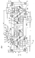
- the two cables 2a, 2b, - which do not in themselves constitute the invention - are endless, separate from each other, carriers and tractors, parallel to each other, placed one beside the other on the other in the horizontal direction, driven to continuous scrolling at the same speed. They extend between two end stations such as the end station 9 shown in FIG. 2, for loading and unloading vehicles 1, and they are supported in an intermediate manner by one or more pylons 10 which will be described in more detail below.
- the vehicle 1 shown in Figure 1 is a cabin for the transportation of passengers.
- the vehicle 1 can also be a bucket or the like for transporting materials.
- the vehicle 1 comprises, in addition to its chassis, a body, movable doors, windows or portholes and all the usual equipment (bumpers, exit hatches, etc.).
- Each end station 9 which does not in itself constitute the invention comprises two wheels 11a, 11b, driving drives of the two cables 2a, 2b (in the case of FIG. 2, the axes of the two wheels 11a, 11 are vertical however these axes can be inclined in any way); fixed vehicle support means 1, such as a rail placed substantially horizontally and having a general shape of U bypassing the drive wheels, not shown; upstream means for disengaging the clamps making it possible to dissociate a vehicle 1 from the cables 2a, 2b in order to store it on fixed support means, not shown; downstream means for clutching the clamps making it possible to associate a vehicle 1 stored on the fixed support means for the cables 2a, 2b, not shown; motor means for driving the driving wheels 11 a, 11 b, at the same speed, not shown; means for tensioning the cables 2a, 2b, not shown; means of access to vehicles 1, such as platforms, allowing, for example in the case of a cabin, travelers to enter and leave them when they are on the stationary support means stationary or at low speed
- Upstream and downstream refer to the direction of movement of the vehicles 1, along the cables 2a, 2b.
- An intermediate pylon 10 is intended to support the two cables 2a, 2b, associated with the vehicles 1 (ascending or descending) and preferably the two pairs of cables of the ascending and descending vehicles 2a, 2b, 12a, 12b, these two cables being able to result from two cables 2a, 12a, on the one hand, and 2b, 12b, on the other hand, endless, and offset transversely.
- the pylon 10 can be designed to support only two cables 2a, 2b, from an ascending or descending cabin.
- Such a pylon 10 comprises in a manner known per se, a base 13 anchored to the ground; a barrel 14 vertical or directed upwards, rigidly associated with the base 13; a bracket 15 rigidly fixed to the upper end of the barrel 14 having a general horizontal transverse direction relative to the cables 2a, 2b, 12a, 12b; two stirrups 16a, 16b having the general shape of an inverted U, arranged vertically, transversely and coplanarly with the two opposite extreme free parts of the bracket 15; two pairs of pendulums extending in the horizontal or substantially horizontal direction, the two pendulums of each pair being spaced transversely and facing each other and associated with the vertical branches descending from a stirrup 16a, 16b; and finally rollers 17 carried by the pendulums in the grooves through which the cables 2a, 2b, 12a, 12b pass.
- rollers 17 - and therefore the pylons 10 which support them - are of two possible types: support or compression, depending on whether they support the cables 2a, 2b, 12a, 12b, from below ( Figures 2, 6, 7) or at on the contrary that they press on these cables 2a, 2b, 12a, 12b, from above (FIGS. 8, 9), this so that the cables 2a, 2b, 12a, 12b follow the desirable path taking into account the accidents on the ground while being maintained and guided.
- cables 2a, 2b, 12a, 12b are inclined, one of the end stations being located at a lower level (downstream station for cables 2a, 2b) and the other station being located at a higher level (upstream station for cables 2a, 2b). Consequently, in the text, the words “horizontal”, “vertical” are relative and refer either to the usual physical concept, or in a relative way on the one hand to the trace of the plane of the cables 2a, 2b, 12a, 12b, relative to a vertical plane orthogonal to the latter and parallel to the cables, on the other hand to a straight line perpendicular to the plane of the cables.
- the “axial” and “transverse” directions are understood to be respectively parallel to the axes of the cables 2a, 2b, 12a, 12b and perpendicular horizontally to the cables 2a, 2b, 12a, 12b. It is understood that, with some exceptions, the horizontal, vertical, axial or transverse directions also generally include those which are adjacent to them.
- the assembly comprising two cables 2a, 2b or 12a, 12b, of the same vehicle 1, this vehicle 1, its suspension 7, its carriage 4, the corresponding bracket 16a or 16b, of an intermediate pylon 10 and its two pendulums have an axial vertical plane of symmetry P equidistant from two cables considered 2a, 2b or 12a, 12b.
- an intermediate pylon 10 if it supports two pairs of cables, has an axial vertical plane of symmetry U passing through the base 13 and the barrel 14.
- a clamp 3 comprises a clamp body 18 associated with the chassis 19 of the carriage 4; a fixed jaw 20 carried by the clamp body 18, in particular in two parts 20a, 20b separated axially; a movable jaw 21 placed between the two parts 20a, 20b, of the fixed jaw, carried by the outer free end 22 and lower part of an arm 23 forming a lever situated in a transverse plane, having a general shape of L, articulated to the body clamp 18 around an axial axis 24; elastic return means 25 from the movable jaw 21 towards the fixed jaw 20 (corresponding to the engaged state) such as a spring disposed substantially vertically and a disengaging roller 26 of the clamp 3, mounted with free pivoting at the end free 27 inside and upper of the arm 23 around a substantially horizontal and transverse axis 28 and capable of cooperating with the upstream declutching and downstream clutch means taking the form of an inclined ramp 29.
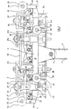
- the carriage 4 comprises a pair of clamps 3'a, 3 "a associated with the cable 2a and a pair of clamps 3'b, 3" b, associated with the cable 2b.
- the chassis 19 of the carriage 4 being rigid and the clamps 3 being associated therewith also rigidly seen from above, that is to say in plan and subject to what is said below with reference to the elastic means of association of the clamp body 18 with the chassis 19, the two pairs of clamps 3'a, 3 "a, 3'b, 3" b define a "rigid" quadrilateral in the form of a parallelogram which, in the engaged state, promotes displacement synchronous of the two cables 2a, 2b.
- the clamps of the two pairs of clamps are also spaced from one another in the axial direction, for example by a distance D of the order of 800mm.
- This arrangement increases the compactness of the carriage 4, therefore also its weight and limits the spacing between the two cables 2a, 2b which can be of the order of 750 mm.
- the quadrilateral has the shape of a rectangle.
- the two end clamps 3'a, 3'b on the one hand, 3 "a, 3" b on the other hand are immediately adjacent to each other in the axial direction, which gives the carriage 4 the minimum space possible in the axial direction. Consequently, two end clamps are spaced from one another in the axial direction by a distance corresponding substantially to the axial size of a clamp 3, for example of the order of 300 mm.
- the two central clamps which belong to the two distinct pairs of clamps, namely 3'a and 3'b are separated axially from each other by a distance at least equal to the axial size of the suspension 7.
- the spacing between the two transverse axes of the two central clamps 3'a, 3 "b is of the order of 500 mm.
- the two pairs of pliers 3'a, 3 "a on the one hand, 3'b, 3" b on the other hand are separated transversely from the minimum distance possi ble taking into account the size of the clamps.
- the clamps 3 project transversely outward from the entire carriage 4 located between the two cables 2a, 2b.
- the carriage 4 mainly comprises two axial beams 30a, 30b, and crosspieces, in particular of ends 31. These beams 30a, 30b, can be separated from one another, transversely, by about 450 mm. As for the two end crossmembers which define the maximum size of the carriage 4, they can be spaced from each other by a distance of the order of about 1600 mm.
- the arrangement which has just been described is such that the clamps 3'a, 3 "a, 3'b, 3" b, extend practically between the two longitudinal members 30a, 30b, in addition to their projecting part constituted by the fixed jaws 20 and mobile 21.
- the elastic means 25 as well as the release rollers 26 are located in the immediate vicinity. from the axial vertical plane of symmetry P.
- the raceways of the clutch release rollers 26 of the two pairs of pliers 3'a, 3 "a, 3'b, 3" b are spaced from one another, in the engaged state, of the order of approximately 60 mm.
- the installation comprises a clutch-release ramp 29, unique at each end of each pair of cables 2a, 2b or 12a, 12b, that is to say a single ramp on each side of each end station 9 on which the disengaging rollers 26 of the two pairs of pliers 3'a, 3 "a, 3'b, 3" b come to bear.
- a clamp body 18 is associated with the chassis 19 of the carriage 4, in particular the side members 30a, 30b, by elastically deformable members 32 such as blocks of rubber or elastomer.
- These members 32 have the function of ensuring a general maintenance of the clamp 3 relative to the chassis 19 with however the possibility of a small limited clearance on either side of its normal rest position around its transverse axis of symmetry 33. This movement is for example of the order of 2 °.
- This arrangement allows the clamps to marry without excessive stress the curved shape of the cable tray 2a, 2b.
- the members 32 are only slightly deformable and under the effect of sufficient force so that the clamp body 18 is normally held without being able to pivot inopportune about the axis 33.
- a clamp body 18 preferably comprises a part 34 extending axially and in a vertical plane and having a general shape of a concavity arch turned downwards. This part 34 projects outward, horizontally and transversely to constitute the fixed jaw 20.
- These two lower free end portions 35 are associated with the chassis 19 in particular with the side members 30a, 30b, by the elastically deformable members 32.
- the two parts 20a, 20b, of a fixed jaw are extended axially by needles 36 which cooperate with the cables 2a, 2b, the internal needles of the two clamps each pair of pliers 3'a, 3 "a on the one hand, 3'b, 3" b, on the other hand, are distinct and are not rigidly associated with each other.
- the clamp body 18 is pivotally mounted about its transverse axis 33 in bearings 37a, 37b, fixed to the side members 30a, 30b, on their inner face ( Figure 5).
- the carriage 4 comprises support means 38, in particular support rollers 39, mounted with free pivoting around horizontal and transverse axes 40, and guide means 41, in particular guide rollers 42, mounted at free pivoting around vertical axes 43, making it possible respectively to support the carriage 4 and to guide it in transverse direction when the clamps 3 are disengaged, in the end stations 9.
- Each of the end crosspieces 31 has at each of its free ends a tab 44 located in an axial vertical plane at the end part of which is pivotally mounted around a horizontal and transverse axis 45 a comfort roller 46 intended for drive on a track 47 associated with an intermediate pylon 10.
- FIG. 3 are shown the comfort rollers 46 of a carriage 4 placed at the ends of the latter in an axial direction, intended to roll on a rolling track 47 associated with an intermediate pylon 10 of the compression type.
- the tab 44 is directed upwards.
- An intermediate pylon 10 has two raceways 47 for the comfort rollers 46, generally following the cable routing profile 2a, 2b as defined by the rollers 17, while being very slightly more curved than this profile
- Theoretical routing of cables so as to be spaced from it vertically upwards or downwards depending on whether it is a support roller pylon (left part in Figure 2) or compression ( Figures 8 and 9) except at its ends.
- the upward or downward spacing is understood not to mean the relative overall position of the tracks 47 relative to the rollers 17, but the relative variation in spacing between them.
- the track 47 can be placed as a whole above or below the rollers 17 depending on the configuration.
- the tracks 47 are placed next to the lower part of the rollers 17. It follows from this arrangement that by passing over a pylon, the carriage rolls thanks to its comfort rollers 46 on the tracks 47, respectively above or below the latter, depending on whether the pylon is of the support or compression type, while being driven by the cables 2a, 2b, which are very slightly spaced from the grooves of the rollers 17. This function is all the better fulfilled as the comfort rollers 46 are spaced in the axial direction by the greatest possible distance.
- the clamp body 18 in the engaged state of the clamp ( Figure 3), the clamp body 18 is supported on the upper part of the corresponding cable 2a, 2b.
- the fixed and mobile jaws 20, 21 are applied to the internal and external lateral parts of the cable.
- the lower part of the cable 2a, 2b remains substantially free.
- This arrangement simultaneously ensures good support of the carriage 4 on the cables 2a, 2b, while allowing smooth passage of the rollers 17, of the pylons, especially when they do not have a raceway 47.
- a carriage 4 also comprises two friction bands 48 extending axially, placed horizontally coplanar and spaced transversely from each other above the middle part of the side members 30a, 30b to which they are rigidly associated by vertical tabs 49
- These friction bands 48 are intended to be functionally operational in each end station 9, either to slow down the carriage 4 separated from the cables 2a, 2b, or, on the contrary, to drive this carriage before it is coupled to the cables 2a, 2b.
- the elastic means 25 such as a helical spring are mounted between an upper cup 50 and a lower cup 51.
- the upper cup 50 is associated with the free end 27 of the arm 23 around an axis of articulation 52 horizontal and axial .
- the lower cup 51 is fixed to the end part of a stirrup 53 disposed substantially vertically, associated with its upper end part to the clamp body 18 about an axis 54, horizontal and axial substantially situated in the vertical axial plane of symmetry P .
- a pylon of an installation according to the invention is described below with reference to the case of a pylon with support rollers, but it is clear that this description can be clearly adapted to the case of a pylon with compression rollers .
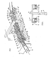
- the pylon 10 comprises two support pendulums 55a, 55b, symmetrical with respect to the plane P, articulated at their middle part with free pivoting around a horizontal and transverse axis 56 to a stirrup 16 placed vertically and transversely rigidly associated with the bracket 15.
- This stirrup having a general shape of an inverted U comprises a core (not shown) rigidly associated with the bracket 15 or, as a variant, does not include a core, the latter forming an integral part of the bracket 15 and constituting its extreme part free, and two wings 57a, 57b, symmetrical with respect to the plane P, directed vertically and downwards, to the lower free end part of which is the axis 56.
- the pendulums 55a, 55b are associated with free pivoting on the internal faces of the wings 57a, 57b, around the axis 56 by two pins 56a, 56b, leaving free space between the two support pendulums 55a, 55b.
- the two support pendulums 55a, 55b are rectilinear and constituted by a profiled metal part with a square or rectangular cross section.
- the pylon 10 comprises, on the other hand, several elementary pendulums 58 comprising the rollers 17, articulated with free pivoting, directly or indirectly on the support pendulums 55a, 55b, around horizontal and transverse axes 59.
- These elementary pendulums 58 are placed one after the other and close to each other over the necessary length, taking into account the support forces exerted by the cables 2a, 2b and the more or less curved path of the cable tray.
- a typical and preferred embodiment is that shown in FIG. 7 in which four elementary pendulums 58 are provided.
- An elementary balance wheel 58 comprises, on the one hand, two longitudinal members 60a, 60b for supporting the rollers respectively 17a, 17b, spaced transversely from one another and symmetrical with respect to the plane P and, on the other hand, an arch stiffening 61 rigidly connecting together the two beams 60a, 60b.
- Each spar 60a, 60b preferably comprises two parts spaced transversely from one another but rigidly integral with one another, namely, for the spar 60a the two parts 60'a and 60 "a and for the spar 60b parts 60'b and 60 “b. Between each pair of parts 60'a, 60 “a, 60'b, 60" b, the support rollers 17a, 17b are mounted for free pivoting.
- the two parts 60'a, 60 "a, 60'b, 60" b of a beam 60a, 60b are rigidly associated with one another by a central spacer 62.
- An elementary balance wheel 58 has two upstream rollers lTa, 17'b and two downstream rollers 17 “a, 17” b, the upstream rollers 17'a, 17'b, on the one hand, and the downstream rollers 17 “a, 17 “b on the other hand, having coaxial pivot axes respectively 63 '(upstream axis) and 63" (downstream axis).
- each of the axes 63', 63 " is in two parts in order to leave the central space free between the rollers to allow the carriage 4 and the suspension 7 to pass.
- the two axes 63 ', 63 are provided at the two free end portions 64', 64" of the side members 60a, 60b.
- the stiffening arch 61 preferably connects the two pieces of side members 60a, 60b, located towards the outside, ie 60'a and 60'b.
- This stiffening hoop is placed vertically and transversely and has a general shape of an inverted U comprising a central web 65 horizontal and transverse and two wings 66a, 66b, lateral verticals and directed downwards, rigidly associated with their lower free end part 67 to longitudinal members 60a, 60b in particular at the external parts 60'a, 60'b.
- the stiffening arch 61 has, in cross section, a T shape, this to guarantee its non-deformability.
- the core 65 is preferably connected to the wings 66a, 66b by cut sides 68a, 68b.
- An elementary balance wheel 58 preferably comprises a single stiffening arch 61 placed at one of the extreme free parts of the side members 60a, 60b and preferably on the side of the extreme free part 64 ′, for example upstream.
- an elementary balance wheel 58 In elevation (that is to say seen from the side), an elementary balance wheel 58 therefore has a general shape of L, the horizontal branch of which is formed by the side members 60a, 60b and the vertical branch of which consists of the arch of stiffening 61.
- a pylon as just described comprises means 69 for preventing the cables 2a, 2b from escaping from the grooves of the rollers 17 which support them.
- These means are for example placed on the internal faces of the wings 66a, 66b of a hoop 61 and above the groove of the corresponding rollers 17'a, 17 “b.
- These means are constituted for example by a plate 69 projecting towards the interior and curved around a vertical axis with convexity facing the plane P.
- the intermediate pylon 10 of an installation according to the invention preferably includes means 70 for recovering the cables 2a, 2b, if these escape the grooves of the corresponding support rollers 17'a, 17 “a, 17'b, 17 “b.
- These recovery means 70 are constituted for example by a section of gutter open upwards, rigidly fixed to the internal face of each internal part 60 "a, 60" b in the vicinity of the upstream rollers 17'a, 17'b.
- these gutters are curved around a horizontal and transverse axis with convexity facing upwards. Their size in the transverse direction is limited substantially to the width of a cable such as 2a, 2b so as not to prevent the passage of the suspension 7 and of the carriage 4.
- the upstream rollers 17'a, 17'b are associated, on the one hand, with the means 69 for preventing the cables 2a, 2b from escaping from the grooves of the rollers, and on the other hand, the recovery means 70 cables 2a, 2b.
- two successive elementary pendulums 58 are arranged in the same direction, that is to say with the stiffening hoops 61 disposed upstream.
- These two successive elementary pendulums 58 are mounted articulated with free pivoting around axes 71 ′, 71 "horizontal and transverse to the two free end portions 72 ′, 72 ′′ of two intermediate parts 73a, 73b, symmetrical with respect to the plane P, articulated freely pivoting about a horizontal axis 74 and transverse to the support beam 55a, 55b, directly or indirectly.
- the axis 74 is located in the middle part of the intermediate parts 73a, 73b.
- the pylon comprises four successive elementary pendulums 58 forming an upstream group 75 'of two elementary pendulums 58 and a downstream group 75 "of two other elementary pendulums 58. All of these pendulums are arranged in the same direction.
- the two elementary pendulums 58 of the upstream group 75 ' are pivotally mounted on two intermediate parts 73a, 73b, articulated to the support pendulums 55a, 55b around the axis 74 located at the upstream free end 76' of these pendulums support 55a, 55b.
- rollers of these two elementary rockers 58 of the upstream group 75 follow each other at regular intervals. They are further followed, with the same interval by rollers of the downstream group 75 "which has the same structure as described above, articulated at the downstream free end portion 76" of the pendulums 55a, 55b.
- the articulations, in particular of the support pendulums 55a, 55b with the stirrup 16, of the elementary pendulums 58 with the support pendulums 55a, 55b can, if necessary be limited in amplitude and / or with some braking.
- the clamps 3 are in the engaged state because subject without restriction to the elastic means 25.
- the cables 2a, 2b support and tow the carriage 4 therefore the vehicle 1.
- the construction arrangement described is such that the lateral stability of the assembly is perfect.
- the comfort rollers 46 roll on the raceways 47, which has the effect of spreading the cables 2a very slightly, of the order of a few millimeters, 2b, rollers 17.
- This arrangement does not occur in the end stations 9 where the two ramps 29 are provided. In this way, the vehicle 1 is not affected by tremors at the passage of these rollers 17.
- the release rollers 26 come to bear against the single ramp 29 which is suitably shaped to approach the cable tray 2a, 2b. It follows that the movable jaws 21 pivot around their axis of articulation, against the elastic means 25, which has the effect of opening the clamps 3 which are then in the disengaged state. Simultaneously, the carriage 4 comes to rest on fixed support means such as a U-shaped track, 77, thanks to the support rollers 39. The carriage 4 is guided by the guide rollers 42.
- the profile of these fixed support means is such that '' they allow disengaging the clamps 3, disengaged, cables 2a, 2b.
- the routing of the cables 2a, 2b goes away from the bottom and the fixed support means go towards the top of the routing profile of the cables 2a, 2b.
- the vehicle 1 is braked in its sliding movement by friction bands 48.
- the same operations are carried out in the opposite direction, that is to say that the fixed support means place the clamps 3 opposite the cables 2a, 2b, the ramp 29 releases the release rollers 26 which allow the clamps 3 to be closed and the friction bands 48 have previously enabled the carriage 4 to be brought gradually to the speed of the cables by acceleration rollers.
Landscapes
- Engineering & Computer Science (AREA)
- Transportation (AREA)
- Mechanical Engineering (AREA)
- Electric Cable Installation (AREA)
- Bridges Or Land Bridges (AREA)
Claims (24)
Priority Applications (1)
| Application Number | Priority Date | Filing Date | Title |
|---|---|---|---|
| AT85400770T ATE49163T1 (de) | 1985-01-04 | 1985-04-18 | Seilschwebebahn. |
Applications Claiming Priority (4)
| Application Number | Priority Date | Filing Date | Title |
|---|---|---|---|
| JP2485A JPS61160350A (ja) | 1985-01-04 | 1985-01-04 | 空中ケ−ブル輸送設備 |
| JP2385A JPS61160349A (ja) | 1985-01-04 | 1985-01-04 | 空中ケ−ブル輸送設備用支柱 |
| JP23/85 | 1985-01-04 | ||
| JP24/85 | 1985-01-04 |
Publications (2)
| Publication Number | Publication Date |
|---|---|
| EP0187552A1 EP0187552A1 (de) | 1986-07-16 |
| EP0187552B1 true EP0187552B1 (de) | 1990-01-03 |
Family
ID=26332930
Family Applications (1)
| Application Number | Title | Priority Date | Filing Date |
|---|---|---|---|
| EP85400770A Expired - Lifetime EP0187552B1 (de) | 1985-01-04 | 1985-04-18 | Seilschwebebahn |
Country Status (4)
| Country | Link |
|---|---|
| US (1) | US4742777A (de) |
| EP (1) | EP0187552B1 (de) |
| CA (1) | CA1284123C (de) |
| DE (1) | DE3575104D1 (de) |
Families Citing this family (16)
| Publication number | Priority date | Publication date | Assignee | Title |
|---|---|---|---|---|
| FR2581015B1 (fr) * | 1985-04-25 | 1988-08-26 | Pomagalski Sa | Pince de serrage d'un cable pour installation de transport ou de remorquage a cable aerien; procedes pour associer, dissocier une telle pince au cable correspondant et installation de transport a cable aerien comportant une telle pince |
| CH671552A5 (de) * | 1986-06-17 | 1989-09-15 | Von Roll Transportsysteme | |
| CH678841A5 (en) * | 1989-02-01 | 1991-11-15 | Von Roll Transportsysteme | Rope conveyor with truck - has curving rail for roller on truck-clamp bracket |
| US4998482A (en) * | 1990-01-26 | 1991-03-12 | Zygmunt A. Kunczynski | Aerial tramway and method for relieving induced torque |
| US5224426A (en) * | 1991-11-13 | 1993-07-06 | Cablecam Systems Ltd. | Aerial cableway and method for filming subjects in motion |
| US6886471B2 (en) | 2003-02-18 | 2005-05-03 | Cablecam International Inc. | Traveling highline system |
| US8573133B2 (en) * | 2009-09-22 | 2013-11-05 | Pomagalski | Passenger transport installation comprising independent vehicles travelling on tracks and hauled by cables, and method for transporting passengers |
| CN101700829B (zh) * | 2009-10-23 | 2013-06-05 | 华南农业大学 | 用于链式托索机构的万向调节紧固装置 |
| US8196516B2 (en) * | 2010-09-15 | 2012-06-12 | Honeywell Asca Inc. | Rocker wheel system for scanner carriages |
| ITMI20110516A1 (it) * | 2011-03-30 | 2012-10-01 | Giorgio Bevilacqua | Elemento di raccordo per impianti a fune, impianto a fune e carrello o carrucola per tale impianto a fune |
| FR3001688A1 (fr) * | 2013-02-01 | 2014-08-08 | Doppelmayr France | Dispositif de transport de personnes |
| WO2016012929A1 (en) * | 2014-07-23 | 2016-01-28 | Dimensione Ingenierie S.R.L. | Roller unit for cable transport system |
| SE1551010A1 (en) * | 2015-07-10 | 2017-01-11 | Articulated Funiculator Ab | Elevator carriage support structure |
| ITUA20163035A1 (it) * | 2016-04-29 | 2017-10-29 | Leitner Spa | Dispositivo di una rulliera o di un carrello per un impianto di trasporto a fune |
| US11211185B2 (en) * | 2017-02-22 | 2021-12-28 | Airbornway Corporation | Electrified-cable system for transit and method of making same |
| CN116834779B (zh) * | 2023-05-19 | 2026-02-27 | 广西华锡集团股份有限公司 | 一种双支承抱索器压板装置 |
Family Cites Families (33)
| Publication number | Priority date | Publication date | Assignee | Title |
|---|---|---|---|---|
| GB814998A (en) * | 1956-08-27 | 1959-06-17 | Cable Belt Ltd | Improvements in or relating to cable belt conveyors |
| US1719758A (en) * | 1926-03-09 | 1929-07-02 | Dutkiewicz Valentin | Transporter |
| GB703891A (en) * | 1952-03-03 | 1954-02-10 | Cable Belt Ltd | Improvements in or relating to conveyors |
| GB789901A (en) * | 1955-09-15 | 1958-01-29 | Cable Belt Ltd | Improvements in or relating to plate belt conveyors |
| GB789190A (en) * | 1955-10-24 | 1958-01-15 | Cable Belt Ltd | Improvements in or relating to conveyors |
| FR1249949A (fr) * | 1959-11-24 | 1961-01-06 | Const Aero Navales | Installation de téléphérage |
| US3037464A (en) * | 1960-04-12 | 1962-06-05 | J W Penney & Sons Co | Cable grip |
| DE1428945A1 (de) * | 1961-04-05 | 1970-04-23 | Bruno Rixen | Wasserski-Seilschlepp |
| AT260994B (de) * | 1963-05-10 | 1968-04-10 | Doppelmayr & Sohn | Sicherheitseinrichtung für Seilbahnen |
| FR1375792A (fr) * | 1963-07-26 | 1964-10-23 | Engin de transport à câble subaquatique | |
| FR1453517A (fr) * | 1965-08-12 | 1966-06-03 | Pomagalski Jean Sa | Dispositif d'accouplement de charges suspendues à un câble |
| CH445550A (de) * | 1965-10-29 | 1967-10-31 | Von Roll Ag | Seilbahngehänge mit Klemmapparate-Prüfvorrichtung |
| GB1126882A (en) * | 1966-04-15 | 1968-09-11 | Cable Belt Ltd | Improvements in or relating to rope-driven conveyors |
| FR1496897A (fr) * | 1966-10-17 | 1967-10-06 | Installation pour le transport en continu de matériaux, tels que matériaux de faible granulométrie | |
| FR1578916A (de) * | 1968-05-06 | 1969-08-22 | ||
| GB1351132A (en) * | 1970-02-21 | 1974-04-24 | Btr Industries Ltd | Conveyor systems |
| US3767025A (en) * | 1972-05-18 | 1973-10-23 | Nl Industries Inc | Independent transfer means for conveyor systems |
| US3871303A (en) * | 1974-02-25 | 1975-03-18 | Goodyear Tire & Rubber | Transportation system |
| CH597025A5 (de) * | 1976-01-21 | 1978-03-31 | Kuepfer L & P | |
| US4100822A (en) * | 1976-04-19 | 1978-07-18 | Allan Rosman | Drive system for a moving mechanism |
| DE2656340A1 (de) * | 1976-12-13 | 1978-06-15 | Pohlig Heckel Bleichert | Laufwerk fuer grosskabinen-pendelseilbahnen |
| GB1591461A (en) * | 1977-03-30 | 1981-06-24 | Cable Belt Ltd | Conyeyor arrangements |
| US4220095A (en) * | 1977-04-22 | 1980-09-02 | S.A. Pomagalski | Overhead cable transport installation with a device for monitoring the components supporting the cable |
| SU658021A1 (ru) * | 1977-12-29 | 1979-04-25 | Государственный Проектный И Конструкторский Институт "Союзпроммеханизация" | Подвесна канатна дорога |
| FR2424838A1 (fr) * | 1978-05-02 | 1979-11-30 | Laurent Roger | Pince debrayable a ouverture symetrique des mors pour une installation de transport monocable |
| FR2430901A1 (fr) * | 1978-07-10 | 1980-02-08 | Creissels Denis | Transporteur aerien sur cables |
| US4226187A (en) * | 1978-10-23 | 1980-10-07 | Sdi Welding Corporation | Ski lift apparatus and safety device |
| FR2465570A1 (fr) * | 1979-09-26 | 1981-03-27 | Lectra Systemes Sa | Dispositif d'interconnexion de deux chariots mobiles guides par des rails paralleles |
| FR2497750A1 (fr) * | 1981-01-09 | 1982-07-16 | Pomagalski Sa | Pince d'un telesiege ou telecabine debrayable |
| US4387812A (en) * | 1981-03-10 | 1983-06-14 | The United States Of America As Represented By The Secretary Of Agriculture | Intermediate cable support |
| DE3109944C2 (de) * | 1981-03-14 | 1984-02-02 | PHB Weserhütte AG, 5000 Köln | Kuppelbare Umlauf-Drahtseilbahn zur Beförderung von Material, wie Schüttgut |
| FR2525981B1 (fr) * | 1982-04-28 | 1985-06-07 | Creissels Denis | Telecabine a deux cables porteurs tracteurs |
| US4509430A (en) * | 1983-06-06 | 1985-04-09 | Creissels Denis C | Twin suspension/haulage cable gondola lift |
-
1985
- 1985-04-18 DE DE8585400770T patent/DE3575104D1/de not_active Expired - Lifetime
- 1985-04-18 EP EP85400770A patent/EP0187552B1/de not_active Expired - Lifetime
-
1986
- 1986-01-03 CA CA000498950A patent/CA1284123C/fr not_active Expired - Lifetime
- 1986-01-03 US US06/816,148 patent/US4742777A/en not_active Expired - Fee Related
Also Published As
| Publication number | Publication date |
|---|---|
| CA1284123C (fr) | 1991-05-14 |
| EP0187552A1 (de) | 1986-07-16 |
| US4742777A (en) | 1988-05-10 |
| DE3575104D1 (de) | 1990-02-08 |
Similar Documents
| Publication | Publication Date | Title |
|---|---|---|
| EP0187552A1 (de) | Seilschwebebahn | |
| EP0640518B1 (de) | Stabilisierungsvorrichtung für die Klemmen einer Seilbahn | |
| EP0093680B1 (de) | Kabinenbahn mit zwei Trage- und Zugkabeln | |
| EP2075043A1 (de) | Amusement device such as a large vertical wheel with suspended cabins | |
| FR2532630A3 (fr) | Courbe de transporteur a bande | |
| CA2820145C (fr) | Siege de remontee mecanique avec verrouillage magnetique de garde-corps | |
| EP0184476B1 (de) | Seilbahn mit mehreren Seilen | |
| EP0056919A1 (de) | Sesselbahn oder Kabinenbahn mit lösbaren Klemmen | |
| CH647987A5 (fr) | Installation de transport par cable. | |
| FR2528000A1 (fr) | Installation de trans-port, en particulier pour la manutention suspendue | |
| EP0192504B1 (de) | Seilbahn mit zwei tragfähigen Förderseilen | |
| EP0939018B1 (de) | Automatische Blockiervorrichtung von walzenförmigen oder quaderförmigen Teilen und Waggon mit solch einer Einrichtung | |
| FR2604138A1 (fr) | Dispositif de maintien en ligne au droit d'un pylone de cables aeriens entraines a defilement, et installation de transport a cables aeriens comportant un tel dispositif | |
| EP0265355B1 (de) | Greiferwagen für Doppelkabelbahn | |
| EP3650301B1 (de) | Kabelführungsvorrichtung für die einrichtung einer seilbahn in stadt- oder stadtrandgebieten | |
| WO2012095606A1 (fr) | Dispositif de mise en contact d'un conducteur électrique avec un conducteur électrique embarqué sur un véhicule de remontée mécanique | |
| EP0220081B1 (de) | Kabelverbindungswagen für eine Seilbahnkabine oder -stuhl | |
| FR2926275A1 (fr) | Train de galets pour le guidage d'un cable d'une installation de transport a cable aerien | |
| FR2668441A1 (fr) | Dispositif anti-derive d'un vehicule ferroviaire circulant sur une voie ferree. | |
| EP0556139B1 (de) | Seilbahn mit seitlich abgelenkten Kabeln | |
| FR2737513A1 (fr) | Structure de travure destinee en particulier au franchissement de breches par des vehicules et systeme de transfert et de depose d'une telle structure | |
| EP3521533B1 (de) | Abdeckung für eine werkstattgrube | |
| FR2801267A1 (fr) | Remontee mecanique comportant un cable sans fin et balancier support/compression pour une telle remontee mecanique | |
| FR2526386A1 (fr) | Suspension primaire pour vehicule ferroviaire et dispositif de reaction longitudinale | |
| FR2704195A1 (fr) | Chariot et plus particulièrement mais non exclusivement chariot pour des secours d'urgence et des manutentions sur les voies de transports en commun. |
Legal Events
| Date | Code | Title | Description |
|---|---|---|---|
| PUAI | Public reference made under article 153(3) epc to a published international application that has entered the european phase |
Free format text: ORIGINAL CODE: 0009012 |
|
| 17P | Request for examination filed |
Effective date: 19860226 |
|
| AK | Designated contracting states |
Kind code of ref document: A1 Designated state(s): AT BE CH DE FR GB IT LI LU NL SE |
|
| 17Q | First examination report despatched |
Effective date: 19880219 |
|
| GRAA | (expected) grant |
Free format text: ORIGINAL CODE: 0009210 |
|
| AK | Designated contracting states |
Kind code of ref document: B1 Designated state(s): AT BE CH DE FR GB IT LI LU NL SE |
|
| PG25 | Lapsed in a contracting state [announced via postgrant information from national office to epo] |
Ref country code: NL Effective date: 19900103 |
|
| REF | Corresponds to: |
Ref document number: 49163 Country of ref document: AT Date of ref document: 19900115 Kind code of ref document: T |
|
| ITF | It: translation for a ep patent filed | ||
| REF | Corresponds to: |
Ref document number: 3575104 Country of ref document: DE Date of ref document: 19900208 |
|
| PGFP | Annual fee paid to national office [announced via postgrant information from national office to epo] |
Ref country code: GB Payment date: 19900410 Year of fee payment: 6 |
|
| PGFP | Annual fee paid to national office [announced via postgrant information from national office to epo] |
Ref country code: FR Payment date: 19900411 Year of fee payment: 6 |
|
| PGFP | Annual fee paid to national office [announced via postgrant information from national office to epo] |
Ref country code: SE Payment date: 19900425 Year of fee payment: 6 |
|
| PGFP | Annual fee paid to national office [announced via postgrant information from national office to epo] |
Ref country code: CH Payment date: 19900426 Year of fee payment: 6 |
|
| PGFP | Annual fee paid to national office [announced via postgrant information from national office to epo] |
Ref country code: AT Payment date: 19900427 Year of fee payment: 6 |
|
| ITTA | It: last paid annual fee | ||
| PG25 | Lapsed in a contracting state [announced via postgrant information from national office to epo] |
Ref country code: LU Free format text: LAPSE BECAUSE OF NON-PAYMENT OF DUE FEES Effective date: 19900430 Ref country code: BE Effective date: 19900430 |
|
| GBT | Gb: translation of ep patent filed (gb section 77(6)(a)/1977) | ||
| PGFP | Annual fee paid to national office [announced via postgrant information from national office to epo] |
Ref country code: DE Payment date: 19900531 Year of fee payment: 6 |
|
| NLV1 | Nl: lapsed or annulled due to failure to fulfill the requirements of art. 29p and 29m of the patents act | ||
| PLBE | No opposition filed within time limit |
Free format text: ORIGINAL CODE: 0009261 |
|
| STAA | Information on the status of an ep patent application or granted ep patent |
Free format text: STATUS: NO OPPOSITION FILED WITHIN TIME LIMIT |
|
| BERE | Be: lapsed |
Owner name: S.A. POMAGALSKI Effective date: 19900430 |
|
| 26N | No opposition filed | ||
| PG25 | Lapsed in a contracting state [announced via postgrant information from national office to epo] |
Ref country code: GB Effective date: 19910418 Ref country code: AT Effective date: 19910418 |
|
| PG25 | Lapsed in a contracting state [announced via postgrant information from national office to epo] |
Ref country code: SE Effective date: 19910419 |
|
| PG25 | Lapsed in a contracting state [announced via postgrant information from national office to epo] |
Ref country code: LI Effective date: 19910430 Ref country code: CH Effective date: 19910430 |
|
| GBPC | Gb: european patent ceased through non-payment of renewal fee | ||
| PG25 | Lapsed in a contracting state [announced via postgrant information from national office to epo] |
Ref country code: FR Effective date: 19911230 |
|
| REG | Reference to a national code |
Ref country code: CH Ref legal event code: PL |
|
| PG25 | Lapsed in a contracting state [announced via postgrant information from national office to epo] |
Ref country code: DE Effective date: 19920201 |
|
| REG | Reference to a national code |
Ref country code: FR Ref legal event code: ST |
|
| EUG | Se: european patent has lapsed |
Ref document number: 85400770.5 Effective date: 19911108 |