EP0187553B1 - Perfectionnements aux tamis à fentes pour l'épuration de pâte à papier et aux épurateurs munis de ces tamis - Google Patents
Perfectionnements aux tamis à fentes pour l'épuration de pâte à papier et aux épurateurs munis de ces tamis Download PDFInfo
- Publication number
- EP0187553B1 EP0187553B1 EP85402028A EP85402028A EP0187553B1 EP 0187553 B1 EP0187553 B1 EP 0187553B1 EP 85402028 A EP85402028 A EP 85402028A EP 85402028 A EP85402028 A EP 85402028A EP 0187553 B1 EP0187553 B1 EP 0187553B1
- Authority
- EP
- European Patent Office
- Prior art keywords
- bars
- notches
- strainers
- cross
- section
- Prior art date
- Legal status (The legal status is an assumption and is not a legal conclusion. Google has not performed a legal analysis and makes no representation as to the accuracy of the status listed.)
- Expired
Links
Images
Classifications
-
- B—PERFORMING OPERATIONS; TRANSPORTING
- B07—SEPARATING SOLIDS FROM SOLIDS; SORTING
- B07B—SEPARATING SOLIDS FROM SOLIDS BY SIEVING, SCREENING, SIFTING OR BY USING GAS CURRENTS; SEPARATING BY OTHER DRY METHODS APPLICABLE TO BULK MATERIAL, e.g. LOOSE ARTICLES FIT TO BE HANDLED LIKE BULK MATERIAL
- B07B1/00—Sieving, screening, sifting, or sorting solid materials using networks, gratings, grids, or the like
- B07B1/46—Constructional details of screens in general; Cleaning or heating of screens
- B07B1/4609—Constructional details of screens in general; Cleaning or heating of screens constructional details of screening surfaces or meshes
- B07B1/4618—Manufacturing of screening surfaces
-
- B—PERFORMING OPERATIONS; TRANSPORTING
- B01—PHYSICAL OR CHEMICAL PROCESSES OR APPARATUS IN GENERAL
- B01D—SEPARATION
- B01D29/00—Filters with filtering elements stationary during filtration, e.g. pressure or suction filters, not covered by groups B01D24/00 - B01D27/00; Filtering elements therefor
- B01D29/11—Filters with filtering elements stationary during filtration, e.g. pressure or suction filters, not covered by groups B01D24/00 - B01D27/00; Filtering elements therefor with bag, cage, hose, tube, sleeve or like filtering elements
- B01D29/13—Supported filter elements
- B01D29/23—Supported filter elements arranged for outward flow filtration
-
- B—PERFORMING OPERATIONS; TRANSPORTING
- B01—PHYSICAL OR CHEMICAL PROCESSES OR APPARATUS IN GENERAL
- B01D—SEPARATION
- B01D29/00—Filters with filtering elements stationary during filtration, e.g. pressure or suction filters, not covered by groups B01D24/00 - B01D27/00; Filtering elements therefor
- B01D29/11—Filters with filtering elements stationary during filtration, e.g. pressure or suction filters, not covered by groups B01D24/00 - B01D27/00; Filtering elements therefor with bag, cage, hose, tube, sleeve or like filtering elements
- B01D29/13—Supported filter elements
- B01D29/23—Supported filter elements arranged for outward flow filtration
- B01D29/25—Supported filter elements arranged for outward flow filtration open-ended the arrival of the mixture to be filtered and the discharge of the concentrated mixture are situated on both opposite sides of the filtering element
-
- B—PERFORMING OPERATIONS; TRANSPORTING
- B01—PHYSICAL OR CHEMICAL PROCESSES OR APPARATUS IN GENERAL
- B01D—SEPARATION
- B01D29/00—Filters with filtering elements stationary during filtration, e.g. pressure or suction filters, not covered by groups B01D24/00 - B01D27/00; Filtering elements therefor
- B01D29/44—Edge filtering elements, i.e. using contiguous impervious surfaces
- B01D29/445—Bar screens
-
- B—PERFORMING OPERATIONS; TRANSPORTING
- B01—PHYSICAL OR CHEMICAL PROCESSES OR APPARATUS IN GENERAL
- B01D—SEPARATION
- B01D29/00—Filters with filtering elements stationary during filtration, e.g. pressure or suction filters, not covered by groups B01D24/00 - B01D27/00; Filtering elements therefor
- B01D29/76—Handling the filter cake in the filter for purposes other than for regenerating
- B01D29/86—Retarding cake deposition on the filter during the filtration period, e.g. using stirrers
-
- B—PERFORMING OPERATIONS; TRANSPORTING
- B07—SEPARATING SOLIDS FROM SOLIDS; SORTING
- B07B—SEPARATING SOLIDS FROM SOLIDS BY SIEVING, SCREENING, SIFTING OR BY USING GAS CURRENTS; SEPARATING BY OTHER DRY METHODS APPLICABLE TO BULK MATERIAL, e.g. LOOSE ARTICLES FIT TO BE HANDLED LIKE BULK MATERIAL
- B07B1/00—Sieving, screening, sifting, or sorting solid materials using networks, gratings, grids, or the like
- B07B1/12—Apparatus having only parallel elements
-
- B—PERFORMING OPERATIONS; TRANSPORTING
- B07—SEPARATING SOLIDS FROM SOLIDS; SORTING
- B07B—SEPARATING SOLIDS FROM SOLIDS BY SIEVING, SCREENING, SIFTING OR BY USING GAS CURRENTS; SEPARATING BY OTHER DRY METHODS APPLICABLE TO BULK MATERIAL, e.g. LOOSE ARTICLES FIT TO BE HANDLED LIKE BULK MATERIAL
- B07B1/00—Sieving, screening, sifting, or sorting solid materials using networks, gratings, grids, or the like
- B07B1/18—Drum screens
-
- B—PERFORMING OPERATIONS; TRANSPORTING
- B07—SEPARATING SOLIDS FROM SOLIDS; SORTING
- B07B—SEPARATING SOLIDS FROM SOLIDS BY SIEVING, SCREENING, SIFTING OR BY USING GAS CURRENTS; SEPARATING BY OTHER DRY METHODS APPLICABLE TO BULK MATERIAL, e.g. LOOSE ARTICLES FIT TO BE HANDLED LIKE BULK MATERIAL
- B07B1/00—Sieving, screening, sifting, or sorting solid materials using networks, gratings, grids, or the like
- B07B1/46—Constructional details of screens in general; Cleaning or heating of screens
- B07B1/4609—Constructional details of screens in general; Cleaning or heating of screens constructional details of screening surfaces or meshes
- B07B1/4681—Meshes of intersecting, non-woven, elements
-
- B—PERFORMING OPERATIONS; TRANSPORTING
- B07—SEPARATING SOLIDS FROM SOLIDS; SORTING
- B07B—SEPARATING SOLIDS FROM SOLIDS BY SIEVING, SCREENING, SIFTING OR BY USING GAS CURRENTS; SEPARATING BY OTHER DRY METHODS APPLICABLE TO BULK MATERIAL, e.g. LOOSE ARTICLES FIT TO BE HANDLED LIKE BULK MATERIAL
- B07B1/00—Sieving, screening, sifting, or sorting solid materials using networks, gratings, grids, or the like
- B07B1/46—Constructional details of screens in general; Cleaning or heating of screens
- B07B1/50—Cleaning
-
- D—TEXTILES; PAPER
- D21—PAPER-MAKING; PRODUCTION OF CELLULOSE
- D21D—TREATMENT OF THE MATERIALS BEFORE PASSING TO THE PAPER-MAKING MACHINE
- D21D5/00—Purification of the pulp suspension by mechanical means; Apparatus therefor
- D21D5/02—Straining or screening the pulp
- D21D5/16—Cylinders and plates for screens
-
- B—PERFORMING OPERATIONS; TRANSPORTING
- B01—PHYSICAL OR CHEMICAL PROCESSES OR APPARATUS IN GENERAL
- B01D—SEPARATION
- B01D2201/00—Details relating to filtering apparatus
- B01D2201/18—Filters characterised by the openings or pores
- B01D2201/184—Special form, dimension of the openings, pores of the filtering elements
-
- B—PERFORMING OPERATIONS; TRANSPORTING
- B01—PHYSICAL OR CHEMICAL PROCESSES OR APPARATUS IN GENERAL
- B01D—SEPARATION
- B01D2201/00—Details relating to filtering apparatus
- B01D2201/28—Position of the filtering element
- B01D2201/287—Filtering elements with a vertical or inclined rotation or symmetry axis
-
- B—PERFORMING OPERATIONS; TRANSPORTING
- B07—SEPARATING SOLIDS FROM SOLIDS; SORTING
- B07B—SEPARATING SOLIDS FROM SOLIDS BY SIEVING, SCREENING, SIFTING OR BY USING GAS CURRENTS; SEPARATING BY OTHER DRY METHODS APPLICABLE TO BULK MATERIAL, e.g. LOOSE ARTICLES FIT TO BE HANDLED LIKE BULK MATERIAL
- B07B2201/00—Details applicable to machines for screening using sieves or gratings
- B07B2201/02—Fastening means for fastening screens to their frames which do not stretch or sag the screening surfaces
-
- Y—GENERAL TAGGING OF NEW TECHNOLOGICAL DEVELOPMENTS; GENERAL TAGGING OF CROSS-SECTIONAL TECHNOLOGIES SPANNING OVER SEVERAL SECTIONS OF THE IPC; TECHNICAL SUBJECTS COVERED BY FORMER USPC CROSS-REFERENCE ART COLLECTIONS [XRACs] AND DIGESTS
- Y10—TECHNICAL SUBJECTS COVERED BY FORMER USPC
- Y10T—TECHNICAL SUBJECTS COVERED BY FORMER US CLASSIFICATION
- Y10T29/00—Metal working
- Y10T29/49—Method of mechanical manufacture
- Y10T29/496—Multiperforated metal article making
- Y10T29/49604—Filter
-
- Y—GENERAL TAGGING OF NEW TECHNOLOGICAL DEVELOPMENTS; GENERAL TAGGING OF CROSS-SECTIONAL TECHNOLOGIES SPANNING OVER SEVERAL SECTIONS OF THE IPC; TECHNICAL SUBJECTS COVERED BY FORMER USPC CROSS-REFERENCE ART COLLECTIONS [XRACs] AND DIGESTS
- Y10—TECHNICAL SUBJECTS COVERED BY FORMER USPC
- Y10T—TECHNICAL SUBJECTS COVERED BY FORMER US CLASSIFICATION
- Y10T29/00—Metal working
- Y10T29/49—Method of mechanical manufacture
- Y10T29/49826—Assembling or joining
- Y10T29/49908—Joining by deforming
- Y10T29/49925—Inward deformation of aperture or hollow body wall
Definitions
- the invention aims to solve these drawbacks and relates to the method of mounting the screen in the end rings.
- the subject of the invention is a cylindrical screen for a purifier produced by means of longitudinal bars assembled side by side on cross-members in the shape of a circle, and comprising at each end a mounting ring, characterized in that it comprises at each end a counter-crown assembled to the crown by screwing, tightly enclosing a terminal cross-member in the shape of a circle, while leaving a clearance between the bars and the crown and counter-crown.
- the invention is also remarkable by the fact that the play is of the order of 0.5 to 1 millimeter along the longitudinal parts of the bars opposite the crown and counter crown.
- the invention also relates to a purifier comprising a cylindrical screen according to the preceding definitions.
- finned rotors or “foils” are generally provided which move close to the screen in order to ensure its cleaning and permanent unblocking by creating alternating depressions and overpressures. Due to the rotation of this rotor, the bars undergo alternating bending forces as well as significant tangential forces which are transmitted to the ends of the bars and cause the breaks of welds or bars, when these are fixed by welding on a end crown.
- the mounting object of the invention because it leaves the ends of the bars in free play relative to the crowns, retains the flexibility of the bars over their entire length, while the centering and the maintenance of the screen are achieved by the intermediate end crosspieces in the form of circles which are not subjected to the same forces or to the same deformations.
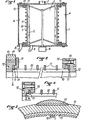
- a screen purifier of the type to which the invention relates comprises an external casing 1 containing a cylindrical screen 2 separating chambers 3 and 4 and a finned rotor 5 driven by the motor 6.
- centrifugal purifier comprising a pulp inlet 7, an accepted pulp outlet 8 and a refusal discharge orifice 9, but, of course, the invention also relates to a centripetal purifier.
- the screen 2 is of the type with longtudinal bars 10 assembled by means of cross-members 11 in the form of a circle, for example by welding.
- the screen 2 is mounted at each end by means of a crown 12 and a counter-crown 13 enclosing a cross member 11 while leaving a clearance between the bars 10 and the crowns 12 and 13.
- This clearance must be mainly provided at 14 along the longitudinal faces or edges of the bars 10 and will preferably be of the order of 0.5 to 1 millimeter. Said clearance may be lower between the end faces 16 of the bars 10 and the rings 12.
- the assemblies of the crowns 12 and 13 between them will for example be carried out by screwing 15 or bolting.
- the end crosspieces 11 are not necessarily placed in line with the end faces 16 of the bars, which may protrude slightly as soon as the intended play is maintained over their entire length.
- the invention applies not only to the case of sieves produced by welding bars 10 on crosspieces 11 in the form of circles, but also when the assembly is carried out without welding as provided for in the patent application French No. 8,417,189 filed on November 12, 1984 in the name of the plaintiff; in fact, the same problem arises when assembling the end rings for the sieves produced according to this request.
- the invention also relates to sieve slits mounted in their end rings according to the invention, these sieves being intended to be themselves mounted in purifiers, filing cabinets or similar devices.
Landscapes
- Chemical & Material Sciences (AREA)
- Chemical Kinetics & Catalysis (AREA)
- Engineering & Computer Science (AREA)
- Manufacturing & Machinery (AREA)
- Mechanical Engineering (AREA)
- Paper (AREA)
- Combined Means For Separation Of Solids (AREA)
- Filtration Of Liquid (AREA)
- Filtering Materials (AREA)
- Storage Of Web-Like Or Filamentary Materials (AREA)
- Apparatus Associated With Microorganisms And Enzymes (AREA)
- Crystals, And After-Treatments Of Crystals (AREA)
- Silicon Compounds (AREA)
- Filtering Of Dispersed Particles In Gases (AREA)
- Memory System Of A Hierarchy Structure (AREA)
Description
- On sait que de nombreux épurateurs de pâte à papier comportent des tamis, généralement de forme cylindrique, réalisée en tôle d'acier inoxydable et dont les perforations sont soit des fentes, soit des trous.
- La réalisation de fentes étroites (quelques dixièmes de millimètres), de section évasée, dans une tôle d'acier inoxydable de 5 à 6 mm d'épaisseur peut se faire par fraisage. Les tamis donnent satisfaction, mais leur prix de revient est très élevé.
- On a donc cherché d'autres moyens, notamment par soudage ou assemblage de barrettes longitudinales sur des traverses en forme de cercles.
- Cependant avec des tamis ainsi réalisés, on rencontre des difficultés à l'assemblage du tamis sur les couronnes d'extrémité qui viennent le centrer et le maintenir dans l'appareil. En effet, cet assemblage est généralement effectué par soudure des extrémités des barrettes sur les couronnes et l'on obseerve des ruptures de barrettes ou de soudures qui mettent rapidement l'appareil hors détat de fonctionner. Un exemple de réalisation de tels tamis est décrit au brevet US-A-4155841.
- L'invention a pour but de résoudre ces inconvénients et elle se rapporte au mode de montage du tamis dans les couronnes d'extrémité.
- L'invention a pour objet un tamis cylindrique pour épurateur réalisé au moyen de barrettes longitudinales assemblées côte à côte sur des traverses en forme de cercle, et comportant à chaque extrémité une couronne de montage, caractérisé en ce qu'il comporte à chaque extrémité une contre-couronne assemblée à la couronne par vissage en enserrant sans jeu une traverse terminale en forme de cercle, tout en laissant un jeu entre les barrettes et les couronne et contre-couronne.
- L'invention est encore remarquable par le fait que le jeu est de l'ordre de 0,5 à 1 millimètre le long des parties longitudinales des barrettes en regard des couronne et contre-couronne.
- L'invention a encore pour objet un épurateur comprenant un tamis cylindrique selon les définitions précédentes.
- Cette disposition extrêmement simple a permis de façon surprenante d'éliminer les ruptures de barettes ou de soudures.
- L'explication de ce résultat semble être que la longévité et la résistance à l'usage d'un tel tamis exigent que les barrettes conservent leur flexibilité et leur souplesse sur toute leur longueur et notamment aux points de fixation sur les couronnes.
- En effet, dans les épurateurs de ce type, il est généralement prévu des rotors à ailettes ou "foils" qui se déplacent à proximité du tamis en vue d'assurer son nettoyage et débouchage permanent par création de dépressions et surpressions alternées. Du fait de la rotation de ce rotor, les barrettes subissent des efforts de flexion alternés ainsi que des efforts tangentiels importants qui sont transmis aux extrémités des barrettes et provoquent les ruptures de soudures ou de barrettes, lorsque celles-ci sont fixées par soudure sur une couronne d'extrémité.
- Le montage objet de l'invention, du fait qu'il laisse aux extrémités des barrettes en libre jeu par rapport aux couronnes, conserve la flexibilité des barrettes sur toute leur longueur, tandis que le centrage et le maintien du tamis sont réalisés par l'intermédiaire des traverses d'extrémité en forme de cercles qui, elles ne sont pas soumises aux mêmes efforts ou aux mêmes déformations.
- Toutefois, l'invention n'est pas limitée à cette explication qui n'a qu'une valeur d'hypotèse.
- L'invention est illustrée par le dessin joint sur lequel:
- La figure 1 est une vue en coupe axiale d'un épurateur muni des dispositions de l'invention;
- La figure 2 est une vue de détail du montage des couronnes d'extrémité, en coupe axiale;
- La figure 3 est une vue en coupe partielle selon A - A de la figure 2;
- La figure 4 est une variante de la figure 2.
- En se reportant à la figure 1, on voit qu'un épurateur à tamis du type auquel se rapporte l'invention comporte une enveloppe externe 1 contenant un tamis cylindrique 2 séparant des chambres 3 et 4 et un rotor à ailettes 5 entraîné par le moteur 6.
- Dans l'exemple représenté, il s'agit d'un épurateur centrifuge comportant une entrée de pâte 7, une sortie de pâte acceptée 8 et un orifice de décharge des refus 9, mais, bien entendu, l'invention se rapporte aussi bien à un épurateur centripète.
- Le tamis 2 est du type à barrettes longtudinales 10 assemblées au moyen de traverses 11 en forme de cercle, par exemple par soudage.
- Conformément à l'invention (figures 2,3,4) le tamis 2 est monté à chaque extrémité au moyen d'une couronne 12 et d'une contre-couronne 13 enserrant une traverse 11 tout en laissant un jeu entre les barrettes 10 et les couronnes 12 et 13. Ce jeu doit être principalement prévu en 14 le long des faces ou arêtes longitudinales des barrettes 10 et sera de préférence de l'ordre de 0,5 à 1 millimètre. Ledit jeu peut être plus faible entre les faces terminales 16 des barrettes 10 et les couronnes 12.
- L'assemblages des couronnes 12 et 13 entre- elles sera par exemple réalisé par vissage 15 ou boulonnage.
- Comme représenté dans la variante de la figure 4, les traverses d'extrémité 11 ne sont pas nécessairement placées au droit des faces terminales 16 des barrettes, lesquelles peuvent déborder légèrement dès lors que le jeu prévu maintenu sur toute leur longuer.
- L'invention s'applique non seulement au cas tamis réalisés par soudage de barrettes 10 sur des traverses 11 en forme de cercles, mais également lorsque l'assemblage est réalisé sans soudure comme prévu à la demande de brevet français n° 8 417 189 déposé le 12 novembre 1984 au nom de la demanderesse; en effet, le même problème se pose à l'assemblage des couronnes d'extrémité pour les tamis réalisés selon cette demande.
- L'invention vise également les tamis à fentes montés dans leurs couronnes d'extrémité selon l'invention, ces tamis étant destinés à être eux- mêmes montés dans des épurantes, classeurs ou appareils analogues.
- Dans les figures 2 et 3, on a représenté 17 des pattes fixées sur la couronne 12 et destinées au montage du tamis dans l'epurateur.
Claims (3)
Priority Applications (1)
| Application Number | Priority Date | Filing Date | Title |
|---|---|---|---|
| AT85402028T ATE40299T1 (de) | 1984-11-12 | 1985-10-21 | Siebe fuer die pulpreinigung und mit diesen sieben versehene siebe. |
Applications Claiming Priority (2)
| Application Number | Priority Date | Filing Date | Title |
|---|---|---|---|
| FR8417189 | 1984-11-12 | ||
| FR8417189A FR2572950B1 (fr) | 1984-11-12 | 1984-11-12 | Perfectionnements aux tamis pour epurateurs et a leur mode de fabrication |
Publications (2)
| Publication Number | Publication Date |
|---|---|
| EP0187553A1 EP0187553A1 (fr) | 1986-07-16 |
| EP0187553B1 true EP0187553B1 (fr) | 1989-01-25 |
Family
ID=9309479
Family Applications (2)
| Application Number | Title | Priority Date | Filing Date |
|---|---|---|---|
| EP85402028A Expired EP0187553B1 (fr) | 1984-11-12 | 1985-10-21 | Perfectionnements aux tamis à fentes pour l'épuration de pâte à papier et aux épurateurs munis de ces tamis |
| EP85402055A Expired EP0182688B1 (fr) | 1984-11-12 | 1985-10-23 | Perfectionnements aux tamis pour épurateurs et à leur mode de fabrication |
Family Applications After (1)
| Application Number | Title | Priority Date | Filing Date |
|---|---|---|---|
| EP85402055A Expired EP0182688B1 (fr) | 1984-11-12 | 1985-10-23 | Perfectionnements aux tamis pour épurateurs et à leur mode de fabrication |
Country Status (9)
| Country | Link |
|---|---|
| US (1) | US4846971A (fr) |
| EP (2) | EP0187553B1 (fr) |
| JP (2) | JPH0653999B2 (fr) |
| AT (2) | ATE40299T1 (fr) |
| CA (1) | CA1265753A (fr) |
| DE (2) | DE3567812D1 (fr) |
| ES (2) | ES296317Y (fr) |
| FI (2) | FI78519C (fr) |
| FR (1) | FR2572950B1 (fr) |
Families Citing this family (60)
| Publication number | Priority date | Publication date | Assignee | Title |
|---|---|---|---|---|
| FI77481C (fi) * | 1985-05-29 | 1989-03-10 | Ahlstroem Oy | Sil. |
| FR2612081B1 (fr) * | 1987-03-13 | 1991-02-08 | Lamort E & M | Perfectionnement aux tamis pour epurateur et a leur mode de fabrication |
| DE3716434C1 (de) * | 1987-05-16 | 1988-12-08 | Hans-Georg Huber | Vorrichtung zum Entfernen von Rechen- und/oder Siebgut aus in einem Gerinne stroemender Fluessigkeit |
| JPH02501491A (ja) * | 1987-06-11 | 1990-05-24 | エイ.アフルストロム コーポレーション | パルプ濾過装置 |
| WO1988010335A1 (fr) * | 1987-06-26 | 1988-12-29 | A. Ahlstrom Corporation | Appareil pour tamiser la pate de cellulose et procede de tamisage d'une suspension de pate |
| DE3816152A1 (de) * | 1987-11-14 | 1989-11-23 | Voith Gmbh J M | Siebkorb und verfahren zu dessen herstellung |
| FR2623419B1 (fr) * | 1987-11-25 | 1990-03-23 | Combustion Eng Europ | Appareil de filtrage autonettoyant |
| DE68903255T2 (de) * | 1988-08-12 | 1993-05-19 | Lamort E & M | Sieb zur reinigung und klassifizierung von papierstoffbrei. |
| JPH0281607U (fr) * | 1988-12-07 | 1990-06-25 | ||
| EP0383622A3 (fr) * | 1989-02-16 | 1990-12-19 | Tom Holdings Limited | Procédé filtrant |
| DE3927748C2 (de) * | 1989-08-23 | 1994-03-10 | Voith Gmbh J M | Verfahren zum Herstellen eines Siebkorbes sowie nach diesem Verfahren hergestellter Siebkorb |
| DE3942591A1 (de) * | 1989-12-22 | 1991-06-27 | Voith Gmbh J M | Siebkorb |
| US5047148A (en) * | 1990-04-24 | 1991-09-10 | Koichi Arai | Retained wire filter element |
| DE4104615A1 (de) * | 1991-02-15 | 1992-08-20 | Voith Gmbh J M | Siebkorb |
| DE4121897A1 (de) * | 1991-07-02 | 1993-01-07 | Fiedler Heinrich Gmbh | Siebelement |
| DE4121896A1 (de) * | 1991-07-02 | 1993-01-07 | Fiedler Heinrich Gmbh | Siebelement |
| ATE154890T1 (de) * | 1992-02-07 | 1997-07-15 | Votech Filter Gmbh | Filterpatrone |
| DE4224727A1 (de) * | 1992-07-27 | 1994-02-03 | Voith Gmbh J M | Siebkorb |
| SE500893C2 (sv) * | 1993-02-10 | 1994-09-26 | Sunds Defibrator Ind Ab | Trycksilanordning |
| SE501273C2 (sv) * | 1993-05-14 | 1994-12-19 | Knutsilplaotar Ab | Siltrumma för silning av suspensioner av lignocellulosahaltigt fibermaterial |
| DE4435538C2 (de) * | 1994-10-05 | 1996-10-02 | Voith Gmbh J M | Verfahren zur Herstellung eines Flachsiebes |
| US5823355A (en) * | 1995-03-29 | 1998-10-20 | Beloit Technologies, Inc. | Fibresaver screen basket support |
| FI100344B (fi) * | 1995-11-28 | 1997-11-14 | Ahlstrom Machinery Oy | Menetelmä lankaseulatuotteen valmistamiseksi ja lankaseulatuote |
| EP0868237B1 (fr) * | 1995-12-14 | 2000-04-12 | Attlington Investments Limited | Procede de production d'un profile metallique |
| US5791495A (en) * | 1996-03-11 | 1998-08-11 | Beloit Technologies, Inc. | Paper pulp screen cylinder |
| DE19620051A1 (de) * | 1996-05-18 | 1997-11-20 | Voith Sulzer Stoffaufbereitung | Vorrichtung zum Sortieren von faserstoffhaltiger Suspension |
| EP0808941B1 (fr) * | 1996-05-24 | 2001-12-12 | Voith Sulzer Stoffaufbereitung GmbH | Procédé de fabrication d'un appareil de tamisage à ouvertures en forme de fentes et appareil de tamisage produit par ce procédé |
| US7188733B2 (en) * | 1996-10-03 | 2007-03-13 | Advanced Fiber Technologies (Aft) Trust | Screening device, such as a screen cylinder, and method of manufacture of the screening device |
| CN1080350C (zh) * | 1996-10-03 | 2002-03-06 | Cae筛板公司 | 筛浆装置、例如筛筒以及筛浆装置的制造方法 |
| US5954956A (en) * | 1997-07-22 | 1999-09-21 | J&L Fiber Services | Modular screen cylinder and a method for its manufacture |
| US6165370A (en) * | 1998-01-21 | 2000-12-26 | Voith Sulzer Paper Technology North America, Inc. | Pressure screen monitoring apparatus and method |
| FR2786480A1 (fr) * | 1998-12-01 | 2000-06-02 | Polydis Ind | Dispositif de traitement biologique des eaux industrielles usees, notamment de rejets vinicoles |
| FR2809029B1 (fr) * | 2000-05-16 | 2002-06-21 | Johnson Filtration Systems | Procede de fabrication d'un panier mecanique de filtration |
| DE10052715A1 (de) * | 2000-10-24 | 2002-05-02 | Fiedler Heinrich Gmbh | Spaltsiebanordnung |
| US6460757B1 (en) | 2000-11-14 | 2002-10-08 | Newscreen As | Apparatus and method for forming slotted wire screens |
| JP2002346430A (ja) * | 2001-05-23 | 2002-12-03 | Mitsubishi Heavy Ind Ltd | スクリーンシリンダの製作方法、スクリーン、および材料ふるい分け装置 |
| SE519079C2 (sv) * | 2001-05-30 | 2003-01-07 | Metso Paper Inc | Sil för silning av massasuspensioner innefattande en stödring med konisk yta |
| DE10148192A1 (de) * | 2001-09-28 | 2003-04-17 | Fiedler Heinrich Gmbh | Spaltsiebanordnung |
| ITVI20040139A1 (it) * | 2004-06-10 | 2004-09-10 | Comer Spa | Metodo per la fabbricazione di cestelli filtranti di fibre in sospensione acquosa e cestello filtrante fabbricato mediante detto metodo |
| US20090020461A1 (en) | 2005-05-09 | 2009-01-22 | Filtration Fibrewall Inc. | Screen Basket with Replaceable Profiled Bars |
| DE102006007660A1 (de) * | 2006-02-22 | 2007-08-23 | Voith Patent Gmbh | Verfahren zur Herstellung einer rotations-symmetrischen, insbesondere zylindrischen Siebvorrichtung |
| ITVI20070209A1 (it) * | 2007-07-31 | 2009-02-01 | Comer Spa | Cestello filtrante perfezionato per fibre in sospensione acquosa |
| JP5465181B2 (ja) | 2007-11-14 | 2014-04-09 | フィルトレーション・ファイバーウォール・インコーポレーテッド | スクリーンバスケット |
| US20090211965A1 (en) * | 2008-02-21 | 2009-08-27 | Weatherford/Lamb, Inc. | Arrangement for splicing panels together to form a cylindrical screen |
| US8028691B2 (en) * | 2008-10-27 | 2011-10-04 | Johnson Screens, Inc. | Passive solar wire screens for buildings |
| AT509855B1 (de) * | 2010-07-29 | 2011-12-15 | Ife Aufbereitungstechnik Gmbh | Sieb |
| US9023456B2 (en) | 2011-03-18 | 2015-05-05 | Bilfinger Water Technologies, Inc. | Profiled wire screen for process flow and other applications |
| BE1020768A3 (nl) * | 2012-06-29 | 2014-04-01 | Unislot Nv | Aangepaste profieldraad voor filterelementen. |
| DE212015000246U1 (de) | 2014-10-14 | 2017-05-19 | Aikawa Fiber Technologies Trust | Siebzylinder |
| WO2017004410A1 (fr) * | 2015-06-30 | 2017-01-05 | Bilfinger Water Technologies, Inc. | Appareil de serrage de crible à tambour |
| CN107670356A (zh) * | 2017-11-03 | 2018-02-09 | 绥阳县双龙纸业有限公司 | 一种用于纸浆的过滤装置 |
| DE102017127562A1 (de) * | 2017-11-22 | 2019-05-23 | Voith Patent Gmbh | Sieb |
| DE102017129752A1 (de) * | 2017-12-13 | 2019-06-13 | Voith Patent Gmbh | Siebherstellverfahren |
| US11846070B2 (en) | 2019-08-16 | 2023-12-19 | Aikawa Fiber Technologies Oy | Screen cylinder |
| FI20195686A1 (en) | 2019-08-16 | 2021-02-17 | Aikawa Fiber Tech Oy | SILTRUMMA |
| DE102019128878B3 (de) | 2019-10-25 | 2020-07-30 | Voith Patent Gmbh | Siebzylinder |
| CN111069032B (zh) * | 2020-01-14 | 2021-04-20 | 河北省环保产品质量监督检验研究院 | 实验室用土壤筛分仪 |
| CN112191023A (zh) * | 2020-11-02 | 2021-01-08 | 石家庄天诚特种设备有限公司 | 一种工业条缝筛网及其激光加工工艺 |
| WO2022263093A1 (fr) | 2021-06-15 | 2022-12-22 | Andritz Fiedler Gmbh | Ensemble barre profilée |
| DE102022112037A1 (de) | 2021-06-15 | 2022-12-15 | Andritz Fiedler Gmbh | Profilstabanordnung |
Family Cites Families (22)
| Publication number | Priority date | Publication date | Assignee | Title |
|---|---|---|---|---|
| GB191016779A (en) * | 1910-07-14 | 1911-02-02 | William Brown | Improvements in Filtering Apparatus for Milk. |
| GB154612A (en) * | 1919-12-01 | 1921-08-25 | Ladislas Penkala | Improvements in straining filters |
| US1527404A (en) * | 1920-02-13 | 1925-02-24 | Lucius A Haller | Sifting and mixing machine |
| FR552950A (fr) * | 1922-06-15 | 1923-05-09 | Procédé pour la production de surfaces à capillarité augmentée | |
| FR672494A (fr) * | 1928-04-12 | 1929-12-28 | Louis Herrmann | Tamis pour le tamisage fin ou le filtrage |
| US1988402A (en) * | 1932-11-14 | 1935-01-15 | Charles Walmsley And Company L | Reticulate drum or cylinder of paper making and like machines |
| US2488009A (en) * | 1948-03-01 | 1949-11-15 | Edward F Goebel | Fuel oil filter |
| FR1055784A (fr) * | 1950-06-30 | 1954-02-22 | Buss Ag | Appareil à fentes et couteaux pour le traitement des liquides |
| US2747741A (en) * | 1952-08-21 | 1956-05-29 | Gulf Research Development Co | Device for continuous removal of solids from fluids |
| US2803172A (en) * | 1953-01-16 | 1957-08-20 | Trotman William Edwin Knowles | Cylinder machine mold |
| US2707905A (en) * | 1953-04-01 | 1955-05-10 | Wilfred F Mathewson | Pulp screen |
| FR1118891A (fr) * | 1955-01-06 | 1956-06-12 | Ossature de support pour appareil servant à la fabrication de papier et de carton imprégnés d'une matière de charge | |
| FR1271262A (fr) * | 1960-07-29 | 1961-09-08 | Olier Sa Ets A | Cage perfectionnée pour presse d'extraction d'un liquide notamment de l'huile des olives |
| US3308594A (en) * | 1963-06-10 | 1967-03-14 | United States Steel Corp | Slotted panel assembly |
| US3389451A (en) * | 1965-12-20 | 1968-06-25 | Air Preheater | Method of making an interlocking strip structure |
| BE723425A (fr) * | 1966-11-14 | 1969-04-16 | ||
| GB1258090A (fr) * | 1969-05-19 | 1971-12-22 | ||
| US3770129A (en) * | 1972-05-15 | 1973-11-06 | Harvey W Res Corp | Manually flexible blood filter |
| US4155841A (en) * | 1977-03-22 | 1979-05-22 | The Black Clawson Company | High turbulence screen |
| SE427124B (sv) * | 1980-01-28 | 1983-03-07 | Celleco Ab | Anordning for silning av fibermassasuspensioner |
| US4410424A (en) * | 1980-05-02 | 1983-10-18 | The Black Clawson Company | Screening apparatus for paper making stock |
| US4318805A (en) * | 1980-09-29 | 1982-03-09 | Bird Machine Company, Inc. | Screening apparatus |
-
1984
- 1984-11-12 FR FR8417189A patent/FR2572950B1/fr not_active Expired
-
1985
- 1985-10-21 EP EP85402028A patent/EP0187553B1/fr not_active Expired
- 1985-10-21 DE DE8585402028T patent/DE3567812D1/de not_active Expired
- 1985-10-21 AT AT85402028T patent/ATE40299T1/de active
- 1985-10-23 AT AT85402055T patent/ATE34670T1/de not_active IP Right Cessation
- 1985-10-23 DE DE8585402055T patent/DE3562980D1/de not_active Expired
- 1985-10-23 EP EP85402055A patent/EP0182688B1/fr not_active Expired
- 1985-11-04 ES ES1985296317U patent/ES296317Y/es not_active Expired
- 1985-11-07 ES ES1985296322U patent/ES296322Y/es not_active Expired
- 1985-11-08 CA CA000494902A patent/CA1265753A/fr not_active Expired - Lifetime
- 1985-11-08 FI FI854407A patent/FI78519C/fi not_active IP Right Cessation
- 1985-11-11 FI FI854430A patent/FI78520C/fi not_active IP Right Cessation
- 1985-11-12 JP JP60252127A patent/JPH0653999B2/ja not_active Expired - Lifetime
- 1985-11-12 JP JP60252128A patent/JPS61119792A/ja active Pending
-
1988
- 1988-02-16 US US07/157,180 patent/US4846971A/en not_active Expired - Fee Related
Also Published As
| Publication number | Publication date |
|---|---|
| ES296322Y (es) | 1988-02-16 |
| FI854430A0 (fi) | 1985-11-11 |
| FI78519B (fi) | 1989-04-28 |
| EP0187553A1 (fr) | 1986-07-16 |
| EP0182688A1 (fr) | 1986-05-28 |
| FR2572950B1 (fr) | 1987-01-23 |
| FR2572950A1 (fr) | 1986-05-16 |
| FI854430L (fi) | 1986-05-13 |
| JPS61119792A (ja) | 1986-06-06 |
| JPS61119793A (ja) | 1986-06-06 |
| FI78520B (fi) | 1989-04-28 |
| ES296322U (es) | 1987-08-01 |
| US4846971A (en) | 1989-07-11 |
| JPH0653999B2 (ja) | 1994-07-20 |
| ATE34670T1 (de) | 1988-06-15 |
| CA1265753A (fr) | 1990-02-13 |
| EP0182688B1 (fr) | 1988-06-01 |
| FI78520C (fi) | 1989-08-10 |
| ES296317Y (es) | 1988-02-16 |
| FI854407L (fi) | 1986-05-13 |
| DE3567812D1 (en) | 1989-03-02 |
| FI78519C (fi) | 1989-08-10 |
| DE3562980D1 (en) | 1988-07-07 |
| ES296317U (es) | 1987-08-01 |
| ATE40299T1 (de) | 1989-02-15 |
| FI854407A0 (fi) | 1985-11-08 |
Similar Documents
| Publication | Publication Date | Title |
|---|---|---|
| EP0187553B1 (fr) | Perfectionnements aux tamis à fentes pour l'épuration de pâte à papier et aux épurateurs munis de ces tamis | |
| MX2010005202A (es) | Canasta de filtro. | |
| EP3606640B1 (fr) | Élément filtrant et agencement de filtre ayant des filtres de fluide et un élément filtrant | |
| CA2311154C (fr) | Tamis cylindrique, notamment pour la pate a papier | |
| EP0159930A1 (fr) | Stator pour petits moteurs électriques | |
| FR2552165A1 (fr) | Installation pour le blocage axial et peripherique de composants de carter statiques de machines a fluide | |
| FR2609765A1 (fr) | Disque de frein divise axialement, notamment pour vehicules ferroviaires | |
| SU1716957A3 (ru) | Фильтрующа секци вращательного фильтра | |
| EP1757796A2 (fr) | Compresseur comportant une pluralité de caissons reconstituant un volume annulaire de séparation de flux dans une turbomachine | |
| EP0707109B1 (fr) | Perfectionnements aux tamis d'épuration, notamment pour la pâte à papier | |
| EP0284494B1 (fr) | Dispositif d'assemblage de pièces de bois de construction | |
| FR3090234A1 (fr) | Rotor à arbre non traversant et machine électrique tournante associée | |
| EP0358731A1 (fr) | Ventilateur axial. | |
| EP0453348A1 (fr) | Tamis pour épurateur et classificateur de pâte à papier | |
| CN212467493U (zh) | 一种过滤装置及其过滤芯 | |
| FR2524079A1 (fr) | Groupe moto-pompe pour des installations de chauffage et d'eau industrielle | |
| FR2643268A1 (fr) | Appareil de traitement de fluides a membrane plane | |
| FR2480814A1 (fr) | Tamis classeur pour l'industrie du papier | |
| FR2666460A1 (fr) | Structure de noyau de rotor pour une machine tournante electromagnetique. | |
| DE20021673U1 (de) | Baugruppe für ein Fahrzeuginsassenrückhaltesystem | |
| FR2723772A1 (fr) | Dispositif de volant moteur a montage modulaire | |
| JP3180662U (ja) | ワイヤーストレーナー | |
| EP0115339B1 (fr) | Enveloppe tubulaire pour électrode d'accumulateur | |
| FR2651024A1 (fr) | Dispositif d'assemblage d'elements longitudinaux | |
| CA2483807C (fr) | Disque filtrant avec segments de panneau |
Legal Events
| Date | Code | Title | Description |
|---|---|---|---|
| PUAI | Public reference made under article 153(3) epc to a published international application that has entered the european phase |
Free format text: ORIGINAL CODE: 0009012 |
|
| AK | Designated contracting states |
Kind code of ref document: A1 Designated state(s): AT BE CH DE FR GB IT LI NL SE |
|
| 17P | Request for examination filed |
Effective date: 19860804 |
|
| 17Q | First examination report despatched |
Effective date: 19871111 |
|
| GRAA | (expected) grant |
Free format text: ORIGINAL CODE: 0009210 |
|
| AK | Designated contracting states |
Kind code of ref document: B1 Designated state(s): AT BE CH DE FR GB IT LI NL SE |
|
| PG25 | Lapsed in a contracting state [announced via postgrant information from national office to epo] |
Ref country code: NL Effective date: 19890125 Ref country code: AT Effective date: 19890125 |
|
| REF | Corresponds to: |
Ref document number: 40299 Country of ref document: AT Date of ref document: 19890215 Kind code of ref document: T |
|
| REF | Corresponds to: |
Ref document number: 3567812 Country of ref document: DE Date of ref document: 19890302 |
|
| GBT | Gb: translation of ep patent filed (gb section 77(6)(a)/1977) | ||
| ITF | It: translation for a ep patent filed | ||
| NLV1 | Nl: lapsed or annulled due to failure to fulfill the requirements of art. 29p and 29m of the patents act | ||
| PG25 | Lapsed in a contracting state [announced via postgrant information from national office to epo] |
Ref country code: GB Effective date: 19891021 |
|
| PG25 | Lapsed in a contracting state [announced via postgrant information from national office to epo] |
Ref country code: SE Effective date: 19891022 |
|
| PG25 | Lapsed in a contracting state [announced via postgrant information from national office to epo] |
Ref country code: LI Effective date: 19891031 Ref country code: CH Effective date: 19891031 Ref country code: BE Effective date: 19891031 |
|
| PLBE | No opposition filed within time limit |
Free format text: ORIGINAL CODE: 0009261 |
|
| STAA | Information on the status of an ep patent application or granted ep patent |
Free format text: STATUS: NO OPPOSITION FILED WITHIN TIME LIMIT |
|
| 26N | No opposition filed | ||
| BERE | Be: lapsed |
Owner name: E. + M. LAMORT Effective date: 19891031 |
|
| GBPC | Gb: european patent ceased through non-payment of renewal fee | ||
| PG25 | Lapsed in a contracting state [announced via postgrant information from national office to epo] |
Ref country code: FR Effective date: 19900629 |
|
| REG | Reference to a national code |
Ref country code: CH Ref legal event code: PL |
|
| PG25 | Lapsed in a contracting state [announced via postgrant information from national office to epo] |
Ref country code: DE Effective date: 19900703 |
|
| REG | Reference to a national code |
Ref country code: FR Ref legal event code: ST |
|
| EUG | Se: european patent has lapsed |
Ref document number: 85402028.6 Effective date: 19900706 |