EP0187555A1 - Wellenlötmaschine - Google Patents
Wellenlötmaschine Download PDFInfo
- Publication number
- EP0187555A1 EP0187555A1 EP85402210A EP85402210A EP0187555A1 EP 0187555 A1 EP0187555 A1 EP 0187555A1 EP 85402210 A EP85402210 A EP 85402210A EP 85402210 A EP85402210 A EP 85402210A EP 0187555 A1 EP0187555 A1 EP 0187555A1
- Authority
- EP
- European Patent Office
- Prior art keywords
- nozzle
- cam
- wave
- wall
- adjustable
- Prior art date
- Legal status (The legal status is an assumption and is not a legal conclusion. Google has not performed a legal analysis and makes no representation as to the accuracy of the status listed.)
- Withdrawn
Links
Images

Classifications
-
- B—PERFORMING OPERATIONS; TRANSPORTING
- B23—MACHINE TOOLS; METAL-WORKING NOT OTHERWISE PROVIDED FOR
- B23K—SOLDERING OR UNSOLDERING; WELDING; CLADDING OR PLATING BY SOLDERING OR WELDING; CUTTING BY APPLYING HEAT LOCALLY, e.g. FLAME CUTTING; WORKING BY LASER BEAM
- B23K3/00—Tools, devices or special appurtenances for soldering, e.g. brazing, or unsoldering, not specially adapted for particular methods
- B23K3/06—Solder feeding devices; Solder melting pans
- B23K3/0646—Solder baths
- B23K3/0653—Solder baths with wave generating means, e.g. nozzles, jets, fountains
-
- B—PERFORMING OPERATIONS; TRANSPORTING
- B23—MACHINE TOOLS; METAL-WORKING NOT OTHERWISE PROVIDED FOR
- B23K—SOLDERING OR UNSOLDERING; WELDING; CLADDING OR PLATING BY SOLDERING OR WELDING; CUTTING BY APPLYING HEAT LOCALLY, e.g. FLAME CUTTING; WORKING BY LASER BEAM
- B23K2101/00—Articles made by soldering, welding or cutting
- B23K2101/36—Electric or electronic devices
- B23K2101/42—Printed circuits
Definitions
- the present invention relates to a device for generating a solder wave for a machine for wave soldering of components arranged on printed circuit boards running through the machine, this device being equipped with a nozzle which comprises a elongated shape with converging walls and a mouth opening at its top and extending below the path of travel of the printed circuits, over the entire width thereof, this nozzle, connected to a solder supply tank liquid, being capable of emitting an upward current of solder forming a wave which comes to lick the underside of the printed circuits and the tails of components which project from it.
- the object of the present invention is to improve the reliability of manufacture in the wave welding process by allowing the shape of the wave to be precisely shaped at will in each particular case.
- the degree of throttling that said mouth comprises is varied. This allows, for a given flow rate of the solder flowing through the nozzle, to adjust the speed of ejection of the solder and, thus, to make the wave take an contour of optimal shape.
- the adjustment of the passage section of the nozzle is preferably carried out by adjusting the angle formed between them by the converging walls of the nozzle, and this advantageously using an adjustment means. accessible outside the liquid solder mass, so that the adjustment of the nozzle is possible in all circumstances, and in particular while it is in operation.
- one of the walls of the nozzle is movable and, for said adjustment, angularly movable, relative to the other wall, around a pivot axis located along its lower edge , which axis can be defined by a flexible zone of the movable wall, the angular displacement of said wall being effected by the bending of this zone.
- the adjustment means can then be constituted by a rotary cam acting on one of the faces of the movable wall, the latter being resiliently biased against said cam.
- the cam In order not to disturb the flow of the weld in the nozzle, the cam should be located outside of the latter.
- the restoring force of the movable wall can be provided by its zone containing the virtual pivot axis, this zone being elastically flexible.
- the aforementioned plate is articulated to the rear wall of the nozzle and is adjustable angularly around its axis of articulation using an adjustment means.
- this adjustment means should be accessible outside the liquid solder mass. It can likewise be constituted by a rotary cam, which supports the plate.
- the structure is preferably such that the dihedral having for its edge the axis of articulation and defined by the contact line of the cam and of the plate and by the pivot axis of the movable wall of the nozzle is substantially straight. In this way, the adjustment of the nozzle reacts little on that of the plate in question.
- a substantially vertical orientation flap forming, with a surface for guiding the weld current flowing upstream, an adjustable opening interval into which said weld current falls. Adjusting the position of this flap makes it possible to vary the constriction offered by said opening and, thereby, to adjust the speed with which said upstream solder current attacks the underside of the printed circuits and the tails of components which protrude. It is thus possible to measure the blocking force of the tails of components in the printed circuits, as well as the vacuum within the solder which tends to retain by suction the veil possibly present on the surface of the molten metal mass.
- the aforementioned flap is angularly movable, relative to the guide surface, around a pivot axis located along its upper edge, and it is adjustable in orientation using an adjustment means, which is advantageously accessible outside the liquid solder mass, while it can also be constituted by a rotary cam, which acts on the face of the flap opposite the guide surface, the flap being biased elastically against the cam .
- the corresponding return force can be provided by an elastically flexible zone which the flap has between its line of contact with the cam and its pivot axis, the latter being materialized by a fixed rod to which the upper edge of the flap is made integral.
- the weld circulating in the device is kept in fusion by heating resistors arranged inside the reserve tank.
- the temperature of the solder forming the wave tends to drop compared to that of the solder contained in the tank.
- said device forms, with the adjustable nozzle and the other adjustable elements that may be provided, as well as the or the corresponding adjustment means, and with the auxiliary heating element or elements with which it is optionally provided, a structural unit removably mounted on the weld reserve tank.
- Figure 1 shows, in section through a vertical plane parallel to the running direction of the printed circuits, a device according to the invention mounted on the soldering tank of a wave soldering machine.
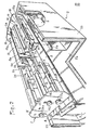
- Figure 2 shows, in perspective with cutaway, the device of Figure 1 presented above the soldering tank.
- the figures show a device 1 designed to create a wave of liquid solder in a wave soldering machine for printed circuits.
- This device constitutes a unitary assembly which is mounted on a tank 2 for supplying liquid solder.
- the tank 2 the bottom 2a and the walls 2b of which are heat-insulated, is equipped, in known manner, with electric heating resistors (not shown) ensuring the melting of the solder mass it contains, and a pump (also not shown) for discharging the liquid solder, with a determined flow rate, via a conduit 5 towards the device 1.
- the latter thus supplied, gives rise to a solder wave 6 which comes to lick the underside of the printed circuits running past above the device 1 following a rectilinear path 7 slightly ascending.
- the soldering, wetting the metallized parts of the printed circuits and the tails of the components which have been previously arranged on said circuits, ensures mutual soldering.
- the device 1 and its supply conduit 5 extend, transverse to the direction of travel of the printed circuits, over the entire width of the path that these follow.
- the device 1 comprises a base plate 8 which is fixed on a top edge 5a of the conduit 5 by means of screws 9 taking place in tubular spacers 10 welded to said plate.
- the latter comprises over almost its entire length a wide flat 11, the corresponding part 8a of the plate being folded upwards at 90 to form one of the walls of a nozzle 12, the other wall of which is constituted by a plate 13 fixed to the plate 8 and arranged opposite the wall 8a.
- the nozzle 12, receiving the welding current from the conduit 5 via the puncture 11, generates the welding wave 6.
- the front wall 8a of the nozzle 12 (according to the direction of travel F of the printed circuits), planar, is vertical, its rear wall 13, also planar, is oblique, moving closer to the wall 8a from its base to its top, so that the nozzle 12 is a converging nozzle offering a mouth 12a of width less than the width of the puncture 11. It is further noted that the mean direction of the nozzle 12 is oriented towards the side from which the printed circuits arrive along arrow F.
- the oblique orientation of the rear wall 13 is adjustable.
- This wall is constituted by an elastically deformable sheet, welded flat on the plate 8 and straightening upwards in a curved zone 13a to form the actual wall of the nozzle 12.
- This wall is supported elastically, by its opposite face at the wall, against a cam 14 which extends outside the nozzle, along its length, between two side cheeks 15 welded vertically to the ends of the plate 8.
- a hexagonal head 14a disposed outside one of the cheeks 15 the cam 14 can be rotated about its eccentric longitudinal axis and, thus, adjust the angular position of the wall 13 around a virtual pivot axis corresponding to its area curved 13a. This adjustment makes it possible to more or less narrow the passage section of the mouth 12a of the nozzle 12.
- the arrangement of the elements is chosen such that the part of the plate resting on the cam 19 is substantially perpendicular to the plane of the movable wall 13 of the nozzle, so that , during an adjustment of the nozzle, this part of the plate moves substantially along its own plane.
- the latter made of an elastically deformable sheet, is welded along its edge higher than a fixed rod 23, fixed by embedding in the cheeks 15, and it bears elastically against a cam 24, similar to the cams 14 and 19 and arranged in the same way, which can be actuated in rotation by means of a hexagonal head 24a terminal, close to heads 14a and 19a of the other two cams.
- the cam 14 is immersed in the liquid weld, while the cams 19 and 24 are located outside of the weld mass.
- all three can be controlled while the device is in service to create the welding wave 6, in other words during the operation of the welding machine.
- the device 1 is also provided with two shielded resistors 25, 26 extending between the cheeks 15 in the vicinity of the mouth 12a of the nozzle.
- the purpose of these resistors is to heat the solder in the region of wave 6 where it is subject to significant heat loss.
- the temperature can be controlled either by a thermometric probe 27 or 28, or by an infrared pyrometer 29, controlling the electrical supply of the resistors 25, 26 via a control circuit.
Landscapes
- Engineering & Computer Science (AREA)
- Mechanical Engineering (AREA)
- Molten Solder (AREA)
- Electric Connection Of Electric Components To Printed Circuits (AREA)
Applications Claiming Priority (2)
| Application Number | Priority Date | Filing Date | Title |
|---|---|---|---|
| FR8417448A FR2572969B1 (fr) | 1984-11-15 | 1984-11-15 | Dispositif reglable de generation d'une vague de soudure pour machine de soudage a la vague |
| FR8417448 | 1984-11-15 |
Publications (1)
| Publication Number | Publication Date |
|---|---|
| EP0187555A1 true EP0187555A1 (de) | 1986-07-16 |
Family
ID=9309627
Family Applications (1)
| Application Number | Title | Priority Date | Filing Date |
|---|---|---|---|
| EP85402210A Withdrawn EP0187555A1 (de) | 1984-11-15 | 1985-11-15 | Wellenlötmaschine |
Country Status (3)
| Country | Link |
|---|---|
| EP (1) | EP0187555A1 (de) |
| JP (1) | JPS61126961A (de) |
| FR (1) | FR2572969B1 (de) |
Families Citing this family (5)
| Publication number | Priority date | Publication date | Assignee | Title |
|---|---|---|---|---|
| JPS6478671A (en) * | 1987-09-18 | 1989-03-24 | Tamura Seisakusho Kk | Jet type soldering device |
| JP2757389B2 (ja) * | 1988-09-13 | 1998-05-25 | 松下電器産業株式会社 | 噴流式自動半田付装置 |
| US11389888B2 (en) * | 2020-08-17 | 2022-07-19 | Illinois Tool Works Inc. | Wave solder nozzle with automated exit wing |
| US20250269450A1 (en) * | 2024-02-27 | 2025-08-28 | Illinois Tool Works Inc. | System and method for combined wave solder flow design |
| CN119857991B (zh) * | 2025-03-10 | 2025-08-26 | 哈尔滨东安实业发展有限公司 | 一种分段焊接用环焊前点焊夹具及其使用方法 |
Citations (3)
| Publication number | Priority date | Publication date | Assignee | Title |
|---|---|---|---|---|
| US3119363A (en) * | 1961-09-06 | 1964-01-28 | Gen Electric | Adjustable wave soldering apparatus |
| JPS57142766A (en) * | 1981-02-26 | 1982-09-03 | Sony Corp | Jet type automatic soldering device |
| US4465219A (en) * | 1981-06-02 | 1984-08-14 | Nihon Den-Netsu Keiki Co., Ltd. | Soldering apparatus |
-
1984
- 1984-11-15 FR FR8417448A patent/FR2572969B1/fr not_active Expired
-
1985
- 1985-11-15 EP EP85402210A patent/EP0187555A1/de not_active Withdrawn
- 1985-11-15 JP JP60256507A patent/JPS61126961A/ja active Pending
Patent Citations (3)
| Publication number | Priority date | Publication date | Assignee | Title |
|---|---|---|---|---|
| US3119363A (en) * | 1961-09-06 | 1964-01-28 | Gen Electric | Adjustable wave soldering apparatus |
| JPS57142766A (en) * | 1981-02-26 | 1982-09-03 | Sony Corp | Jet type automatic soldering device |
| US4465219A (en) * | 1981-06-02 | 1984-08-14 | Nihon Den-Netsu Keiki Co., Ltd. | Soldering apparatus |
Non-Patent Citations (1)
| Title |
|---|
| PATENTS ABSTRACTS OF JAPAN, vol. 6, no. 246 (M-176) [1124], 4 décembre 1982; & JP -A - 57 142 766 (SONY K.K.) 03.09.1982 * |
Also Published As
| Publication number | Publication date |
|---|---|
| FR2572969B1 (fr) | 1988-09-09 |
| FR2572969A1 (fr) | 1986-05-16 |
| JPS61126961A (ja) | 1986-06-14 |
Similar Documents
| Publication | Publication Date | Title |
|---|---|---|
| EP0186538A2 (de) | Wellenlötmaschine | |
| FR2702749A1 (fr) | Dispositif de conduite d'une feuille. | |
| FR2659036A1 (fr) | Dispositif de fourniture d'un courant de metal a l'etat fondu pour le formage par projection. | |
| EP0041975B1 (de) | Verbesserte spritzpistole zum warmspritzen von farben | |
| EP0806262A1 (de) | Verfahren und Vorrichtung zum Wellenlöten oder Wellenverzinnen | |
| EP0187555A1 (de) | Wellenlötmaschine | |
| FR2524358A1 (fr) | Dispositif pour le brasage de pieces | |
| FR2608955A1 (fr) | Appareil et procede pour fabriquer des poutres a ame pleine | |
| EP0531501B1 (de) | Entgratverfahren und - vorrichtung, insbesondere für ein in strängen geschnittenes stahlband | |
| FR2683463A1 (fr) | Bec pour tete de douche. | |
| EP0141941A1 (de) | Vorrichtung zum Niederschlagen einer polykristallinen Siliziumschicht auf einem Kohlenstoffband | |
| EP0185566B1 (de) | Lötmaschine | |
| EP3757281B1 (de) | Bügeleisen, das mit einer verdampfungskammer mit zwei elektrischen heizwiderständen ausgestattet ist | |
| FR2638993A1 (fr) | Dispositif de decapage de deux bords de tole metallique a souder | |
| EP0913217B1 (de) | Vorrichtung zum Verteilen von Schlackenpulver und Stranggiessanlage mit einer derartigen Verteilungsvorrichtung | |
| FR2780110A1 (fr) | Oscillateur fluidique, piece destinee a etre incorporee dans un oscillateur fluidique et procede de fabrication d'un tel oscillateur fluidique | |
| FR2587256A1 (fr) | Buse pour machine de soudure a la vague | |
| EP3757280B1 (de) | Bügeleisen, das mit einer verdampfungskammer mit geneigter oberfläche ausgestattet ist | |
| FR2685854A1 (fr) | Mangeoire avicole et installation de distribution d'aliments qui en est equipee. | |
| FR2564492A1 (fr) | Dispositif pour remplir de lessive un recipient collecteur par rotation du tambour d'une machine a laver | |
| FR2587257A1 (fr) | Unite de buse pour machine de soudure a la vague | |
| FR2485363A1 (fr) | Dispositif pour regenerer l'echangeur d'ions d'une machine a laver la vaisselle | |
| FR2632227A1 (fr) | Dispositif pour le soudage a l'arc au plafond sous flux | |
| EP1270131A1 (de) | Vorrichtung zum Wellenlöten von Leiterplatten | |
| EP0278885A1 (de) | Vorrichtung zum Löten von gedruckten Schaltungen auf einen Träger |
Legal Events
| Date | Code | Title | Description |
|---|---|---|---|
| PUAI | Public reference made under article 153(3) epc to a published international application that has entered the european phase |
Free format text: ORIGINAL CODE: 0009012 |
|
| AK | Designated contracting states |
Kind code of ref document: A1 Designated state(s): AT BE CH DE GB IT LI LU NL SE |
|
| STAA | Information on the status of an ep patent application or granted ep patent |
Free format text: STATUS: THE APPLICATION IS DEEMED TO BE WITHDRAWN |
|
| 18D | Application deemed to be withdrawn |
Effective date: 19870119 |
|
| RIN1 | Information on inventor provided before grant (corrected) |
Inventor name: SIMONETTI, JEAN-PIERRE |