EP0187595A2 - Schutzüberzug für elektrolytischen Kondensator - Google Patents
Schutzüberzug für elektrolytischen Kondensator Download PDFInfo
- Publication number
- EP0187595A2 EP0187595A2 EP85402543A EP85402543A EP0187595A2 EP 0187595 A2 EP0187595 A2 EP 0187595A2 EP 85402543 A EP85402543 A EP 85402543A EP 85402543 A EP85402543 A EP 85402543A EP 0187595 A2 EP0187595 A2 EP 0187595A2
- Authority
- EP
- European Patent Office
- Prior art keywords
- capacitor
- housing
- exterior
- header
- protective material
- Prior art date
- Legal status (The legal status is an assumption and is not a legal conclusion. Google has not performed a legal analysis and makes no representation as to the accuracy of the status listed.)
- Withdrawn
Links
Images

Classifications
-
- H—ELECTRICITY
- H01—ELECTRIC ELEMENTS
- H01G—CAPACITORS; CAPACITORS, RECTIFIERS, DETECTORS, SWITCHING DEVICES, LIGHT-SENSITIVE OR TEMPERATURE-SENSITIVE DEVICES OF THE ELECTROLYTIC TYPE
- H01G9/00—Electrolytic capacitors, rectifiers, detectors, switching devices, light-sensitive or temperature-sensitive devices; Processes of their manufacture
- H01G9/004—Details
- H01G9/08—Housing; Encapsulation
Definitions
- the invention relates to the field of electrolytic capacitors and, more particularly, to a method of applying a continuous, conformal protective coating to a capacitor which includes a liquid electrolyte, and to the article resulting therefrom.
- Electrolytic capacitors are well known and generally comprise at least a pair of conductive plates separated by a porous dielectric spacer film.
- the plates and spacer film are disposed within the housing, such as cylindrical aluminum can, and the housing is filled with a liquid electrolyte.
- the housing such as cylindrical aluminum can
- the housing is filled with a liquid electrolyte.
- a lightweight, but rigid housing is utilized into which the capacitor windings and liquid electrolyte are disposed. Leads from the capacitor plates are brought out through a header, formed fran an insulating material, such as Bakelite, Neoprene, Nylon, etc., which is sized to snugly fit into the open end of the housing.
- the header is sealed to the housing either by means of a gasket which forms a friction or snap fit with the end of the housing, or the end of the housing is crimped directly into the resilient header material.
- an epoxy coating is often applied to the header area to seal and protect it. This coating step is performed by applying the liquid epoxy resin to the surface of the header to a thickness of a millimeter or so and then letting the epoxy "cure" or dry.
- the housing of these types of capacitors is often made from aluminum or an aluminum alloy since this material is lightweight, economical, and relatively stable when contacted by the common types of liquid electrolytes usea in these capacitors. It is desirable, from the viewpoint of electrical safety, to provide the exterior of such a housing with an insulative coating so that there will not be a possibility of electrical contact or arcing between the capacitor housing and nearby electrical components when mounted to a circuit board or electrical chassis.
- One approach to providing such a protective layer has been to apply a sleeve of a polyvinyl chloride (PVC) material over the outside of the housing. When heat is applied to the exterior of the housing, the PVC sleeve shrinks somewhat to form a tight fit over all but the header and opposite end of the capacitor housing.
- PVC polyvinyl chloride
- a general object of the invention is to provide an electrolytic capacitor having an improved seal and a method for making same.
- an electrolytic capacitor comprising a rigid housing having an opening formed therein, at least a pair of capacitor plates disposed within the housing, a liquid electrolyte disposed within the housing and in contact with the capacitor plates, a header disposed within and entirely filling the housing opening, the header bearing electrical terminals disposed exterior to the header and connected to the capacitor plates, and comprising a continuous, conformal protective coating applied over the entire exterior surface of the housing and header.
- Another aspect includes a method of coating an electrolytic capacitor of the type including a housing having an opening formed therein, at least a pair of capacitor plates disposed within the housing, a liquid electrolyte disposed within the housing and in contact with the capacitor plates, and a header disposed within and entirely filling the housing opening, the header bearing electrical terminals disposed exterior to the header and connected to the capacitor plates, comprising the steps of: (a) dipping the entire assembled capacitor at least one time into a fluid bed of protective material; and (b) curing the protective material on the exterior of the capacitor after the dipping step to form a continuous, conformal protective coating thereon.
- Fig. 1 shows a capacitor 1 which comprises an outer housing 3 of generally cylindrical shape having a closed end and an open end.
- the housing is preferably formed from a rigid, yet lightweight, material such as aluminum or an alloy thereof.
- capacitor plates 5 and spacer films 7 Disposed within the housing are capacitor plates 5 and spacer films 7 arranged between the plates.
- the plates are formed from a thin sheet of electrically conductive material, such as aluminum foil, and the spacer films are formed from a porous dielectric material, such as paper.
- the plates and spacer films are wound on a mandrel (not shown) in a well-known fashion to form a tubular package of capacitor windings.
- Each capacitor plate has connected thereto respective terminals 9 and 11.
- liquid electrolyte 13 which preferably is a conventional liquid electrolyte or a gel-type electrolyte. Such electrolytes are well known and need not be further discussed here.
- capacitor windings (comprised of plates 5 and spacer films 7 and electrolyte 13) have been disposed within the interior of housing 3, a header 15 is inserted into the open end of the housing.
- Header 15 preferably is a cylindrical or disk-like plug which is sized to fit snugly within the open end of housing 3.
- the header may be formed from a variety of insulating materials, such as ethylene propylene rubber, Neoprene, Bakelite, Nylon, etc.
- Header 15 includes at least a pair of openings 17 and 19 for receiving terminals 9 and 11, respectively.
- header 15 is sealed within the open end of housing 3 by crimping a groove 21 into the surface of housing 3 adjacent header 15 so as to securely grip the header around its periphery.
- crimping a groove 21 into the surface of housing 3 adjacent header 15 so as to securely grip the header around its periphery.
- other techniques for sealing a header to the open end of a capacitor housing are well known and could be utilized in the present invention in lieu of the crimped seal shown.
- the primary feature of the present invention is the provision of a continuous, conformal protective and insulative coating 23 which is applied to the entire exterior surface of capacitor 1.
- Coating 23 is applied through a simple dipping operation, to be described in more detail below, and prevents the inflow of contaminants into the interior of the capacitor either through openings 17 or 19 or at the crimped seal around the periphery of header 15.
- these contaminants could be the harsh cleaning agents (such as those containing active halogenated components) used to clean printed circuit boards after a wave soldering operation is performed on a circuit Soard to which the capacitor is mounted.
- Capacitor 1 is initially carried by its terminals, by means of a pair of gripper fingers or the like (not shown), between a pair of radiant heaters 25a, 25b which heat the exterior surface of capacitor 1 to a temperature at or above the flow point temperature of the protective coating material.
- a single radiant heater may be used if capacitor 1 is rotated so as to uniformly heat its exterior surface.
- the protective coating material which is to form coating 23 on capacitor 1 takes the form of a powder 27 disposed in a fluidized bed apparatus 29.
- Such devices are well known and include means for vibrating the container into which the powdered material is disposed. This causes the powdered material to be constantly agitated and insures uniform coating of an object which is dipped into the material.
- capacitor 1 is immersed into powdered protective material 27 (except for a short portion of the free ends of terminals 9 and 11). Since the exterior of capacitor 1 is at or above the flow point temperature of the powdered protective material, this material partially melts and clings to the exterior surface of capacitor 1. The capacitor is then removed from the powdered protective material 29 and the partially melted powdered protective material 27 clinging to the exterior of the capacitor is then briefly exposed to heat at a temperature at or slightly above the flowpoint of the protective material. This heating and curing step causes the protective material to fully melt and uniformly coat the exterior of the capacitor to form conformal protective coating 23.
- the coated capacitor may be reimnersed in the material a second time to increase the thickness of conformal protective coating 23 over the exterior of capacitor 1.
- the capacitor is cured (reheated) a final time and set aside to allow coating 23 to fully harden.
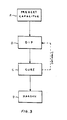
- Fig. 3 summarizes the steps in applying conformal protective coating 23 to capacitor 1 which are described above with respect to Fig. 2.
- step A the capacitor is heated to a temperature at or above the flow point of the powdered protective material 27.
- step B the heated capacitor is dipped into the powdered protective material 27.
- step C the coated capacitor may be cured (step C) and then allowed to harden (step D) or, optionally, may be dipped a second time (step B), then cured and allowed to harden (steps C and D).
- the heating, dipping and curing steps are performed sequentially by automatic machinery (not shown) which controls the movement of capacitor 1 past the radiant heaters and the immersion and removal of capacitor 1 into and from the fluidized bed apparatus 29.
- the powdered protective material 27 which is used to produce conformal protective coating 23 is an epoxy resin, such as EPC 81 epoxy powder, manufactured by the Morton-Thiokol C o.
- This epoxy resin is representative of the types of materials which can be used to produce the conformal protective coating 23. Epoxy was chosen because of its relatively high dielectric strength and its electrical insulating properties and because it is relatively impervious to chemical attack. Epoxy is also nonreactive with the aluminum alloy materials that capacitor housing 3 are usually formed from.
- a primary advantage of the above-described method is that only a single coating step is required to completely protect the exterior of capacitor 1, including both the housing and header areas. This is in contrast to prior art techniques in which an epoxy protective coating is applied only to the exterior surface of the header and, subsequently, a protective PVC sleeve is shrink-fitted over the cylindrical surface of the housing. In addition to requiring extra steps, such prior art protective coating techniques do not provide a complete and continuous seal over the entire exterior surface of the capacitor. In particular, the PVC sleeve and the prior art epoxy coating applied over the header at the open end of the capacitor do not provide a continuous seal at the header end.
- Ten capacitors having one-half inch diameter housings formed from an aluminum alloy (2 S type aluminum) were manufactured utilizing a pair of aluminum foil plates interleaved between four layers of porous paper and wound to form a series of two concentric capacitor electrodes. A pair of terminals were applied to the plates and the capacitor electrodes were disposed within the aluminum housing. A dimethylformamide solvent-based electrolyte was introduced into the housing to impregnate the capacitor electrodes. A header formed from butyl rubber was press-fitted into the open of the housing. The header included two openings for receiving the terminals from the capacitor electrodes. The header was then secured to the housing by crimping a narrow groove into the exterior of the housing adjacent the header. The capacitors were manufactured to each have a nominal capacitance of 270 ⁇ F and rated for 25 VDC.
- the capacitor was then dipped into a fluidized bed of the coating material comprised of a powdered epoxy resin manufactured by Morton-Thiokol, and sold under its tradename EPC81.
- the epoxy resin powder was kept approximately at room temperature.
- the capacitor After immersion in the powdered epoxy resin for approximately two seconds, the capacitor was removed from the epoxy resin and radiant heat was again applied for ten seconds to bring the exterior surface temperature of the capacitor back up to or slightly above the flow point of the epoxy resin. The capacitor was then reimmersed into the fluidized bed of epoxy resin powder for approximately two seconds to coat it a second time. The capacitor was then removed from the epoxy resin powder, reheated to the flowpoint temperature of the epoxy material for approximately ten seconds, and then set aside to harden.
- Example 2 Ten capacitors were constructed as described in Example 1, but rather than being coated with epoxy, a conventional polyvinyl chloride sleeve was shrink-fitted over their exterior and an epoxy coating, formed from a one-part epoxy manufactured by Mavidon Enterprises, under its tradename Uniset 906-46, was applied to the header area only of the capacitor.
- the capacitance, DC leakage and equivalent series resistance (ESR) of the two groups of capacitors from Examples 1 and 2 were initially measured.
- the capacitors were then immersed for four hours in Freon $ (Dupont type TMC) solvent to test each capacitor's ability to withstand solvent attack, then a life test was run by applying 25 VDC to the capacitors for 250 hours at 105°C.
- the capacitance, DC leakage, and ESR of each group of capacitors were subsequently measured.
- Table 1 sets forth below a comparison of the capacitance, DC leakage and ESR of the two groups of capacitors before and after the life test.
- a second group of ten capacitors were prepared in accordance with Example 1 , above, and compared with a group of ten capacitors prepared in accordance with Example 2, above, and tested for dielectric strength (breakdown voltage) under an applied AC voltage. Table 2 sets forth the results of this test.
- a third group of ten capacitors were prepared in accordance with Example 1, above, and compared with a group of ten capacitors prepared in accordance with Example 2, above, and tested for dielectric strength (breakdown voltage) under an applied DC voltage. Table 3 sets forth the results of this test.
- capacitors formed in accordance with the method of the present invention show superior resistance to contamination, stability in electrical characteristics, and improved dielectric strength over capacitors having only epoxy seals formed over their headers and PVC sleeves shrink-fitted over the cylindrical surface of the capacitor housing.
Landscapes
- Engineering & Computer Science (AREA)
- Power Engineering (AREA)
- Microelectronics & Electronic Packaging (AREA)
- Fixed Capacitors And Capacitor Manufacturing Machines (AREA)
- Cable Accessories (AREA)
Applications Claiming Priority (2)
| Application Number | Priority Date | Filing Date | Title |
|---|---|---|---|
| US68550484A | 1984-12-24 | 1984-12-24 | |
| US685504 | 1984-12-24 |
Publications (2)
| Publication Number | Publication Date |
|---|---|
| EP0187595A2 true EP0187595A2 (de) | 1986-07-16 |
| EP0187595A3 EP0187595A3 (de) | 1987-09-30 |
Family
ID=24752481
Family Applications (1)
| Application Number | Title | Priority Date | Filing Date |
|---|---|---|---|
| EP85402543A Withdrawn EP0187595A3 (de) | 1984-12-24 | 1985-12-18 | Schutzüberzug für elektrolytischen Kondensator |
Country Status (2)
| Country | Link |
|---|---|
| EP (1) | EP0187595A3 (de) |
| JP (1) | JPS61210614A (de) |
Cited By (1)
| Publication number | Priority date | Publication date | Assignee | Title |
|---|---|---|---|---|
| WO2011089009A1 (en) | 2010-01-22 | 2011-07-28 | Europlasma Nv | Method for the application of a conformal nanocoating by means of a low pressure plasma process |
Family Cites Families (5)
| Publication number | Priority date | Publication date | Assignee | Title |
|---|---|---|---|---|
| US1883932A (en) * | 1926-08-28 | 1932-10-25 | Bosch Robert | Electric condenser |
| GB444542A (en) * | 1934-10-01 | 1936-03-23 | Dubilier Condenser Co 1925 Ltd | Improvements in or relating to electrolytic condensers |
| NL6400490A (de) * | 1964-01-23 | 1965-07-26 | ||
| US3778683A (en) * | 1972-08-28 | 1973-12-11 | Gen Electric | Self-bonding capacitor case insulation |
| GB2136315B (en) * | 1983-02-04 | 1986-06-11 | Standard Telephones Cables Ltd | Insulating coatings |
-
1985
- 1985-12-18 EP EP85402543A patent/EP0187595A3/de not_active Withdrawn
- 1985-12-23 JP JP29031385A patent/JPS61210614A/ja active Pending
Cited By (1)
| Publication number | Priority date | Publication date | Assignee | Title |
|---|---|---|---|---|
| WO2011089009A1 (en) | 2010-01-22 | 2011-07-28 | Europlasma Nv | Method for the application of a conformal nanocoating by means of a low pressure plasma process |
Also Published As
| Publication number | Publication date |
|---|---|
| JPS61210614A (ja) | 1986-09-18 |
| EP0187595A3 (de) | 1987-09-30 |
Similar Documents
| Publication | Publication Date | Title |
|---|---|---|
| US5707407A (en) | Method of forming chip-formed solid electrolytic capacitor without an anode lead projecting from anode member | |
| US5140502A (en) | Solid electrolytic capacitors and method for manufacturing the same | |
| EP3828906B1 (de) | Elektrolytischer kondensator | |
| KR100199321B1 (ko) | 유기 반도체 고체 전해 콘덴서 및 그 제조 방법 | |
| KR20010088355A (ko) | 고체전해콘덴서 | |
| US3778683A (en) | Self-bonding capacitor case insulation | |
| US3058040A (en) | Electronic condensers | |
| EP0078001B1 (de) | Elektrolytkondensator und Verfahren zu seiner Herstellung | |
| JP2615712B2 (ja) | 固体電解コンデンサの製造法 | |
| JP3550232B2 (ja) | 電解コンデンサ用タブ端子の製造方法 | |
| JP4066473B2 (ja) | 固体電解コンデンサとその製造方法 | |
| JPS61210614A (ja) | 電解電気容量器用の保護被覆 | |
| US3735480A (en) | Polytetrafluoroethylene end plug seal for electrolytic capacitors | |
| CA1078935A (en) | Electrical device containing a silicone resin | |
| JPH03228305A (ja) | アルミニウム固体電解コンデンサの製造方法 | |
| KR970006432B1 (ko) | 고체 전해 콘덴서 | |
| JPS60132316A (ja) | コンデンサ | |
| JPH10163076A (ja) | 固体電解コンデンサ | |
| US3828423A (en) | Self-bonding capacitor case insulation | |
| JPS6041725Y2 (ja) | チツプ状アルミニウム電解コンデンサ | |
| KR880001650B1 (ko) | 전해콘덴서 및 그 제법 | |
| JP2869131B2 (ja) | 固体電解コンデンサ | |
| JPH097901A (ja) | 固体電解コンデンサ及びその製造方法 | |
| JP2004514268A (ja) | コンデンサ及びその製造方法 | |
| JP2771767B2 (ja) | 固体電解コンデンサの製造方法 |
Legal Events
| Date | Code | Title | Description |
|---|---|---|---|
| PUAI | Public reference made under article 153(3) epc to a published international application that has entered the european phase |
Free format text: ORIGINAL CODE: 0009012 |
|
| AK | Designated contracting states |
Kind code of ref document: A2 Designated state(s): CH DE FR GB LI NL SE |
|
| PUAL | Search report despatched |
Free format text: ORIGINAL CODE: 0009013 |
|
| AK | Designated contracting states |
Kind code of ref document: A3 Designated state(s): CH DE FR GB LI NL SE |
|
| STAA | Information on the status of an ep patent application or granted ep patent |
Free format text: STATUS: THE APPLICATION IS DEEMED TO BE WITHDRAWN |
|
| 18D | Application deemed to be withdrawn |
Effective date: 19880331 |
|
| RIN1 | Information on inventor provided before grant (corrected) |
Inventor name: LOOPER, RICK |