EP0187608A2 - Schnellverbindung für unter Druck stehende Flüssigkeitssysteme in denen der Druck 150 bar erreichen kann - Google Patents
Schnellverbindung für unter Druck stehende Flüssigkeitssysteme in denen der Druck 150 bar erreichen kann Download PDFInfo
- Publication number
- EP0187608A2 EP0187608A2 EP85440076A EP85440076A EP0187608A2 EP 0187608 A2 EP0187608 A2 EP 0187608A2 EP 85440076 A EP85440076 A EP 85440076A EP 85440076 A EP85440076 A EP 85440076A EP 0187608 A2 EP0187608 A2 EP 0187608A2
- Authority
- EP
- European Patent Office
- Prior art keywords
- bore
- pipe
- quick coupling
- diameter
- coupling according
- Prior art date
- Legal status (The legal status is an assumption and is not a legal conclusion. Google has not performed a legal analysis and makes no representation as to the accuracy of the status listed.)
- Granted
Links
Images


Classifications
-
- F—MECHANICAL ENGINEERING; LIGHTING; HEATING; WEAPONS; BLASTING
- F16—ENGINEERING ELEMENTS AND UNITS; GENERAL MEASURES FOR PRODUCING AND MAINTAINING EFFECTIVE FUNCTIONING OF MACHINES OR INSTALLATIONS; THERMAL INSULATION IN GENERAL
- F16L—PIPES; JOINTS OR FITTINGS FOR PIPES; SUPPORTS FOR PIPES, CABLES OR PROTECTIVE TUBING; MEANS FOR THERMAL INSULATION IN GENERAL
- F16L37/00—Couplings of the quick-acting type
- F16L37/08—Couplings of the quick-acting type in which the connection between abutting or axially overlapping ends is maintained by locking members
- F16L37/084—Couplings of the quick-acting type in which the connection between abutting or axially overlapping ends is maintained by locking members combined with automatic locking
- F16L37/091—Couplings of the quick-acting type in which the connection between abutting or axially overlapping ends is maintained by locking members combined with automatic locking by means of a ring provided with teeth or fingers
Definitions
- the invention relates to a quick connector for pressurized fluid circuits whose pressure can reach one hundred and fifty bars, composed of a body having a bore in which the end of the pipe of the circuit is engaged, and comprising a retaining washer, a dilator ring, a seal and an upper retaining ring.
- connection is provided at its ends with retaining rings glued or welded to the cylindrical body.
- retaining rings glued or welded to the cylindrical body.
- the pressure in the different circuits used is very variable.
- the pressure is three bars in the water cooling circuit and in the oil or diesel circuit, ten bars in the oil cooling circuit, ten to twenty bars in the braking circuit and d compressed air for heavy goods vehicles, 30 bars in the air conditioning circuit and around 100 bars in the power steering circuit. It is therefore necessary to have at its disposal a large range of quick couplings suitable for different circuits, which the coupling described in the aforementioned US patent does not allow.
- this connection comprises a reinforcing bush cored in the mass, which, on the one hand, poses a machining problem because it is necessary to reduce the speed of the machines by about 50% and, on the other hand, makes it very difficult to produce this socket in harder materials, such as steel or aluminum alloys.
- the present invention aims to remedy these drawbacks.
- the invention as characterized in the claims solves the problem of creating a quick connector for pressurized fluid circuits, the pressure of which can reach one hundred and fifty bars, composed of a body having a bore in which is engaged the end of the circuit pipe, and comprising a retaining washer, an expansion ring, a seal, a reinforcing bush that can be added and an upper retaining ring, this upper retaining ring, housed in a first recess arranged in the bore of the body of the fitting and ending in a shoulder, said upper retaining ring cooperating with the seal, the dilator ring, the retaining washer and the reinforcing sleeve for positioning and anchoring the end of the pipe and comprising a recess whose shoulder serves as a stop for crimping the body.
- the advantages obtained by the present invention essentially consist in that this quick coupling, mounted on pressurized fluid circuits, makes it possible to reach pressures of one hundred and fifty bars and can be used for polyamide pipes, monotube type or bi-tube, in aluminum, copper and steel, without the ends of these pipes or tubes being prepared by prereading or pre-machining, and without the upper retaining ring being glued or welded to the body.
- the machining times of the fitting bodies are considerably accelerated and there is the possibility of using more noble materials such as steel, stainless steel, l aluminum or others.
- the invention makes it possible to limit the stocks of finished products, identical machining for a given connector body which can be used for example, for pipes having an identical outside diameter but a different inside diameter, by simply changing the sleeve reported. It is certain that it is less expensive to interchange fitted sockets than to produce different bodies according to the internal diameter of the pipe.
- the quick connector 1 comprises a body 2 having a bore 3 in which are arranged anchoring means 4 and dilator means 5 cooperating with sealing means 6, the whole being held by an upper retaining ring 7.
- this bore 3 is engaged the end 8 of a pipe 9 of a circuit of a pressurized fluid.
- This pipe 9 can be made of polyamide, aluminum, copper, or even steel.
- the body 2 has at one of its ends 10 a threaded end piece 11. To screw the latter into a threaded hole of a female connector not shown, said body 2 is provided with a hexagon 12.
- a first recess 13 is produced located near the end 14, into which the end 8 of the pipe 9 is introduced and the shoulder 15 of which serves as a stop for the upper retaining ring 7.
- This first step 13 is followed by a second step 16 serving as a housing for the sealing means 6, the dilator means 5 and the anchoring means 4, the latter bearing against the shoulder 17.
- the bottom 18 of this second recess 16 comprises centering means formed by a frustoconical recess 19 followed by a blind bore 20.
- the purpose of this frustoconical recess 19 is to direct the end 8 of the pipe 9 into the blind bore 20 and , therefore, center said end 8 of pipe 9 in body 2.
- the body 2 Concentrically to the bore 3, the body 2 comprises a reinforcing bush 21 whose front end 22 is slightly set back relative to the end 14 of said body 2.
- this reinforcing sleeve 21 and the body 2 are in one piece.
- the end 8 of the pipe 9 is threaded onto the reinforcement sleeve 21 and the internal wall 23 follows the outer periphery 24 of the reinforcement sleeve 21 while the external wall 25 follows the internal wall 26 of the blind bore 20 (see also figure 2).
- the end 8 of the pipe 9 is held in place by the anchoring means 4.
- the upper retaining ring 7 cooperates with the various sealing means 6, expansion 5, anchoring 4 and with the bushing. reinforcement 21 to allow positioning and anchoring of the end 8 of the pipe 9.
- These anchoring means 4 are constituted by a retaining washer 27 formed of an outer ring 28 conforming to the second step 16, the edge 29 of this outer ring 28 bearing against the shoulder 17.
- This outer ring 28 comprises a plurality of strips 30, 31, 32 arranged in a fan shape with respect to the center 33 of the retaining washer 27. These strips 30, 31, 32 form an angle with the outer ring 28 and are directed towards the shoulder 17.
- the internal diameter 34 of the retaining washer 27 is slightly less than the diameter 35 of the end 8 of the pipe 9.
- Each strip 31 is independent of the neighboring strips 30, 32 and therefore is elastic with respect to its connection edge 36 with the outer ring 28.
- this retaining washer 27 is made of stainless steel with a hardness greater than that of the pipe 9 even if the latter is made of steel to be certain that the strips 30, 31, 32 become embedded in the flesh of the pipe 9.
- the strips 30, 31, 32 cannot, during the introduction of the tube 9, scratch the latter in its sealing zone.
- the dilator means 5 are a dilator ring 37.
- This comprises, on the side of the retaining washer 27, a stop formed by a frustoconical surface 38 whose small base is located on the side of the retaining washer 27 against which bear the lamellae 30, 3 1, 32 of the retaining washer 27 to prevent said leaves 30, 31, 32, when the effect of dislocation, turn around completely, which would nullify their effect anchor.
- This frustoconical surface 38 terminates in a centering groove 39 in which the front edge 40 of the retaining washer 27 is housed.
- the expansion ring 37 On the side of the sealing means 6, the expansion ring 37 has a wedge-shaped edge 43.
- the cylindrical bore 41 leads to a frustoconical bore 42 which widens in the direction of the wedge-shaped edge 43 directed towards the sealing means 6.
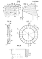
- This wedge-shaped edge 43 is connected by a rounded 44 to a frustoconical external surface 45 connecting said edge 43 to the outer periphery 46 of the dilator ring 37. Due to the particular shape of the wedge-shaped edge 43 as visible in FIG. 5, this edge 43 has the shape of a corner, and causes the axial expansion of the sealing means 6.
- the sealing means 6 are a seal 47 having on its face 48 directed towards the dilator ring 37 two circular lips 49, 50, one inside 49, matching the outside wall 25 of the end 8 of the pipe 9 while the 'other exterior 50, bears against the second recess 16 of the bore 3 of the body 2.
- These two circular lips 49, 50 form a certain angle 51 between them and in this angle 51 is placed the edge 43 of the ring dilator 37 causing the separation of said circular lips 49, 50.
- a semi-round groove 53 is produced in its outer face 52, which makes it possible to obtain two contact rings 54, 55.
- the upper retaining ring 7 has a recess 62, the shoulder 63 of which serves as a stop for crimping 64 holding the various elements 4, 5, 6 and 7.
- This crimping 64 is simple to perform and provides a high resistance to pressure and optimal contact between the different elements 4, 5, 6, 7, the end 8 of the pipe 9 and the reinforcing sleeve 21.
- the upper retaining ring 7 has a thread allowing said ring 7 to be screwed into a thread produced in the first recess 13 of the bore 3 of the body 2.
- the quick connector 1 can be executed in the form of a straight connector but also of stamped parts such as elbows, tee and others. It can make it possible to connect a pipe to a member but also two pipes to one another when is made in double junction. In all cases, it plays the role of anti-kinking when mounting flexible elements.
- This embodiment of the quick coupling has the advantage of having excellent resistance to high pressures, for example one hundred and fifty bars.
- the quick coupling 101 comprises a body 102 in which a bore 103 is produced intended to receive the end 108 of a pipe 109 of the pressurized fluid circuit. This end 108 enters the body 102 from the end 114 of the latter. At the other end 110, the body 102 has an orifice 165 whose diameter is less than the diameter of the bore 103, which makes it possible to obtain a shoulder 166. Against this shoulder 166 abuts the end 167 of a inner sleeve reported 168.
- the bore 103 has a recess 116 making it possible to obtain a shoulder 117.
- anchoring means 104 consisting of a retaining washer formed by an outer ring 128 and a plurality of elastic strips 130 These elastic strips 130 have a certain inclination directed towards the shoulder 117 and, after assembly, become encrusted in the end 108 of the pipe 109 made of polyamide, aluminum, copper or steel.
- dilators 105 are applied, cooperating with sealing means 106.
- the bore 103 has another recess 113, the shoulder 115 of which serves as a stop for an outer retaining ring 107.
- the latter comprises a recess 162 cooperating with a crimp 164 to hold in the bore 103 the inner insert bushing 168, the anchoring means 104, the dilator means 105, the sealing means 106 and the upper retaining ring 107.
- the inner insert sleeve 168 made of steel, stainless steel, aluminum or other hard material, consists of a cylindrical end piece 169 and a cylindrical seat 170.
- the cylindrical end piece 169 is threaded the end 108 of the pipe 109 To this end, this cylindrical end piece 169 has at its free end 171 a chamfer 172 facilitating the centering of the end 108 of the pipe 109 relative to the cylindrical end-piece 169.
- the external diameter 173 of the latter corresponds to the internal diameter of the pipe 109.
- the cylindrical seat 170 has an outer diameter 174 slightly smaller than the diameter of the bore 103 of the body 102 for a press fit of the inner sleeve reported 168 in said bore 103.
- end 167 has a chamfer 175.
- the same body 102 can be used for different pipe diameters.
- the outside diameter 173 of the cylindrical end piece 169 can vary as a function of the diameter of the pipe 108 while the outside diameter 174 of the cylindrical seat 170 is constant and corresponds to the bore 103 of the body 102.
- a groove 178 is made in the face 177 of the cylindrical seat 170.
- the internal wall 179 is situated in the extension of the cylindrical end piece 169 while the diameter of the external wall 180 corresponds to the external diameter of the pipe 109 To facilitate the introduction of the end 108 of the pipe 109, this external wall 180 comprises a chamfered end 181.
Landscapes
- Engineering & Computer Science (AREA)
- General Engineering & Computer Science (AREA)
- Mechanical Engineering (AREA)
- Quick-Acting Or Multi-Walled Pipe Joints (AREA)
Priority Applications (1)
| Application Number | Priority Date | Filing Date | Title |
|---|---|---|---|
| AT85440076T ATE52320T1 (de) | 1985-01-03 | 1985-12-20 | Schnellverbindung fuer unter druck stehende fluessigkeitssysteme in denen der druck 150 bar erreichen kann. |
Applications Claiming Priority (4)
| Application Number | Priority Date | Filing Date | Title |
|---|---|---|---|
| FR8500113A FR2578306B1 (fr) | 1985-01-03 | 1985-01-03 | Raccord rapide pour circuits de fluide sous pression |
| FR8500113 | 1985-01-03 | ||
| FR8508375 | 1985-05-31 | ||
| FR8508375A FR2582771B2 (fr) | 1985-05-31 | 1985-05-31 | Raccord rapide pour circuits de fluide sous pression |
Publications (3)
| Publication Number | Publication Date |
|---|---|
| EP0187608A2 true EP0187608A2 (de) | 1986-07-16 |
| EP0187608A3 EP0187608A3 (en) | 1987-05-13 |
| EP0187608B1 EP0187608B1 (de) | 1990-04-25 |
Family
ID=26224318
Family Applications (1)
| Application Number | Title | Priority Date | Filing Date |
|---|---|---|---|
| EP19850440076 Expired - Lifetime EP0187608B1 (de) | 1985-01-03 | 1985-12-20 | Schnellverbindung für unter Druck stehende Flüssigkeitssysteme in denen der Druck 150 bar erreichen kann |
Country Status (2)
| Country | Link |
|---|---|
| EP (1) | EP0187608B1 (de) |
| DE (1) | DE3577344D1 (de) |
Cited By (5)
| Publication number | Priority date | Publication date | Assignee | Title |
|---|---|---|---|---|
| WO1999004192A1 (en) * | 1997-07-16 | 1999-01-28 | Ranco Of Delaware, Inc. | Method of attaching supply conduit to a solenoid operated valve |
| CN103697271A (zh) * | 2013-12-03 | 2014-04-02 | 山东祺龙海洋石油钢管股份有限公司 | 四头螺纹导管快速连接装置 |
| CN104594822A (zh) * | 2014-09-30 | 2015-05-06 | 山东祺龙海洋石油钢管股份有限公司 | 四头螺纹隔水套管快速连接装置 |
| CN104806835A (zh) * | 2015-04-24 | 2015-07-29 | 佛山市日丰企业有限公司 | 一种铝塑复合管用直插式接头 |
| US11988305B2 (en) | 2019-12-19 | 2024-05-21 | Oetiker Ny, Inc. | Fluid connector including internal retaining clip |
Families Citing this family (1)
| Publication number | Priority date | Publication date | Assignee | Title |
|---|---|---|---|---|
| DE20003983U1 (de) * | 2000-03-02 | 2001-07-19 | WIRA Fahrzeug- und Maschinenteile GmbH, 51688 Wipperfürth | Rohranschlußverbindung |
Family Cites Families (5)
| Publication number | Priority date | Publication date | Assignee | Title |
|---|---|---|---|---|
| GB1486671A (en) * | 1975-01-25 | 1977-09-21 | Hepworth Plastics Ltd | Pipe couplings |
| US4146254A (en) * | 1976-03-31 | 1979-03-27 | Bristol Products, Inc. | Coupler for tubing |
| GB2051280B (en) * | 1979-06-20 | 1983-06-22 | Guest Southern Ltd John | Coupling for tubes |
| GB2070176A (en) * | 1980-02-22 | 1981-09-03 | B & C Water Fittings Ltd | Pipe coupling |
| IT1168408B (it) * | 1981-07-24 | 1987-05-20 | Metal Work Spa | Sistema di collegamento dei raccordi automatici per tubazioni ai dispositivi per l'erogazione,il controllo e l'utilizzo fluidi liquidi o gassosi |
-
1985
- 1985-12-20 DE DE8585440076T patent/DE3577344D1/de not_active Expired - Lifetime
- 1985-12-20 EP EP19850440076 patent/EP0187608B1/de not_active Expired - Lifetime
Cited By (5)
| Publication number | Priority date | Publication date | Assignee | Title |
|---|---|---|---|---|
| WO1999004192A1 (en) * | 1997-07-16 | 1999-01-28 | Ranco Of Delaware, Inc. | Method of attaching supply conduit to a solenoid operated valve |
| CN103697271A (zh) * | 2013-12-03 | 2014-04-02 | 山东祺龙海洋石油钢管股份有限公司 | 四头螺纹导管快速连接装置 |
| CN104594822A (zh) * | 2014-09-30 | 2015-05-06 | 山东祺龙海洋石油钢管股份有限公司 | 四头螺纹隔水套管快速连接装置 |
| CN104806835A (zh) * | 2015-04-24 | 2015-07-29 | 佛山市日丰企业有限公司 | 一种铝塑复合管用直插式接头 |
| US11988305B2 (en) | 2019-12-19 | 2024-05-21 | Oetiker Ny, Inc. | Fluid connector including internal retaining clip |
Also Published As
| Publication number | Publication date |
|---|---|
| DE3577344D1 (de) | 1990-05-31 |
| EP0187608A3 (en) | 1987-05-13 |
| EP0187608B1 (de) | 1990-04-25 |
Similar Documents
| Publication | Publication Date | Title |
|---|---|---|
| EP0893641B1 (de) | Vorrichtung zum Verbinden von zwei Rohrstücken und Anwendung der Verbindung von Rohrstücken | |
| EP0244044B1 (de) | Akustisches Filter | |
| CA2495883C (fr) | Joint filete tubulaire etanche vis-a-vis du milieu exterieur | |
| FR2493460A1 (fr) | Joint annulaire d'etancheite et de raclage a arret automatique pour verin pneumatique | |
| EP0187608B1 (de) | Schnellverbindung für unter Druck stehende Flüssigkeitssysteme in denen der Druck 150 bar erreichen kann | |
| FR2576658A1 (fr) | Structure d'etancheite | |
| EP2162663A2 (de) | Steckverbinder mit verbesserter aussenreinigung | |
| EP1977152B1 (de) | Rohrförmige verbindung | |
| FR2758379A1 (fr) | Cartouche d'implantation pour un raccord d'un tuyau destine a prendre place dans un logement | |
| FR2502736A1 (fr) | Dispositif de raccordement d'un conduit de piquage sur un conduit principal | |
| EP0581678B1 (de) | Schlauch mit radialer Spannvorrichtung zum Verbinden mit einem Rohrende; Schlauchverbindung mit diesem Schlauch | |
| FR2866094A1 (fr) | Raccord mecanique destine a assurer la solidarisation d'un tuyau en matiere plastique a un appareil de robinetterie | |
| FR2511114A1 (fr) | Systeme de vissage assurant une liaison etanche entre tubes | |
| FR2582771A2 (fr) | Raccord rapide pour circuits de fluide sous pression | |
| EP0336866A1 (de) | Trennbare Rohrkupplung | |
| FR2578306A1 (fr) | Raccord rapide pour circuits de fluide sous pression | |
| FR2683887A1 (fr) | Raccord pour tubes resistant a la pression. | |
| EP1619437A1 (de) | Verbindung einer Abzweigung | |
| FR2888307A1 (fr) | Raccord pour robinetterie. | |
| FR2558524A1 (fr) | Pic de taille pour mineraux et ensemble comportant ce pic | |
| FR2665510A1 (fr) | Procede de raccordement etanche et raccord etanche correspondant. | |
| FR2634533A1 (fr) | Bague d'etancheite | |
| FR2499667A1 (fr) | Raccord, notamment pour vannes et robinets | |
| EP0046705A1 (de) | Verbindung zwischen einer Kunststoffleitung und einer metallischen Leitung für eine Flüssigkeit unter Druck | |
| EP1431644B1 (de) | Dichte Verbindung zwischen einem Schlauch und einem Körper |
Legal Events
| Date | Code | Title | Description |
|---|---|---|---|
| PUAI | Public reference made under article 153(3) epc to a published international application that has entered the european phase |
Free format text: ORIGINAL CODE: 0009012 |
|
| AK | Designated contracting states |
Kind code of ref document: A2 Designated state(s): AT BE CH DE GB IT LI LU NL SE |
|
| PUAL | Search report despatched |
Free format text: ORIGINAL CODE: 0009013 |
|
| AK | Designated contracting states |
Kind code of ref document: A3 Designated state(s): AT BE CH DE GB IT LI LU NL SE |
|
| 17P | Request for examination filed |
Effective date: 19870808 |
|
| 17Q | First examination report despatched |
Effective date: 19880824 |
|
| GRAA | (expected) grant |
Free format text: ORIGINAL CODE: 0009210 |
|
| AK | Designated contracting states |
Kind code of ref document: B1 Designated state(s): AT BE CH DE GB IT LI LU NL SE |
|
| REF | Corresponds to: |
Ref document number: 52320 Country of ref document: AT Date of ref document: 19900515 Kind code of ref document: T |
|
| REF | Corresponds to: |
Ref document number: 3577344 Country of ref document: DE Date of ref document: 19900531 |
|
| ITF | It: translation for a ep patent filed | ||
| GBT | Gb: translation of ep patent filed (gb section 77(6)(a)/1977) | ||
| ITTA | It: last paid annual fee | ||
| PLBE | No opposition filed within time limit |
Free format text: ORIGINAL CODE: 0009261 |
|
| STAA | Information on the status of an ep patent application or granted ep patent |
Free format text: STATUS: NO OPPOSITION FILED WITHIN TIME LIMIT |
|
| 26N | No opposition filed | ||
| PGFP | Annual fee paid to national office [announced via postgrant information from national office to epo] |
Ref country code: CH Payment date: 19921223 Year of fee payment: 8 |
|
| PGFP | Annual fee paid to national office [announced via postgrant information from national office to epo] |
Ref country code: NL Payment date: 19921231 Year of fee payment: 8 |
|
| PGFP | Annual fee paid to national office [announced via postgrant information from national office to epo] |
Ref country code: LU Payment date: 19930105 Year of fee payment: 8 |
|
| PGFP | Annual fee paid to national office [announced via postgrant information from national office to epo] |
Ref country code: BE Payment date: 19930127 Year of fee payment: 8 |
|
| EPTA | Lu: last paid annual fee | ||
| PG25 | Lapsed in a contracting state [announced via postgrant information from national office to epo] |
Ref country code: LU Free format text: LAPSE BECAUSE OF NON-PAYMENT OF DUE FEES Effective date: 19931220 |
|
| PG25 | Lapsed in a contracting state [announced via postgrant information from national office to epo] |
Ref country code: LI Effective date: 19931231 Ref country code: CH Effective date: 19931231 Ref country code: BE Effective date: 19931231 |
|
| BERE | Be: lapsed |
Owner name: SOC. DES RACCORDS ANOFLEX SODERAX Effective date: 19931231 Owner name: SOC. DES FLEXIBLES ANOFLEX Effective date: 19931231 |
|
| PG25 | Lapsed in a contracting state [announced via postgrant information from national office to epo] |
Ref country code: NL Effective date: 19940701 |
|
| NLV4 | Nl: lapsed or anulled due to non-payment of the annual fee | ||
| REG | Reference to a national code |
Ref country code: CH Ref legal event code: PL |
|
| EAL | Se: european patent in force in sweden |
Ref document number: 85440076.9 |
|
| PGFP | Annual fee paid to national office [announced via postgrant information from national office to epo] |
Ref country code: GB Payment date: 19951211 Year of fee payment: 11 |
|
| PGFP | Annual fee paid to national office [announced via postgrant information from national office to epo] |
Ref country code: AT Payment date: 19951213 Year of fee payment: 11 |
|
| PGFP | Annual fee paid to national office [announced via postgrant information from national office to epo] |
Ref country code: SE Payment date: 19951215 Year of fee payment: 11 |
|
| PGFP | Annual fee paid to national office [announced via postgrant information from national office to epo] |
Ref country code: DE Payment date: 19951222 Year of fee payment: 11 |
|
| PG25 | Lapsed in a contracting state [announced via postgrant information from national office to epo] |
Ref country code: GB Effective date: 19961220 Ref country code: AT Effective date: 19961220 |
|
| PG25 | Lapsed in a contracting state [announced via postgrant information from national office to epo] |
Ref country code: SE Effective date: 19961221 |
|
| GBPC | Gb: european patent ceased through non-payment of renewal fee |
Effective date: 19961220 |
|
| PG25 | Lapsed in a contracting state [announced via postgrant information from national office to epo] |
Ref country code: DE Effective date: 19970902 |
|
| EUG | Se: european patent has lapsed |
Ref document number: 85440076.9 |