EP0187625B1 - Automatische Maschine zum kontinuierlichen Verpacken von Gegenständen - Google Patents
Automatische Maschine zum kontinuierlichen Verpacken von Gegenständen Download PDFInfo
- Publication number
- EP0187625B1 EP0187625B1 EP19850830314 EP85830314A EP0187625B1 EP 0187625 B1 EP0187625 B1 EP 0187625B1 EP 19850830314 EP19850830314 EP 19850830314 EP 85830314 A EP85830314 A EP 85830314A EP 0187625 B1 EP0187625 B1 EP 0187625B1
- Authority
- EP
- European Patent Office
- Prior art keywords
- articles
- wired
- movable
- microprocessor
- height
- Prior art date
- Legal status (The legal status is an assumption and is not a legal conclusion. Google has not performed a legal analysis and makes no representation as to the accuracy of the status listed.)
- Expired
Links
- 238000012856 packing Methods 0.000 title claims description 7
- 230000006872 improvement Effects 0.000 title description 11
- 238000003780 insertion Methods 0.000 claims description 19
- 230000037431 insertion Effects 0.000 claims description 19
- 230000009471 action Effects 0.000 claims description 5
- 238000011144 upstream manufacturing Methods 0.000 claims description 5
- 238000001514 detection method Methods 0.000 claims description 4
- 238000006073 displacement reaction Methods 0.000 claims description 4
- 210000001364 upper extremity Anatomy 0.000 claims 1
- 230000000875 corresponding effect Effects 0.000 description 4
- 230000008901 benefit Effects 0.000 description 3
- 230000007246 mechanism Effects 0.000 description 3
- 238000000034 method Methods 0.000 description 3
- 230000002596 correlated effect Effects 0.000 description 2
- 230000007423 decrease Effects 0.000 description 2
- 238000012423 maintenance Methods 0.000 description 2
- 230000008569 process Effects 0.000 description 2
- 230000008859 change Effects 0.000 description 1
- 239000002537 cosmetic Substances 0.000 description 1
- 229940079593 drug Drugs 0.000 description 1
- 239000003814 drug Substances 0.000 description 1
- 230000001939 inductive effect Effects 0.000 description 1
- 230000002452 interceptive effect Effects 0.000 description 1
- 238000004519 manufacturing process Methods 0.000 description 1
- 238000012546 transfer Methods 0.000 description 1
- 238000013519 translation Methods 0.000 description 1
Images

Classifications
-
- B—PERFORMING OPERATIONS; TRANSPORTING
- B65—CONVEYING; PACKING; STORING; HANDLING THIN OR FILAMENTARY MATERIAL
- B65B—MACHINES, APPARATUS OR DEVICES FOR, OR METHODS OF, PACKAGING ARTICLES OR MATERIALS; UNPACKING
- B65B35/00—Supplying, feeding, arranging or orientating articles to be packaged
- B65B35/10—Feeding, e.g. conveying, single articles
- B65B35/20—Feeding, e.g. conveying, single articles by reciprocating or oscillatory pushers
- B65B35/205—Feeding, e.g. conveying, single articles by reciprocating or oscillatory pushers linked to endless conveyors
-
- B—PERFORMING OPERATIONS; TRANSPORTING
- B65—CONVEYING; PACKING; STORING; HANDLING THIN OR FILAMENTARY MATERIAL
- B65B—MACHINES, APPARATUS OR DEVICES FOR, OR METHODS OF, PACKAGING ARTICLES OR MATERIALS; UNPACKING
- B65B39/00—Nozzles, funnels or guides for introducing articles or materials into containers or wrappers
- B65B39/12—Nozzles, funnels or guides for introducing articles or materials into containers or wrappers movable towards or away from container or wrapper during filling or depositing
-
- B—PERFORMING OPERATIONS; TRANSPORTING
- B65—CONVEYING; PACKING; STORING; HANDLING THIN OR FILAMENTARY MATERIAL
- B65B—MACHINES, APPARATUS OR DEVICES FOR, OR METHODS OF, PACKAGING ARTICLES OR MATERIALS; UNPACKING
- B65B57/00—Automatic control, checking, warning, or safety devices
- B65B57/02—Automatic control, checking, warning, or safety devices responsive to absence, presence, abnormal feed, or misplacement of binding or wrapping material, containers, or packages
- B65B57/06—Automatic control, checking, warning, or safety devices responsive to absence, presence, abnormal feed, or misplacement of binding or wrapping material, containers, or packages and operating to control, or to stop, the feed of articles or material to be packaged
Definitions
- the invention belongs to the vast technical field concerned with automatic machines, such as, for example, machines for the continuous packing of articles (e.g. medicines or cosmetics) in containers (e.g. cases), of the kind comprising two coplanar lines, side by side, one line being for the infeeding of the articles and the other for the infeeding of the containers, in the region of a station where the articles are inserted into the containers.
- automatic machines such as, for example, machines for the continuous packing of articles (e.g. medicines or cosmetics) in containers (e.g. cases), of the kind comprising two coplanar lines, side by side, one line being for the infeeding of the articles and the other for the infeeding of the containers, in the region of a station where the articles are inserted into the containers.
- the article infeed line consists of a number of trays, integral with a pair of looped chains moving in a line perpendicular to the axis of the trays.
- the trays are designed to receive, from a magazine, (for example, of the kind defended in DE-A-3238927) a preset number of articles (for example, 1, 2, 3, etc.). This means that the device which "unlatches" the articles from the magazine has to be adjusted (by the operator on the spot) and a detector provided, between the magazine and the aforementioned station, to detect the height of the pile of products in each tray.
- the detector is mounted so that it can be adjusted in height when the number of articles in each pile is varied.
- the container magazine (for example, located under the aforementioned container infeed line as described in DE-A-3103149) where the containers are housed, in flat tubular state, consists basically of two sloping bars and two angles, on the outside of the bars.
- the container infeed line comprises, amongst other things: a longitudinal track serving both to support the containers and guide the bottoms thereof; means (such as: pegs of at least two chains) for transferring the containers from the insertion station to an outfeed station; two longitudinal bars, located over the aforementioned track and serving to guide the containers moving along underneath.
- the height of the said bars above the track is adjusted by suitable means whenever it is necessary to change the size of the parallelepiped containers (or cases) obtained by "erecting" the flat tubular container blanks.
- the said devices consist of hand-operated mechanical means placed beside and/or above the conveyor: the problem with these is that they obstruct assembly, setup and maintenance operations on the lines.
- the electromechanical means just referred to consist of a variety of mechanisms of varying complexity located over the conveyor with the result that the difficulties with the traditional solution (that is, hand-operated mechanical devices) are not alleviated but accentuated.
- the object of this invention is to make available such improvements to an automatic machine for the continuous packing of articles as to centralize the control of the aforementioned hand-operated means, of the aforementioned devices and of the "setting" of the number of articles fed by the magazine to the trays on the article infeed line.
- the invention envisages suitable electromechanical means interfaceable with a microprocessor mounted on the machine itself or a microprocessor outside the machine in common with other automatic machines.
- the invention also envisages that the devices to operate the longitudinal bars be of such shape and form as not to encumber the area above the bars, which constitutes an improvement in that assembly and maintenance operations on the 5 aforementioned lines are facilitated.
- a further improvement envisaged by the invention is the provision of means to enable the operator to handle the containers at the article insertion station without negatively affecting the 10 full containers downstream that have already gone through the station.
- an automatic machine for the continuous packing of articles comprising: two lines, one for the infeed- 15 ing of the articles and the other for the infeeding of the containers, coplanar and side by side, in the region of a station where the articles are inserted into the containers; a magazine, located upstream of the article infeed line, designed to feed the 20 trays on the article infeed line with a preset number of articles; means, located in between the said magazine and the insertion station, for detecting the number of articles present in each tray, the said means being movable vertically; a 25 second magazine for housing the containers in flat tubular state and located under the container infeed line and upstream thereof; a device between the second magazine and the article infeed line designed to transform the containers 30 from flat tubular blanks into parallelepiped containers; at least two longitudinal bars, placed over the aforementioned container infeed line, for locating and guiding the containers underneath sliding on a longitudinal track under the action of 35 drive means; a device for the linear adjustment of the height of the said
- each longitudinal bar conisists of 5 two segments, one fixed and one movable, hinged to each other, the said movable segment, which is located at the insertion station, being movable vertically between two extreme points and adjustable when it is at the bottom position 10 so that its alignment in relation to the fixed segment can be adjusted.
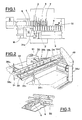
- means 1 and 2 indicate two infeed lines, the former for the infeeding of the articles to be packed 3 and the latter for the infeeding of the cases (or containers) 4.
- the two lines are coplanar and side by side in 55 the region of a station S.
- Line 1 is made up of a number of trays 5 (translating through H), adjustable in width, into each of which a magazine of known kind (and therefore named generically) discharges a preset 60 quantity (number) of the said articles 3.
- the means operating the magazine (not illustrated) must therefore be "set” for the required number of articles: the setting is controlled through a centralized microprocessor 100 ( Figure 8).
- the lines 1 and 2 run at the same speed, which is also the speed at which the push-rods 7 move, the said push-rods being movable also perpendicularly to direction H so as to push the pile of articles 3 into cases 4.
- a sensor 8 (of inductive type, for example) carried by an element 9, rotatably mounted on a slide 10 and able to rotate perpendicularly to direction H.
- the vertical translation of the slide 10 allows the setting of the height of the element 9 and sensor 8 in respect of the line 1, according to the size of the articles 3 that are passing under the sensor 8, placed inside the trays 5.
- the sensor 12 also detects the rotation of element 9.
- Sensors 8, 12, 14 and 15 and motor 13a are controlled by microprocessor 100.
- Sensor 8 detects the presence of a preset number of articles 3 in trays 5. If the number of articles in a tray is less than the preset number, sensor 8 detects the anomaly. If the number is greater than the preset number, sensor 8 intercepts the top article of the pile and gives an "O.K.” signal which is in fact wrong; this is picked up (and the signal cancelled) by sensor 12 when movable element 9 rotates as a result of the lifting of sensor 8 consequent on its having intercepted the top article.
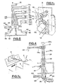
- Magazine 16 which houses containers 4 in flat tubular state, is located upstream of the line 2, under station S ( Figure 6b).
- a suitable device 17 - (such as defended in DE-A-3 103 149) "erects" the blanks to form cases (of parallel shape, for instance) and transfer them to line 2.
- the magazine 16 is carried on a stem 18, driven by a motor, 20, through electromechanical means 19 which impart vertical translational motion through F1 and F2; a limit sensor 21 detects the zero point of the stroke of stem 18, while another sensor, 22, "gauges" the fractions of revolution of the drive shaft 20.
- Motor 20 and the sensor 21 and 22 depend on microprocessor 100.
- the magazine 16 has two oblique bars 23 and two sides 24a and 24b, parallel to the brs and freely supported by a crossbar 25 ( Figure 6a).
- the aforementioned sides are moved in directions K1, K2 by electromechanical means 26 and 27 driven by motors 26a and 27a.
- Means 26 and 27 are associated to sensor pairs 28a, 28b and 29a, 29b.
- Sensors 28a and 29a define the "zero" of the slides of the associated slides 24a and 24b, while the remaining sensors 28b and 29b, "gauge” the fractions of a revolution of the drive shafts of motors 26a and 27a respectively.
- Sensors 28a and b and 29a and b, as well as motors 26a and 27a, are controlled by microprocessor 100.
- the line 2 for the infeeding of cases 4 comprises, amongst other things, a longitudinal track 30 with longitudinal grooves which pegs 31 slide in, the said pegs being fastened to chains 31 a and equally spaced to form receptacles 32 for the containers.
- Track 30 serves to support and guide the bottoms of cases 4, while the tops thereof are guided by two longitudinal bars 34 ( Figure 2).
- Bars 34 are cantilevered to four crosspieces, 35a, 35b, 35c and 35d, facing the outside of the line and moved up and down by electromechanical means 36a, b, c, d.
- 37 indicates an internally threaded sleeve guided axially by structure 38 of the machine.
- a threaded stem 39 is screwed coaxially to the said sleeve 37 in such a way as to be prevented from moving vertically but carried in rotation by electromechanical means 79 driven by motor 40 (or manually by means of a knob, 39a).
- the "zero" of the stroke of the sleeve is defined by a limit sensor 41, while another sensor, 42, . "gauges" the fractions of a revolution of the motor 40.
- sprocket 43 (splined to stem 39) and toothed belt 44 drives the electromechanical unit 36b which is the same as that described above, is linked to sensors 41 and 42 and driven by the aforementioned motor 40.
- the unit 36c is similar to units 36a and b and is provided with a motor, 65, and sensors 46 and 47 ( Figure 8).
- the electromechanical unit 36d, associated arm 35d, has a bracket 48 containing suitable means for transmitting motion, not illustrated, driven as described above by motor 65.
- the said unit is linked to sensors 46 and 47 and is driven by motor 65.
- Motors 40 and 65, as well as sensors 41, 42 and 46, 47 are controlled by microprocessor 100.
- units 36a, b, c and d are located under and to one side of line 2 and that electromechanical means 79, with associated motors 40 and 65 are located in the bottom section of structure 38.
- electromechanical means 79, with associated motors 40 and 65 are located in the bottom section of structure 38.
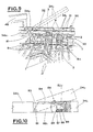
- the longitudinal bars consist each of two segments, 34a and 34b, one fixed and one movable, respectively, hinged together by means 81, the movable segment being located at the insertion station, S.
- each push rod 7, actuated in synchronism with lines 1 and 2 inserts a preset number of articles 3 into the corresponding case 4 from the open end, 4a, of the case.
- 82c indicates a portion of the aforementioned fixed segment 34a and 82d a space in movable segment 34b.
- the top 83 of the said portion 82c matches with a rest of the said space 82d.
- the movable segment has an associated block 86 with a ball 87 pushed out partially from one end by spring 88.
- segment 34b When segment 34b is in "lowered" position, the said ball goes into a socket 89 made in the aforementioned portion 82c of the fixed segment 34a.
- the lifting action exerted on the segment 34b when the insertion station S is called into operation overcomes the resistance of spring 88, thus enabling the ball 87 to come free of the socket 89.
- the operator can stop the machine associated to lines 1 and 2, and raise the movable segment 34b of the aforementioned bars 34, so as to correct the position of, or remove, the container (or containers) that is causing the jam. After doing this, the operator can move the aforementioned movable segment back to "lowered" position to start the machines up again.
- the means just referred to make it quick and easy for the operator to set things right at the insertion station S without negatively interfering with the cases already downstream of the station and waiting for subsequent operations.
- Another notable advantage is that the movable segment 34b is adjustably mounted to be aligned with the fixed segment 34a. This makes it possible to increase or decrease the pressure of the bars on the cases 4, as necessary, which increases or decreases the "stiffness" of the cases only at the most critical point, i.e., in the region of the insertion station, without affecting the smoothness or timing accuracy of the rest of the line.
- the movable segments 34b may also be operated by electromechanical, pneumatic or other similar means, the said means being controlled by suitable sensors (not illustrated) designed to detect when the movable segments get jammed.
- suitable sensors not illustrated
- the feature just referred to is particularly interesting as it permits the movable segments to be lifted automatically and to control their operating means through the aforementioned microprocessor 100.
- part number 50 indicates the coding unit, located downstream of the station S and designed to stamp a preset combination of numbers and/or figures on the side of each case 4 (after insertion of the articles 3).
- Unit 50 is carried on a mounting block 51 (which rotates about a vertical axis from a work to a rest position, perpendicular to each other), the said unit 50 being moved up and down by electromechanical means 52 driven by an electric motor 53.
- electromechanical means 52 driven by an electric motor 53.
- a limit sensor defining the "zero" of the stroke of the mounting block 51
- another sensor 55 for measuring fractions of a revolution of the shaft 56, the turning of which-by known means-transmits the vertical translational movement to the said mounting block.
- Motor 53, as well as sensors 54 and 55, are connected to microprocessor 100.
- the improvements to the machine consist of original, machine-mounted mechanisms each operated by an electromechanical means or unit, each of the said electromechanical means or unit having two sensors, one for measuring the fractions of a revolution of the drive shaft-each fraction of a revolution giving rise to a preset displacement of the movable part of the corresponding mechanism-and one stroke limit sensor for defining the "zero" reference point of each shaft used by the microprocessor 100 to locate and monitor the drive shafts of the mechanisms.
- the microprocessor 100 can be used to control several machines, though there is nothing to prevent its being used only for the one machine which the improvements refer to.
- the size setting (i.e. lengthxbreadthxheight of the containers) of the microprocessor 100 is correlated to the number and/or size of the articles to be inserted into the containers.
- the dimensions of the articles and on these depend the height of the sensors 8, magazine 16, bars 34 and coding unit 50 and the spacing of the sides 24a and b (defining the width of magazine 16).
- the operator enters in the microprocessor 100 the number of articles to go into each container 4 and the microprocessor accordingly adjusts the aforementioned electromechanical means to suit the size of the corresponding containers.
- the microprocessor runs in accordance with a preset programme, using the electrical signals sent to it by the displacement detectors and with reference to the "zero" points defined by the aforementioned limit sensors. Once the microprocessor has been set, it is necessary to "load” the magazine 16, either manually or automatically, which container blanks of corresponding size.
Landscapes
- Engineering & Computer Science (AREA)
- Mechanical Engineering (AREA)
- Container Filling Or Packaging Operations (AREA)
- Auxiliary Devices For And Details Of Packaging Control (AREA)
Claims (6)
Applications Claiming Priority (4)
| Application Number | Priority Date | Filing Date | Title |
|---|---|---|---|
| IT03667/84A IT1181277B (it) | 1984-12-28 | 1984-12-28 | Perfezionamenti ad una macchina automatica per il confezionamento continuo di prodotti |
| IT515384U | 1984-12-28 | ||
| ITBO1984U5153U IT8405153U1 (it) | 1984-12-28 | 1984-12-28 | Dispositivo per la guida e/o riscontro di contenitori scatolari trascinati da un sottostante trasportatore |
| IT366784 | 1984-12-28 |
Publications (2)
| Publication Number | Publication Date |
|---|---|
| EP0187625A1 EP0187625A1 (de) | 1986-07-16 |
| EP0187625B1 true EP0187625B1 (de) | 1988-10-12 |
Family
ID=26325469
Family Applications (1)
| Application Number | Title | Priority Date | Filing Date |
|---|---|---|---|
| EP19850830314 Expired EP0187625B1 (de) | 1984-12-28 | 1985-12-23 | Automatische Maschine zum kontinuierlichen Verpacken von Gegenständen |
Country Status (2)
| Country | Link |
|---|---|
| EP (1) | EP0187625B1 (de) |
| DE (1) | DE3565501D1 (de) |
Families Citing this family (7)
| Publication number | Priority date | Publication date | Assignee | Title |
|---|---|---|---|---|
| ITBO940181A1 (it) * | 1994-04-29 | 1995-10-29 | Ima Spa | Macchina confezionatrice per il prelievo e l'apertura di involucri immagazzinati in forma appiattita e per il riempimento di |
| US5531056A (en) * | 1994-05-06 | 1996-07-02 | Riverwood International Corporation | Method and apparatus for stabilizing cartons in a packaging machine |
| IT1279730B1 (it) * | 1995-09-26 | 1997-12-16 | Azionaria Costruzioni Acma Spa | Apparecchiatura per impacchettare prodotti all'interno di astucci |
| IT1316717B1 (it) * | 2000-02-10 | 2003-04-24 | I A C E Di Cristina Adriano | Macchina automatica per il confezionamento di prodotti all'interno dicontenitori |
| CN103786923A (zh) * | 2013-11-21 | 2014-05-14 | 中创(天津)机械制造有限公司 | 食品装袋装置 |
| CN107434061B (zh) * | 2017-08-31 | 2023-09-22 | 江西万申机械有限责任公司 | 多功能高效自动装盒机 |
| IT202000007687A1 (it) * | 2020-04-09 | 2021-10-09 | Ms2 S R L | Macchina per il confezionamento di articoli all´interno di relativi astucci |
Family Cites Families (2)
| Publication number | Priority date | Publication date | Assignee | Title |
|---|---|---|---|---|
| GB1231756A (de) * | 1968-02-13 | 1971-05-12 | ||
| US3879920A (en) * | 1974-01-17 | 1975-04-29 | Langen H J & Sons Ltd | Machine for forming wrap-around shipper packages |
-
1985
- 1985-12-23 EP EP19850830314 patent/EP0187625B1/de not_active Expired
- 1985-12-23 DE DE8585830314T patent/DE3565501D1/de not_active Expired
Also Published As
| Publication number | Publication date |
|---|---|
| EP0187625A1 (de) | 1986-07-16 |
| DE3565501D1 (en) | 1988-11-17 |
Similar Documents
| Publication | Publication Date | Title |
|---|---|---|
| US4722165A (en) | Self-adjusting closing machine for parallelepipedal boxes of varying format | |
| US5115625A (en) | In-line bottom loading case packer | |
| EP3202563B1 (de) | Maschine mit einer zuführvorrichtung zur zusammensetzung von pappkartons | |
| US6637174B1 (en) | Device for inserting objects, especially blister strips, into folded boxes | |
| GB2062509A (en) | Workpiece handling | |
| EP1619125B1 (de) | Vorrichtung und Verfahren für die Formung von Gruppen bestehend aus einer variablen Anzahl von Produkten | |
| US4545176A (en) | Carton sealing machine with possibility of immediate opening of the sealing area during working | |
| EP1228966B1 (de) | Verpackungsmaschine | |
| WO2016091446A1 (de) | Transportvorrichtung für eine verpackungsmaschine | |
| EP0187625A1 (de) | Automatische Maschine zum kontinuierlichen Verpacken von Gegenständen | |
| US4541888A (en) | Taping machine for variable-size cartons | |
| US4265355A (en) | Cigarette tax stamp applying machine and method | |
| IT8922032U1 (it) | Apparecchiatura per l'alimentazione controllata di prodotti in foglio in una macchina collazionatrice o confezionatrice | |
| CN210338406U (zh) | 一种全自动装箱机 | |
| ITMI962676A1 (it) | Apparecchiatura per l'imballaggio di prodotti in scatole aperte o chiuse partendo dal cartone piano | |
| CN210286073U (zh) | 一种可调节位置的纸盒分页机 | |
| US6851250B2 (en) | Package wrapping machine with automatic package positioning prior to wrapping | |
| US5600936A (en) | Suspended modular partition inserter | |
| US5910090A (en) | DC drive positioning system | |
| EP0558122B1 (de) | Maschine zum Verschliessen von quaderförmigen Schachteln mit heruntergeklappten Klappen mit gummibeschichtetem Papier | |
| FI87062B (fi) | Stockningsdetektor i foerpackningsmaskin. | |
| US4523889A (en) | Apparatus for automatically delivering workpiece | |
| US3526075A (en) | Collator apparatus and method | |
| US3622017A (en) | Control system for collating apparatus | |
| US4905978A (en) | Device for correcting the lateral position of a sheet |
Legal Events
| Date | Code | Title | Description |
|---|---|---|---|
| PUAI | Public reference made under article 153(3) epc to a published international application that has entered the european phase |
Free format text: ORIGINAL CODE: 0009012 |
|
| AK | Designated contracting states |
Kind code of ref document: A1 Designated state(s): CH DE FR GB LI SE |
|
| 17P | Request for examination filed |
Effective date: 19861201 |
|
| 17Q | First examination report despatched |
Effective date: 19870728 |
|
| RAP1 | Party data changed (applicant data changed or rights of an application transferred) |
Owner name: M 80 S.P.A. |
|
| GRAA | (expected) grant |
Free format text: ORIGINAL CODE: 0009210 |
|
| AK | Designated contracting states |
Kind code of ref document: B1 Designated state(s): CH DE FR GB LI SE |
|
| PG25 | Lapsed in a contracting state [announced via postgrant information from national office to epo] |
Ref country code: SE Effective date: 19881012 |
|
| REF | Corresponds to: |
Ref document number: 3565501 Country of ref document: DE Date of ref document: 19881117 |
|
| ET | Fr: translation filed | ||
| PLBE | No opposition filed within time limit |
Free format text: ORIGINAL CODE: 0009261 |
|
| STAA | Information on the status of an ep patent application or granted ep patent |
Free format text: STATUS: NO OPPOSITION FILED WITHIN TIME LIMIT |
|
| 26N | No opposition filed | ||
| REG | Reference to a national code |
Ref country code: CH Ref legal event code: PFA Free format text: MARCHESINI GROUP S.P.A. |
|
| REG | Reference to a national code |
Ref country code: FR Ref legal event code: CD Ref country code: FR Ref legal event code: CA |
|
| PGFP | Annual fee paid to national office [announced via postgrant information from national office to epo] |
Ref country code: FR Payment date: 20001128 Year of fee payment: 16 |
|
| PGFP | Annual fee paid to national office [announced via postgrant information from national office to epo] |
Ref country code: GB Payment date: 20001220 Year of fee payment: 16 |
|
| PGFP | Annual fee paid to national office [announced via postgrant information from national office to epo] |
Ref country code: DE Payment date: 20001228 Year of fee payment: 16 |
|
| PGFP | Annual fee paid to national office [announced via postgrant information from national office to epo] |
Ref country code: CH Payment date: 20010328 Year of fee payment: 16 |
|
| PG25 | Lapsed in a contracting state [announced via postgrant information from national office to epo] |
Ref country code: GB Free format text: LAPSE BECAUSE OF NON-PAYMENT OF DUE FEES Effective date: 20011223 |
|
| PG25 | Lapsed in a contracting state [announced via postgrant information from national office to epo] |
Ref country code: LI Free format text: LAPSE BECAUSE OF NON-PAYMENT OF DUE FEES Effective date: 20011231 Ref country code: CH Free format text: LAPSE BECAUSE OF NON-PAYMENT OF DUE FEES Effective date: 20011231 |
|
| REG | Reference to a national code |
Ref country code: GB Ref legal event code: IF02 |
|
| PG25 | Lapsed in a contracting state [announced via postgrant information from national office to epo] |
Ref country code: DE Free format text: LAPSE BECAUSE OF NON-PAYMENT OF DUE FEES Effective date: 20020702 |
|
| GBPC | Gb: european patent ceased through non-payment of renewal fee |
Effective date: 20011223 |
|
| REG | Reference to a national code |
Ref country code: CH Ref legal event code: PL |
|
| PG25 | Lapsed in a contracting state [announced via postgrant information from national office to epo] |
Ref country code: FR Free format text: LAPSE BECAUSE OF NON-PAYMENT OF DUE FEES Effective date: 20020830 |
|
| REG | Reference to a national code |
Ref country code: FR Ref legal event code: ST |