EP0187636A1 - Dispositif de connexion pour un câble chauffant - Google Patents
Dispositif de connexion pour un câble chauffant Download PDFInfo
- Publication number
- EP0187636A1 EP0187636A1 EP86100003A EP86100003A EP0187636A1 EP 0187636 A1 EP0187636 A1 EP 0187636A1 EP 86100003 A EP86100003 A EP 86100003A EP 86100003 A EP86100003 A EP 86100003A EP 0187636 A1 EP0187636 A1 EP 0187636A1
- Authority
- EP
- European Patent Office
- Prior art keywords
- housing
- heating cable
- cable
- pressure
- insulating body
- Prior art date
- Legal status (The legal status is an assumption and is not a legal conclusion. Google has not performed a legal analysis and makes no representation as to the accuracy of the status listed.)
- Granted
Links
- 238000010438 heat treatment Methods 0.000 title claims abstract description 108
- 238000004880 explosion Methods 0.000 claims abstract description 14
- 239000002360 explosive Substances 0.000 claims abstract description 4
- 239000000203 mixture Substances 0.000 claims abstract description 4
- 230000005540 biological transmission Effects 0.000 claims abstract description 3
- 239000004020 conductor Substances 0.000 claims description 21
- 229920001971 elastomer Polymers 0.000 claims description 21
- 239000000806 elastomer Substances 0.000 claims description 21
- 238000009413 insulation Methods 0.000 claims description 15
- 230000001681 protective effect Effects 0.000 claims description 13
- 239000004033 plastic Substances 0.000 claims description 10
- 239000000463 material Substances 0.000 claims description 6
- 239000002184 metal Substances 0.000 claims description 4
- 230000002093 peripheral effect Effects 0.000 claims description 2
- 238000007789 sealing Methods 0.000 claims description 2
- 238000005266 casting Methods 0.000 description 10
- 239000011347 resin Substances 0.000 description 10
- 229920005989 resin Polymers 0.000 description 10
- 238000005538 encapsulation Methods 0.000 description 4
- 239000011810 insulating material Substances 0.000 description 4
- 229920000642 polymer Polymers 0.000 description 4
- 238000007689 inspection Methods 0.000 description 3
- 229920001296 polysiloxane Polymers 0.000 description 3
- 229920001187 thermosetting polymer Polymers 0.000 description 3
- 241001295925 Gegenes Species 0.000 description 1
- 239000004809 Teflon Substances 0.000 description 1
- 229920006362 Teflon® Polymers 0.000 description 1
- 150000001875 compounds Chemical class 0.000 description 1
- 238000010276 construction Methods 0.000 description 1
- 230000008878 coupling Effects 0.000 description 1
- 238000010168 coupling process Methods 0.000 description 1
- 238000005859 coupling reaction Methods 0.000 description 1
- 230000006378 damage Effects 0.000 description 1
- 238000011161 development Methods 0.000 description 1
- 230000018109 developmental process Effects 0.000 description 1
- 230000000694 effects Effects 0.000 description 1
- 238000010292 electrical insulation Methods 0.000 description 1
- 239000012777 electrically insulating material Substances 0.000 description 1
- 230000002349 favourable effect Effects 0.000 description 1
- 239000006260 foam Substances 0.000 description 1
- 239000012774 insulation material Substances 0.000 description 1
- 238000004519 manufacturing process Methods 0.000 description 1
- 229920000098 polyolefin Polymers 0.000 description 1
- 238000004382 potting Methods 0.000 description 1
- 230000000284 resting effect Effects 0.000 description 1
Images





Classifications
-
- H—ELECTRICITY
- H05—ELECTRIC TECHNIQUES NOT OTHERWISE PROVIDED FOR
- H05B—ELECTRIC HEATING; ELECTRIC LIGHT SOURCES NOT OTHERWISE PROVIDED FOR; CIRCUIT ARRANGEMENTS FOR ELECTRIC LIGHT SOURCES, IN GENERAL
- H05B3/00—Ohmic-resistance heating
- H05B3/02—Details
- H05B3/06—Heater elements structurally combined with coupling elements or holders
-
- H—ELECTRICITY
- H05—ELECTRIC TECHNIQUES NOT OTHERWISE PROVIDED FOR
- H05B—ELECTRIC HEATING; ELECTRIC LIGHT SOURCES NOT OTHERWISE PROVIDED FOR; CIRCUIT ARRANGEMENTS FOR ELECTRIC LIGHT SOURCES, IN GENERAL
- H05B3/00—Ohmic-resistance heating
- H05B3/40—Heating elements having the shape of rods or tubes
- H05B3/54—Heating elements having the shape of rods or tubes flexible
- H05B3/56—Heating cables
Definitions
- the invention relates to a device for an electrical heating cable with the features of the preamble of claim 1.
- the connecting end of the heating cable is cast in casting resin after being clamped in the housing.
- the entire interior of the housing is filled with resin, so that practically no cavity remains.
- Such a heating cable connection is expensive and problems can arise when pouring the housing with the casting resin, especially in unfavorable weather conditions, in that the casting resin can foam up when the moisture content is too high and insulation is not properly achieved.
- Another disadvantage is that such a heating cable connection can no longer be dismantled after casting, so that no reassembly, for example for inspections or repair work, can be carried out.
- the heating tape connections embedded in cast resin had to be due to the different national Ex regulations can be approved separately in the different countries.
- the object of the invention is to develop a device with the features of the preamble of claim 1 to the effect that a multinationally approved heating cable connection is achieved, which can be installed on the construction site without resin using simple means, with differently designed heating cables can be connected, and which Is accessible for inspection and further use without destruction.
- This object is achieved by the characterizing features of claim 1.
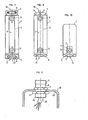
- the housing 1 shown in the drawing is essentially designed as a tube.
- the tube wall of the housing 1 has a thickened wall part 2 (FIG. 2) on one longitudinal side, so that a projecting longitudinal web is formed which has a flat surface 3 on the outside.
- an internal thread 4 is formed, into which a locking screw designed as a sleeve screw 5 can be screwed.
- the sleeve screw 5 has a head 7 provided with wrench surfaces 6 and a recess 8 designed as a circumferential groove.
- a locking screw 9 is provided at the end region of the housing 1, which radially in the recess 8 of the sleeve screw 5 engages.
- the locking screw 9 is mounted in a stepped transverse hole 10, which is located in the area of the thickened wall part 2.
- the locking screw 9 can be designed so that it can only be loosened with a special tool. In addition, it is favorable to secure the locking screw 9 in the released position on the housing 1.
- a threaded hole 11 is also provided, into which an earth connection screw can be screwed.
- the threaded hole 11 is also located in the thickened wall part 2 in the area between two notches 12.
- the housing 1 can be conveniently one at each of the two opposite end regions Have sleeve screw 5 through cable entry 13, so that a corresponding cable connection can be made from both sides.
- the in FIG. 3 shown housing 1 has only a single cable entry 13 and is otherwise designed as a closed heating cable termination.
- housing 1 are essentially like the housing 1 of FIG. 1 and 2, however, the sleeve screws 5 used here have a strain relief 14 for fixing the cable, by means of a corresponding clamp fastening being achieved by means of screws.
- the housing 1 is assigned elastomer seals 15 which can be used in the area of the internal thread 4 of the housing 1.
- the elastomer seal 15 consists of a high-temperature resistant material, such as silicone or the like, and has a permanent temperature resistance, which is preferably substantially above 150 ° C.
- the elastomer seal 15 is located between a stop washer 16 which is supported in the housing 1 and a pressure washer 17 which bears against the sleeve screw 5.
- the FIG. 7 clearly shows that an insulating sheath 18 is provided in the metallic housing 1 is designed as a thin-walled tubular sleeve in this embodiment.
- the insulating jacket 18 consists of a high-temperature-resistant insulating material, which can be a thermosetting plastic, for example, and comprises an insulating body 19 which is closely enclosed by the insulating jacket 18.
- the insulating body 19 is thus located in the interior 20 of the insulating sheath 18.
- This interior 20 is not filled with a casting resin or the like, as is usually the case, but is completely free from casting, so that the insulating body 19 is detachably mounted. There is therefore a free volume 21 on each side of the insulating body 19, which is also delimited by the end region of the insulating sheath 18 projecting beyond the insulating body 19.
- connection terminals 24 for electrical cable conductors and a protective conductor connection 25 to which a protective conductor 26 can be connected are connected to which a protective conductor 26 can be connected.
- a stair-step-shaped air and creepage distance 27 is formed on the insulating body 19 on one end face 22 between the area of the connecting terminals 24 and the protective conductor connection 25.
- the tubular insulating jacket 18 is supported at one end on a collar 28 of the housing 1.
- the stop disk 16 lies on the other side of the collar 28.
- the insulating sheath 18 is supported by the stop disc 16, which is designed here in steps.
- the FIG. 7 is also It can be seen that the insulating jacket 18 has an opening 29 in its peripheral wall in which an electrically conductive spring clip 30 is located.
- the spring clip 30 is arranged on the protective conductor connection 25 and is in contact with the inner surface 31 of the metallic housing 1, so that a perfect connection is established.
- the housing 1 is so small that the total free volume 21 is extremely small and is preferably less than ten cubic centimeters.
- the free volume 21 is also less than a third of the total volume of the interior 20 in the housing 1.
- This housing 1 is designed according to the invention as a pressure-resistant encapsulation for perfect explosion protection even at high operating temperatures. An explosion of an explosive mixture that may occur in the interior 20 is thus reliably resisted even at elevated heating temperatures, so that transmission of the explosion from the interior 20 to the atmosphere surrounding the housing 1 is reliably prevented.
- a heating cable 32 is inserted through the upper cable entry 13 into the housing 1, the end part 33 of which is passed through the sleeve screw 5 and passes through the elastomer seal 15 as well as the pressure plate 17 and stop plate 18.
- the elastomer seal 15 is firmly pressed against the end part 33 of the heating cable 32.
- the temperature-resistant elastomer seal 15 is releasably secured to form an ignition-proof gap 34 in the opening 35 of the housing 1 via the clamped sleeve screw 5.
- the thickness of the elastomer seal 15 and thus the length of the ignition-proof gap 34 is carried out depending on the size of the free volume 21 in the housing 1, so that in any case a perfect explosion-proof introduction of the heating cable 32, which heats up to about 115 ° C. and more, is ensured.
- a cable 36 is provided here, the conductor 37, the conductors 37 of which are also detachably fastened to the connecting terminals 24 and to the protective conductor connection 25 of the insulating body 19.
- the connecting cable 36 like the heating cable 32, is inserted into the housing 1 in a manner that prevents ignition. It is within the scope of the invention to provide a second heating cable 32 instead of the connecting cable 36 on the lower cable entry 13.
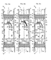
- the housing 1 of FIG. 8 to 14 made of a temperature-resistant insulating material, preferably of a thermosetting plastic, so that no protective conductor needs to be connected to the outside.
- the housing 1 is also designed as a pressure-resistant encapsulation in such a way that reliable explosion protection is guaranteed in any case even at high operating temperatures of the heating cable 32. Since the housing 1 consists entirely of an insulating material, the insulating jacket 18 in this case is formed directly by the wall of the housing 1 itself. The inner surface 31 of the housing 1 thus closely encloses the insulating body 19. In this embodiment, the insulating sheath 18 is therefore a component of the pressure-resistant plastic housing 1 that is integrated in one piece from the same material.
- FIG. 9 shows that the pressure-resistant housing 1 can also be arranged directly on a connection housing 38, for example.
- the sleeve screw 5 of the one cable entry 13 has a threaded tube 39 which passes through the wall of the connection housing 38.
- the threaded tube 39 is fixed with a threaded nut 41, so that here, too, an ignition-arrest-proof arrangement is made.
- the connection cable 36 projects into the connection housing 38.
- FIG. 14 it can be seen that the two sleeve screws 5 of the housing 1 are each assigned an anti-rotation bracket 42.
- the anti-rotation bracket 42 which is shown in FIG. 16 and 16 a is again shown separately, lies with a flat surface 43 on the flat surface 3 of the wall part 2.
- a right-angled bracket end 44 is located close to one of the wrench flats 6 of the head 7.
- the anti-rotation bracket 42 is expediently fixed to the housing 1 with the locking screw 9, the locking screw 9 advantageously being embedded in an enlarged stepped bore of the anti-rotation bracket 2.
- the anti-rotation bracket 42 has a locking pin 45 which engages in a bore 46 of the wall part 2 for a correct rotation-proof locking.
- the FIG. 17 it can be seen that the housing 1 has, next to the one flat surface 3, a second flat surface 3 'which is oriented at an angle to it and which is likewise formed on the thickened wall part 2.
- the second plane surface 3 ' also has a transverse hole 10 for the locking screw 9 and a bore 46 for the locking pin 45, so that a second parallel anti-rotation bracket 42 can be attached.
- the in the FIG. 15, 15a and 15b separately shown sleeve screw 5 also has a strain relief 14, which consists of a base web 47 and two clamping webs 48, 48 ', which are braced against one another by means of screws 49, the heating cable 32 being held between the clamping webs 48, 48' becomes.
- FIG. 7a shown embodiment is essentially like that of FIG. 7 executed.
- a single-core heating cable 32 is enclosed in the heating cable entry 13.
- the only heating cable conductor of this single-core heating cable is attached to the connection terminal 24.
- two single-core heating cables 32 are fastened together in the heating cable entry 13.
- the two heating cables of the single-core heating cable 32 are connected to one or two terminals 24 of the insulating body 19.
- FIG. 7c shows that the insulating body 19 in the pressure-resistant housing 1 consists of an upper plug part 58 and a lower plug part 58 ', which are plugged together.
- the two plug parts 58, 58 ' can be plugged together during assembly outside the housing 1 or also in the housing 1.
- This two-part connector design of the insulating body 19, in particular, makes it considerably easier to connect the heating cable 32 or the connecting cable 36.
- the two facing ends 59 of the connector parts 58, 58 ' are designed in a stepped manner so that they engage in one another, which provides positive guidance, anti-rotation protection and a longer insulating distance in the coupling area.
- the recess 8 in the upper and lower sleeve screw 5 is designed as an axial groove for the engagement of the locking screw.
- two opposing axial grooves are provided on the circumference of the sleeve screw 5.
- the axial grooves can extend over the entire length of the sleeve or, as shown, can be made somewhat shorter.
- any tolerances (cable circumference or diameter, elastomer seal 15) in the area of the heating cable entry 13 can be compensated for properly, since a finely graduated securing of the sleeve screw 5 can be achieved over a larger adjustment range in the axial direction.
- FIG. 13a, 13b and 13c are roughly like the examples of FIG. 7a, 7b and 7c, only that here a pressure-resistant plastic housing is provided instead of the pressure-resistant metallic housing.
- a single-core heating cable 32 is connected.
- a two-core connecting cable 36 is provided on the opposite side.
- two single-core heating cables 32 are fixed together in the upper heating cable entry 13 and connected to the insulating body 19.
- the insulating body 19 has two plug parts 58, 58 'which are plugged together, the mutually facing end faces 59 of which are stepped and interlock.
- the FIG. 18 shows an arrangement of the device according to the invention on a product tube 50 which is heated with the self-regulating heating cable 32, which here is preferably designed as a flat strip and is spirally wound around the product tube 50.
- the passage in the elastomer seal 15 of the heating cable entry 13 is preferably essentially formed as a narrow slot, so that a tight seal is ensured.
- the pressure-resistant housing 1 is fastened to the product tube 50 with a clamp band 51 and is thereby located within an insulation 52 which surrounds the product tube 50.
- the opposite to the heating cable 32 on the other side inserted into the housing 1 connecting cable 36 is in a bushing 53 led out of the insulation 52 to the outside.
- the bushing 53 is screwed to a bracket 54, which is fixed to the product tube 50 with a collar 55.
- the bushing 53 is sealed on the outside of an outer shell 56 of the insulation 52 with an elastic seal 57 on its circumference.
- FIG. 19 shows an arrangement in which the pressure-resistant housing 1 is provided essentially outside the insulation 52.
- the housing 1 is also attached to the product tube 50 with a bracket 54.
- the lower cable entry 13 passes through the outer casing 56 and projects into the insulation 52, the housing on the outer circumference being sealed to the outer casing 56 with the elastic seal 57.
- the heating cable 32 likewise embodied here as a flat heating tape, lies directly against the product tube 50 for good heat transfer.
- a major advantage of the heating tape connection device according to the invention is that no separate national approvals have to be obtained in the different countries, but that with this flameproof encapsulated heating tape connection an explosion protection permit that is effective in many countries is ensured at the same time. It is also advantageous that the explosion-proof heating tape connection according to the invention is easily accessible at any time, for example for an inspection or the like, if necessary.
- heating cables 32 can be connected, which are designed, for example, as self-regulating parallel heating tapes, as parallel resistance heating tapes or as single-core plastic heating cables. It is also possible to use differently designed insulation materials, such as silicone, Teflon, polyolefins or the like, which is not possible with the known heating tape terminations to be filled with casting resin, because a sealing connection between a casting resin system and different cable insulation cannot be carried out uniformly.
- a heating cable 32 which has no protective braid on the outside.
- the use of such a braidless heating cable 32 is particularly advantageous in the device according to the invention if, for example, a mechanically protected laying of the heating cable 32 takes place in a pipe or the like or if a protective low voltage (less than 42 volts) is used.
- a single-core heating cable 32 can also advantageously be laid as a loop in such a way that the two end parts of the heating cable 32 can be connected in one and the same heating cable connection housing or heating cable connection housing.
- the two end parts of the heating cable 32 are advantageously connected to one side of the housing 1 (FIGS. 7b and 7c), while the connecting cable 36 is on the other side. This has the advantage that no return conductor or a second connection is required.
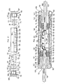
- FIGS. 20 and 21 has a housing 101, preferably made of temperature-resistant plastic, which is tubular and has an internal thread 104 at each of the opposite end regions.
- a sleeve screw 105 can be screwed into the two internal threads 104 on both ends of the housing 101.
- Each sleeve screw 105 has a head 107 which is provided with flats 106 designed as flats.
- the sleeve screw 105 also has an external thread 108 which extends up to the head 107 and which engages in the internal thread 104 of the housing 101.
- the housing 101 shown here has at the opposite end regions each a cable entry 113 passing through the sleeve screw 105, through which a heating cable 132 is inserted in the housing 101 in such a way that it is flame-proof so that an extension of the heating cable corresponding to the respective requirements is possible with simple means .
- Each of the two cable entries 113 has an elastomer seal 115, a stop disc 116 and a pressure disc 117.
- the elastomer seal 115 is located between the stop washer 116 and the pressure washer 117.
- the pressure washer 117 bears against the thread-side end of the sleeve screw 105, while the step-like shouldered stop washer 116 is supported on a collar 128 formed on the inner wall of the housing 101.
- the elastomer seal 115 consists of a high-temperature resistant material, such as silicone or the like, and has a permanent temperature resistance, which is preferably substantially above 150 ° C.
- the housing 101 which is preferably made of a thermosetting plastic, is designed to be temperature-resistant as a pressure-resistant encapsulation in such a way that perfect explosion protection is guaranteed even at high operating temperatures of the heating cables 132. Since the housing 101 consists entirely of an electrically insulating material, no additional insulating sheath is required in the interior 120, in which an insulating body 119 is located. The inner surface 131 of the housing 101 designed as an insulating sheath 118 encloses the insulating body 119.
- the interior 120 is not filled with a casting resin or the like, as is usually the case, but is completely free from casting, so that the insulating body 119 is detachably mounted in the interior 120. Thus, in the interior 120 on both end faces 122 of the insulating body 119 there is a free volume 121 not filled with potting compound or the like, which is also delimited on the opposite side by the pressure disk 116.
- the insulating body 119 has protective conductor connections 125 to which the protective conductors 126 of the heating cables 132 inserted into the housing 101 from both sides are connected.
- the insulating body 119 has terminals 124 to which the end parts 133 of the two heating cables 132 are connected.
- it can also be expedient to insert a heating cable 132 in such a way that it cannot ignite against ignition and only on one of the two cable entries 113, and to connect it to the insulating body 119, while no heating cable, but an electrical connection cable is introduced in the other opposite cable entry 113 and can be connected to the insulating body 119.
- an air and creepage distance 127 is provided on the two opposite end faces 122 of the insulating body 119, which is designed as a step-like gradation.
- the insulating body 119 is supported with its right end face 122 in the drawing on a shoulder 123 formed on the inner surface 131 of the housing 101.
- the housing 101 itself is designed to be relatively small in order to keep the total free volume 121 as small as possible and below ten cubic centimeters, the free volume 121 also being less than a third of the entire interior 120.
- the housing 101 designed as a pressure-resistant encapsulation, is made of a high-temperature-resistant insulating material, so that even at high operating temperatures of e.g. A perfect explosion protection is guaranteed at 130 ° and more. An explosion of an explosive mixture that may occur in the interior 120 is thus reliably resisted even at high heating temperatures. A transfer of the explosion from the interior 120 to the atmosphere surrounding the housing 101 is thereby reliably prevented.
- the heating cable 132 passed through the sleeve screw 105, the thrust washer 117, the elastomer seal 115 and the stop washer 116 is firmly clamped in the cable entry 113, wherein the elastomer seal 115 is pressed firmly against the circumference of the heating cable 132 via the prestressing force of the sleeve screw 105.
- the temperature-resistant elastomer seal 115 is detachably fixed in the opening 135 of the housing 101 by means of the tightly tightened sleeve screw 105, an ignition-resistant gap 134 being formed on the circumference of the elastomer seal 115, which in the area of the circumferential surfaces of the pressure plate 117 and the stop plate 116 in axial direction can preferably be extended.
- the length of the explosion-proof gap 134 is designed in accordance with the size of the free volume 121 in the housing 101, so that a high explosion protection corresponding to the respective requirements is ensured in any case.
- the two sleeve screws 105 are each assigned an anti-rotation bracket 142, which ensure that the two sleeve screws 105 of the fully assembled cable entries 113 are secured against unintentional loosening.
- this anti-rotation bracket 142 can have a fastening part 109, a securing web 110, a holding web 111 and a nose 112.
- VerFstoffbügel is executed 142 of uniform material in one piece as produced from a sheet metal stamped and bent part, whereby a very simple and inexpensive manufacture mög "is Lich.
- the fastening part 109 of the anti-rotation bracket 142 is here advantageously designed as a circular ring part which surrounds the external thread 108 of the sleeve screw 105 and abuts the head 107 thereof.
- the ring-shaped fastening part 109 and the holding web 111 which is rectangular in cross section are oriented approximately at right angles to one another, the holding web 111 resting with its one surface 143 on the flat surface 103 formed on the outer circumference of the housing 101.
- the nose 112 is formed, which is bent at right angles from the holding web 111 in the direction of the housing 101 and engages in a hole 146 in the housing 101.
- the securing web 110 is formed on the side of the annular fastening part 109 opposite the holding web 111 and extends in the non-final assembly position transversely to the axis 160 of the housing 101.
- the securing web 110 of the two anti-rotation brackets 142 is bent so that it extends approximately parallel to the axis 160 and lies flat against the wrench surface 106 of the sleeve screw 105, whereby the sleeve screw 105 is secured against unintentional rotation.
- the securing web 110 is roughly in the plane of the Fastening part 109 bent back so that the sleeve screw 105 can be loosened.
Landscapes
- Cable Accessories (AREA)
- Connector Housings Or Holding Contact Members (AREA)
- Processing Of Terminals (AREA)
Priority Applications (1)
| Application Number | Priority Date | Filing Date | Title |
|---|---|---|---|
| AT86100003T ATE42885T1 (de) | 1985-01-05 | 1986-01-02 | Elektrische heizkabelanschlubvorrichtung. |
Applications Claiming Priority (2)
| Application Number | Priority Date | Filing Date | Title |
|---|---|---|---|
| DE3500232A DE3500232C1 (de) | 1985-01-05 | 1985-01-05 | Einrichtung fuer ein elektrisches Heizkabel |
| DE3500232 | 1985-01-05 |
Publications (3)
| Publication Number | Publication Date |
|---|---|
| EP0187636A1 true EP0187636A1 (fr) | 1986-07-16 |
| EP0187636B1 EP0187636B1 (fr) | 1989-05-03 |
| EP0187636B2 EP0187636B2 (fr) | 1993-12-29 |
Family
ID=6259317
Family Applications (1)
| Application Number | Title | Priority Date | Filing Date |
|---|---|---|---|
| EP86100003A Expired - Lifetime EP0187636B2 (fr) | 1985-01-05 | 1986-01-02 | Dispositif de connexion pour un câble chauffant |
Country Status (3)
| Country | Link |
|---|---|
| EP (1) | EP0187636B2 (fr) |
| AT (1) | ATE42885T1 (fr) |
| DE (2) | DE3500232C1 (fr) |
Cited By (10)
| Publication number | Priority date | Publication date | Assignee | Title |
|---|---|---|---|---|
| WO1990006604A1 (fr) * | 1988-12-08 | 1990-06-14 | Raychem Corporation | Connecteur pour appareil de chauffage electrique |
| DE19726418A1 (de) * | 1997-06-23 | 1999-01-28 | Daimler Benz Aerospace Airbus | Heizleiter-Verbindungssystem |
| WO1999027615A1 (fr) * | 1997-11-22 | 1999-06-03 | Reinhold Barlian | Dispositif permettant de connecter et de raccorder un cable |
| EP0893857A3 (fr) * | 1997-06-23 | 2000-04-12 | DaimlerChrysler Aerospace Airbus Gesellschaft mit beschränkter Haftung | Systeme de connexion pour conducteur de chauffage dans un avion |
| US6423952B1 (en) | 1999-10-09 | 2002-07-23 | Airbus Deutschland Gmbh | Heater arrangement with connector or terminating element and fluoropolymer seal, and method of making the same |
| EP1313351A1 (fr) * | 2001-11-16 | 2003-05-21 | Thermon Europe B.V. | Manchon de jonction pour câbles chauffants |
| WO2014040772A1 (fr) * | 2012-09-14 | 2014-03-20 | Phoenix Contact Gmbh & Co. Kg | Structure d'étanchéité à manchon |
| CN108593698A (zh) * | 2018-03-20 | 2018-09-28 | 饶榕琦 | 一种地热电缆制造用加热装置 |
| CN110416936A (zh) * | 2019-08-08 | 2019-11-05 | 常州市沃科科技有限公司 | 一种防火防爆隔热毯、电缆、电缆接头及电缆铺设结构 |
| CN115021196A (zh) * | 2022-06-06 | 2022-09-06 | 国网河南省电力公司邓州市供电公司 | 一种应用于电缆连接处的防火爆装置 |
Families Citing this family (3)
| Publication number | Priority date | Publication date | Assignee | Title |
|---|---|---|---|---|
| DE3639485A1 (de) * | 1986-11-18 | 1988-05-26 | Karl Kapfer | Explosionsgeschuetztes elektrisches geraet |
| DE4108901C2 (de) * | 1991-03-19 | 1994-12-01 | Reinhold Barlian | Einrichtung zum Anschließen und Verbinden einer elektrischen Leitung |
| DE10219019B3 (de) * | 2002-04-27 | 2004-01-15 | Bartec Componenten Und Systeme Gmbh | Einrichtung zur Verbindung zweier elektrischer Kabel |
Citations (8)
| Publication number | Priority date | Publication date | Assignee | Title |
|---|---|---|---|---|
| US2046102A (en) * | 1931-07-30 | 1936-06-30 | Gen Electric | Electric terminal connection |
| US2269194A (en) * | 1939-12-19 | 1942-01-06 | Gen Electric | Electric heater |
| FR1244373A (fr) * | 1959-09-14 | 1960-10-28 | Nec | Perfectionnements aux systèmes de raccordement électrique des éléments chauffants blindés |
| DE1440855A1 (de) * | 1963-10-15 | 1968-11-14 | Oskar Biegel Gmbh | Wasser- und gasdichte Schnellverbindungsmuffe fuer elektrische Kabel |
| DE2011392A1 (de) * | 1970-03-11 | 1971-09-23 | Karl Henning & Co | Elektrische Heizkabelanordnung |
| FR2221061A7 (en) * | 1973-03-07 | 1974-10-04 | Thermo Controle | Connections to ground resistance heating elements - have junction box and ground contact area used to dissipate heat |
| DE2549158A1 (de) * | 1974-11-06 | 1976-05-20 | Elcalor Ag | Heizkoerper fuer die elektrische weichenheizung |
| US4388523A (en) * | 1981-06-10 | 1983-06-14 | Multistress, Inc. | Electrical heating cable connector |
-
1985
- 1985-01-05 DE DE3500232A patent/DE3500232C1/de not_active Expired
-
1986
- 1986-01-02 EP EP86100003A patent/EP0187636B2/fr not_active Expired - Lifetime
- 1986-01-02 AT AT86100003T patent/ATE42885T1/de active
- 1986-01-02 DE DE8686100003T patent/DE3663222D1/de not_active Expired
Patent Citations (8)
| Publication number | Priority date | Publication date | Assignee | Title |
|---|---|---|---|---|
| US2046102A (en) * | 1931-07-30 | 1936-06-30 | Gen Electric | Electric terminal connection |
| US2269194A (en) * | 1939-12-19 | 1942-01-06 | Gen Electric | Electric heater |
| FR1244373A (fr) * | 1959-09-14 | 1960-10-28 | Nec | Perfectionnements aux systèmes de raccordement électrique des éléments chauffants blindés |
| DE1440855A1 (de) * | 1963-10-15 | 1968-11-14 | Oskar Biegel Gmbh | Wasser- und gasdichte Schnellverbindungsmuffe fuer elektrische Kabel |
| DE2011392A1 (de) * | 1970-03-11 | 1971-09-23 | Karl Henning & Co | Elektrische Heizkabelanordnung |
| FR2221061A7 (en) * | 1973-03-07 | 1974-10-04 | Thermo Controle | Connections to ground resistance heating elements - have junction box and ground contact area used to dissipate heat |
| DE2549158A1 (de) * | 1974-11-06 | 1976-05-20 | Elcalor Ag | Heizkoerper fuer die elektrische weichenheizung |
| US4388523A (en) * | 1981-06-10 | 1983-06-14 | Multistress, Inc. | Electrical heating cable connector |
Cited By (16)
| Publication number | Priority date | Publication date | Assignee | Title |
|---|---|---|---|---|
| WO1990006604A1 (fr) * | 1988-12-08 | 1990-06-14 | Raychem Corporation | Connecteur pour appareil de chauffage electrique |
| US6126483A (en) * | 1997-06-23 | 2000-10-03 | Daimlerchrysler Aerospace Airbus Gmbh | Interconnect system for heating conductors in an aircraft |
| DE19726418A1 (de) * | 1997-06-23 | 1999-01-28 | Daimler Benz Aerospace Airbus | Heizleiter-Verbindungssystem |
| US5998772A (en) * | 1997-06-23 | 1999-12-07 | Daimlerchrysler Aerospace Airbus Gmbh | Interconnect system for heating conductors |
| EP0893844A3 (fr) * | 1997-06-23 | 2000-04-12 | DaimlerChrysler Aerospace Airbus Gesellschaft mit beschränkter Haftung | Systeme de connexion pour conducteur de chauffage |
| EP0893857A3 (fr) * | 1997-06-23 | 2000-04-12 | DaimlerChrysler Aerospace Airbus Gesellschaft mit beschränkter Haftung | Systeme de connexion pour conducteur de chauffage dans un avion |
| US6520800B1 (en) | 1997-11-22 | 2003-02-18 | Bartec Componenten Und Systeme Gmbh | Device for linking and connecting a line |
| WO1999027615A1 (fr) * | 1997-11-22 | 1999-06-03 | Reinhold Barlian | Dispositif permettant de connecter et de raccorder un cable |
| US6423952B1 (en) | 1999-10-09 | 2002-07-23 | Airbus Deutschland Gmbh | Heater arrangement with connector or terminating element and fluoropolymer seal, and method of making the same |
| EP1313351A1 (fr) * | 2001-11-16 | 2003-05-21 | Thermon Europe B.V. | Manchon de jonction pour câbles chauffants |
| WO2014040772A1 (fr) * | 2012-09-14 | 2014-03-20 | Phoenix Contact Gmbh & Co. Kg | Structure d'étanchéité à manchon |
| CN108593698A (zh) * | 2018-03-20 | 2018-09-28 | 饶榕琦 | 一种地热电缆制造用加热装置 |
| CN108593698B (zh) * | 2018-03-20 | 2020-11-20 | 浙江启博知识产权运营有限公司 | 一种地热电缆制造用加热装置 |
| CN110416936A (zh) * | 2019-08-08 | 2019-11-05 | 常州市沃科科技有限公司 | 一种防火防爆隔热毯、电缆、电缆接头及电缆铺设结构 |
| CN115021196A (zh) * | 2022-06-06 | 2022-09-06 | 国网河南省电力公司邓州市供电公司 | 一种应用于电缆连接处的防火爆装置 |
| CN115021196B (zh) * | 2022-06-06 | 2023-07-25 | 国网河南省电力公司邓州市供电公司 | 一种应用于电缆连接处的防火爆装置 |
Also Published As
| Publication number | Publication date |
|---|---|
| DE3500232C1 (de) | 1986-08-14 |
| EP0187636B1 (fr) | 1989-05-03 |
| DE3663222D1 (en) | 1989-06-08 |
| EP0187636B2 (fr) | 1993-12-29 |
| ATE42885T1 (de) | 1989-05-15 |
Similar Documents
| Publication | Publication Date | Title |
|---|---|---|
| EP2382693B1 (fr) | Dispositif de fixation pour fixer un câble sur un passage de boîtier | |
| EP1034583B1 (fr) | Dispositif permettant de connecter et de raccorder un cable | |
| DE69734971T2 (de) | Koaxialkabelverbinder | |
| EP0187636B1 (fr) | Dispositif de connexion pour un câble chauffant | |
| EP1552582B1 (fr) | Connecteur electrique enfichable | |
| DE10141052A1 (de) | Steckerverbindung | |
| EP0527368B1 (fr) | Dispositif pour traversée de câble | |
| DE3002651A1 (de) | Befestigung fuer ein laengliches elektrisch leitendes element und verfahren zum verbinden zweier laenglicher elektrisch leitender elemente | |
| DE3308332C2 (fr) | ||
| DE4225267C3 (de) | Abdichtungsvorrichtung für ein elektronisches Schaltgerät | |
| EP0505911B1 (fr) | Dispositif pour une conduite électrique | |
| DD156210A1 (de) | Universalmuffe fuer fernmelde-bzw.starkstromkabel | |
| CH690946A5 (de) | Anschlusselement für abgeschirmte Leiter und/oder Kabel. | |
| EP0187203A2 (fr) | Distributeur ou dérivation pour câbles coaxiaux de communication à large bande | |
| DE3221111C2 (de) | Explosions- oder schlagwettergeschützte elektrische Kupplungssteckvorrichtung | |
| DE2733815A1 (de) | Sperr- oder uebergangsmuffe fuer hochspannungskabel | |
| DE2730814C3 (de) | Abschlussvorrichtung in Explosionsschutzausführung für ein Heizband | |
| DE2659234C3 (de) | Kabelgarnitur zum Anschluß eines geschirmten, kunststoffisolierten Starkstromkabels an ein elektrisches Gerät | |
| DE29611451U1 (de) | Anschlußelement zur Verbindung eines elektrisch leitenden Abschirmmantels mit einer Verschraubung | |
| DE9103365U1 (de) | Rohrförmige Gehäuseeinrichtung für eine elektrische Leitung | |
| CH648160A5 (de) | Verbindungs- und verteilerdose fuer fernmeldekabel. | |
| EP0875736A1 (fr) | Partie d'un boítier avec un connecteur intégré | |
| DE3413452A1 (de) | Grenztaster | |
| DE202019101084U1 (de) | Anschlusseinrichtung | |
| DE2653440A1 (de) | Apparateklemme |
Legal Events
| Date | Code | Title | Description |
|---|---|---|---|
| PUAI | Public reference made under article 153(3) epc to a published international application that has entered the european phase |
Free format text: ORIGINAL CODE: 0009012 |
|
| 17P | Request for examination filed |
Effective date: 19860110 |
|
| AK | Designated contracting states |
Kind code of ref document: A1 Designated state(s): AT BE CH DE FR GB IT LI NL SE |
|
| 17Q | First examination report despatched |
Effective date: 19880630 |
|
| GRAA | (expected) grant |
Free format text: ORIGINAL CODE: 0009210 |
|
| AK | Designated contracting states |
Kind code of ref document: B1 Designated state(s): AT BE CH DE FR GB IT LI NL SE |
|
| PG25 | Lapsed in a contracting state [announced via postgrant information from national office to epo] |
Ref country code: IT Free format text: LAPSE BECAUSE OF FAILURE TO SUBMIT A TRANSLATION OF THE DESCRIPTION OR TO PAY THE FEE WITHIN THE PRE;WARNING: LAPSES OF ITALIAN PATENTS WITH EFFECTIVE DATE BEFORE 2007 MAY HAVE OCCURRED AT ANY TIME BEFORE 2007. THE CORRECT EFFECTIVE DATE MAY BE DIFFERENT FROM THE ONE RECORDED.SCRIBED TIME-LIMIT Effective date: 19890503 Ref country code: GB Effective date: 19890503 Ref country code: SE Effective date: 19890503 |
|
| REF | Corresponds to: |
Ref document number: 42885 Country of ref document: AT Date of ref document: 19890515 Kind code of ref document: T |
|
| REF | Corresponds to: |
Ref document number: 3663222 Country of ref document: DE Date of ref document: 19890608 |
|
| ET | Fr: translation filed | ||
| GBV | Gb: ep patent (uk) treated as always having been void in accordance with gb section 77(7)/1977 [no translation filed] | ||
| PG25 | Lapsed in a contracting state [announced via postgrant information from national office to epo] |
Ref country code: AT Effective date: 19900102 |
|
| PLBI | Opposition filed |
Free format text: ORIGINAL CODE: 0009260 |
|
| 26 | Opposition filed |
Opponent name: RAYCHEM LIMITED Effective date: 19900202 |
|
| NLR1 | Nl: opposition has been filed with the epo |
Opponent name: RACHEM LIMITED |
|
| PUAH | Patent maintained in amended form |
Free format text: ORIGINAL CODE: 0009272 |
|
| STAA | Information on the status of an ep patent application or granted ep patent |
Free format text: STATUS: PATENT MAINTAINED AS AMENDED |
|
| 27A | Patent maintained in amended form |
Effective date: 19931229 |
|
| AK | Designated contracting states |
Kind code of ref document: B2 Designated state(s): AT BE CH DE FR GB IT LI NL SE |
|
| REG | Reference to a national code |
Ref country code: CH Ref legal event code: AEN |
|
| NLR2 | Nl: decision of opposition | ||
| ET3 | Fr: translation filed ** decision concerning opposition | ||
| NLR3 | Nl: receipt of modified translations in the netherlands language after an opposition procedure | ||
| PGFP | Annual fee paid to national office [announced via postgrant information from national office to epo] |
Ref country code: BE Payment date: 19971204 Year of fee payment: 13 |
|
| PGFP | Annual fee paid to national office [announced via postgrant information from national office to epo] |
Ref country code: DE Payment date: 19990118 Year of fee payment: 14 |
|
| PG25 | Lapsed in a contracting state [announced via postgrant information from national office to epo] |
Ref country code: BE Free format text: LAPSE BECAUSE OF NON-PAYMENT OF DUE FEES Effective date: 19990131 |
|
| PGFP | Annual fee paid to national office [announced via postgrant information from national office to epo] |
Ref country code: CH Payment date: 19990211 Year of fee payment: 14 |
|
| BERE | Be: lapsed |
Owner name: BARLIAN REINHOLD Effective date: 19990131 |
|
| PGFP | Annual fee paid to national office [announced via postgrant information from national office to epo] |
Ref country code: FR Payment date: 19991230 Year of fee payment: 15 |
|
| PG25 | Lapsed in a contracting state [announced via postgrant information from national office to epo] |
Ref country code: CH Free format text: LAPSE BECAUSE OF NON-PAYMENT OF DUE FEES Effective date: 20000131 Ref country code: LI Free format text: LAPSE BECAUSE OF NON-PAYMENT OF DUE FEES Effective date: 20000131 |
|
| PGFP | Annual fee paid to national office [announced via postgrant information from national office to epo] |
Ref country code: NL Payment date: 20000131 Year of fee payment: 15 |
|
| REG | Reference to a national code |
Ref country code: CH Ref legal event code: PL |
|
| PG25 | Lapsed in a contracting state [announced via postgrant information from national office to epo] |
Ref country code: DE Free format text: LAPSE BECAUSE OF NON-PAYMENT OF DUE FEES Effective date: 20001101 |
|
| PG25 | Lapsed in a contracting state [announced via postgrant information from national office to epo] |
Ref country code: NL Free format text: LAPSE BECAUSE OF NON-PAYMENT OF DUE FEES Effective date: 20010801 |
|
| PG25 | Lapsed in a contracting state [announced via postgrant information from national office to epo] |
Ref country code: FR Free format text: LAPSE BECAUSE OF NON-PAYMENT OF DUE FEES Effective date: 20010928 |
|
| NLV4 | Nl: lapsed or anulled due to non-payment of the annual fee |
Effective date: 20010801 |
|
| REG | Reference to a national code |
Ref country code: FR Ref legal event code: ST |