EP0187645A2 - Ventilateur centrifuge opposé sur une ligne et équilibré - Google Patents
Ventilateur centrifuge opposé sur une ligne et équilibré Download PDFInfo
- Publication number
- EP0187645A2 EP0187645A2 EP86100069A EP86100069A EP0187645A2 EP 0187645 A2 EP0187645 A2 EP 0187645A2 EP 86100069 A EP86100069 A EP 86100069A EP 86100069 A EP86100069 A EP 86100069A EP 0187645 A2 EP0187645 A2 EP 0187645A2
- Authority
- EP
- European Patent Office
- Prior art keywords
- blower
- shaft
- housing
- impeller
- plate
- Prior art date
- Legal status (The legal status is an assumption and is not a legal conclusion. Google has not performed a legal analysis and makes no representation as to the accuracy of the status listed.)
- Withdrawn
Links
Images






Classifications
-
- F—MECHANICAL ENGINEERING; LIGHTING; HEATING; WEAPONS; BLASTING
- F04—POSITIVE - DISPLACEMENT MACHINES FOR LIQUIDS; PUMPS FOR LIQUIDS OR ELASTIC FLUIDS
- F04D—NON-POSITIVE-DISPLACEMENT PUMPS
- F04D29/00—Details, component parts, or accessories
- F04D29/40—Casings; Connections of working fluid
- F04D29/42—Casings; Connections of working fluid for radial or helico-centrifugal pumps
- F04D29/4206—Casings; Connections of working fluid for radial or helico-centrifugal pumps especially adapted for elastic fluid pumps
- F04D29/4226—Fan casings
- F04D29/424—Double entry casings
-
- F—MECHANICAL ENGINEERING; LIGHTING; HEATING; WEAPONS; BLASTING
- F04—POSITIVE - DISPLACEMENT MACHINES FOR LIQUIDS; PUMPS FOR LIQUIDS OR ELASTIC FLUIDS
- F04D—NON-POSITIVE-DISPLACEMENT PUMPS
- F04D17/00—Radial-flow pumps, e.g. centrifugal pumps; Helico-centrifugal pumps
- F04D17/08—Centrifugal pumps
- F04D17/16—Centrifugal pumps for displacing without appreciable compression
- F04D17/162—Double suction pumps
-
- F—MECHANICAL ENGINEERING; LIGHTING; HEATING; WEAPONS; BLASTING
- F04—POSITIVE - DISPLACEMENT MACHINES FOR LIQUIDS; PUMPS FOR LIQUIDS OR ELASTIC FLUIDS
- F04D—NON-POSITIVE-DISPLACEMENT PUMPS
- F04D25/00—Pumping installations or systems
- F04D25/16—Combinations of two or more pumps ; Producing two or more separate gas flows
- F04D25/166—Combinations of two or more pumps ; Producing two or more separate gas flows using fans
-
- F—MECHANICAL ENGINEERING; LIGHTING; HEATING; WEAPONS; BLASTING
- F04—POSITIVE - DISPLACEMENT MACHINES FOR LIQUIDS; PUMPS FOR LIQUIDS OR ELASTIC FLUIDS
- F04D—NON-POSITIVE-DISPLACEMENT PUMPS
- F04D29/00—Details, component parts, or accessories
- F04D29/26—Rotors specially for elastic fluids
- F04D29/28—Rotors specially for elastic fluids for centrifugal or helico-centrifugal pumps for radial-flow or helico-centrifugal pumps
- F04D29/281—Rotors specially for elastic fluids for centrifugal or helico-centrifugal pumps for radial-flow or helico-centrifugal pumps for fans or blowers
-
- F—MECHANICAL ENGINEERING; LIGHTING; HEATING; WEAPONS; BLASTING
- F04—POSITIVE - DISPLACEMENT MACHINES FOR LIQUIDS; PUMPS FOR LIQUIDS OR ELASTIC FLUIDS
- F04D—NON-POSITIVE-DISPLACEMENT PUMPS
- F04D29/00—Details, component parts, or accessories
- F04D29/26—Rotors specially for elastic fluids
- F04D29/28—Rotors specially for elastic fluids for centrifugal or helico-centrifugal pumps for radial-flow or helico-centrifugal pumps
- F04D29/30—Vanes
-
- F—MECHANICAL ENGINEERING; LIGHTING; HEATING; WEAPONS; BLASTING
- F04—POSITIVE - DISPLACEMENT MACHINES FOR LIQUIDS; PUMPS FOR LIQUIDS OR ELASTIC FLUIDS
- F04D—NON-POSITIVE-DISPLACEMENT PUMPS
- F04D29/00—Details, component parts, or accessories
- F04D29/40—Casings; Connections of working fluid
- F04D29/42—Casings; Connections of working fluid for radial or helico-centrifugal pumps
- F04D29/4206—Casings; Connections of working fluid for radial or helico-centrifugal pumps especially adapted for elastic fluid pumps
- F04D29/4213—Casings; Connections of working fluid for radial or helico-centrifugal pumps especially adapted for elastic fluid pumps suction ports
Definitions
- This invention relates in general to a centrifugal blower for extracting and pressurizing gas to move it at relatively high flow rates through a line system, and more particularly relates to a centrifugal gas blower which includes opposed axially spaced impellers and inline inlet and exit openings crosswise of the power shaft of the gas blower.
- the blower is capable of providing relatively high vacuum at its inlet.
- Centrifugal blowers which may be used to pressurize gas, such as methane gas, for moving the gas through a line system at relatively high flow rates, are known in the art.
- gas such as methane gas
- blowers oftentimes do not have long service lives, possess relatively low inlet vacuum, and are usually so constructed and arranged that they include considerable unbalanced end thrust forces relative to the shaft of the blower, resulting in bearing wear and possible failure. Repair of such prior art blowers is generally difficult.
- the present invention provides a centrifugal blower which is so constructed and arranged that it provides inline inlet and exit gas flow-through the blower, and utilizes opposed balanced impellers, resulting in minimum or zero thrust forces applied to the bearings on the blower, thus giving longer service life to the blower and the bearings thereof.
- the blower of the invention is particularly adapted for use in extracting and pressurizing gas so that it can be moved through a line system at relatively high flow rates.
- an object of the present invention is to provide an improved centrifugal blower capable of efficiently supplying a gaseous fluid, such as for instance methane gas, to a line system.
- a gaseous fluid such as for instance methane gas
- the housing of the blower comprises a pair of axially spaced plenum chambers with an impeller disposed in each of the chambers for rotation with respect thereto, and with the shaft of the blower extending axially of the housing and mounting the impellers thereon, with each such chamber comprising a gas inlet for supplying gas to the blower and a gas outlet for emitting pressurized gas from the blower, with each inlet and outlet for each chamber being disposed in line, crosswise of the shaft, whereby minimum thrust forces are applied to the shaft during operation of the blower, resulting in long service life for the blower and the bearings for the shaft thereof.
- blower for expeditious removal of the bearings from the blower, without disassembly of the entire blower.
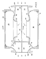
- a centrifugal blower 10 comprising a stationary housing 12 which is open at both axial or longitudinal ends 14 and 16 thereof (FIGURE 2).
- End cap members 18 (FIGURES 2, 4 and 5) are provided for closing the respective open end of the stationary housing 12.
- Such end cap members 18 may be provided with conventional sealing means, such as O-rings 20, or packing, or the like, for sealing the juncture between each end cap member 18 and its respective open end of the housing 12 section, thus preventing the emission of gas between the junctures thereof.
- Threaded fastener means 21 may be provided for removably securing the end cap members 18 to the housing section 12 in fluid tight relation.
- a rotatable shaft member 22 extends axially or longitudinally of housing section 12, and into the spaced plenum chambers 24, 26 defined by the housing.
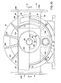
- Each of the end plates 18 in the embodiment illustrated includes an integral barrier wall 28 secured thereto by means of connecting hub section 29, with the barrier wall 28 being circular on its outer periphery, as can be seen in FIGURE 4.
- Barrier wall 28 in the embodiment illustrated, comprises a generally radially extending inner portion 30 and a generally obliquely extending outer portion 30a attached to the inner portion and sloping inwardly therefrom, and defining in conjunction with the inner portion a relatively shallow recess 32 (FIGURE 5) which is adapted to receive therein in coacting but rotatable relationship the associated impeller member 34 or 34a (FIGURE 2) associated with the respective plenum chamber.
- each end cap mounts its respective barrier wall in proper position in the plenum chamber for coaction with its associated impeller.
- each impeller 34 or 34a comprises a backing plate 38 of circular peripheral.configuration (FIGURES 6 and 7) formed integrally in the embodiment illustrated, with hub portion 40, with the backing plate 38 comprising a generally radially extending section 42 and an outer diagonally inwardly extending section 42a formed generally complementary to the corresponding configuration of the aforementioned sections 30, 30a of barrier wall 28 attached to the respective end cap 18.
- section 42a is disposed at an angle X or approximately 22á1 ⁇ 2° with respect to the plane of the face of the radially extending portion 42 and likewise for the corresponding portions of the respective barrier wall.
- the clearance between the impeller and the respective barrier wall is preferably in the order of approximately 12 to 15 thousands of an inch (.0012-.0015) and thus it will be seen that the latter are disposed close to one another, with the impeller also being disposed close to the inner surface configuration 43 of the respective plenum chamber defined by the housing 12 as best seen in FIGURE 2. It is preferable in order to hold the tolerances between the impeller and the barrier wall and the confronting housing surfaces that the shaft and impellers be precisely balanced prior to assembly into the housing.
- the blades 44 of the impeller are of the backward directed type (FIGURE 6) and extend diagonal'ly and arcuately outwardly from the hub 40 (FIGURE 8) to point 46 thereon with the blades 44 being integrally attached to the inner side of the backup plate 38.
- the impeller illustrated in FIGURES 6-8 is the lefthand impeller (with respect to FIGURE 2) with the other or righthand impeller (illustrated in FIGURE 2) being a mirror image of the impeller shown in FIGURES 6-8.
- the impeller blades 44 as can be best seen in FIGURES 6 and 8 extend arcuately and radially outwardly from the respective point 46 thereon, and relative to the vertical plane of the inner face 50 of the hub 40 to outer location 54 thereon and then slope upwardly to a juncture with the outer end of oblique portion 42a of the backup plate 38. At the outer end of each blade 44, the latter is bent as at 56 in the direction of rotation of the impeller, as can be best seen in FIGURE 6 in order to aid in preventing centrifugal displacement noise. Impeller blades 44 define channels through which the gas flows after being taken into the blower, as will be hereinafter described in greater detail.
- each impeller 34, 34a is keyed to the power shaft 22 of the blower, and as indicated by reference number 64 in FIGURE 2.
- the shaft 22 includes a generally central shoulder portion 66 which is adapted to abut with-the aforementioned inner face 50 of the hub 40 of the respective impeller, and with there being provided a circular bushing 68, coacting with the outer side of the respective impeller in the circular recess 58 therein.
- Openings 70 are spaced uniform radial distances from the axial center of the respective impeller.
- Each bearing assembly 71 rotatably mounts the shaft and associated impellers with respect to the stationary housing, and in the embodiment illustrated comprises the aforementioned inner bearing cap 60 which has a cylindrical portion 72 circumscribing the aforementioned bushing 68, and received in the recess 58 on the respective impeller, and an outer bearing cap 76 or 76a which is adapted to be secured as by means of threaded fasteners 78 to the respective end cap member 18.
- Bearing cap member 76 has an enlarged opening 80 therein as can be best seen in FIGURES 2 and 10, through which extends the shaft 22, to exteriorly of the blower as shown in FIGURE 2. Opening 80 is preferably provided with spring seal member 82 disposed in a recess in the end cap member 76, as shown in FIGURE 2.
- the exterior end of shaft 22 is adapted for ready coupling to a prime mover P, for rotation of shaft 22 and mounted impellers 34, 34a.
- the outer bearing cap member 76a on the righthand end of the blower differs from that on the lefthand end in that the shaft 22 does not extend through the bearing cap 76a and therefore the latter does not embody any enlarged opening therein, but is provided with a smaller opening 84 which is preferably threaded and which has a removable threaded member 84a received in opening 84 'in substantially fluid tight condition.
- Shaft 22 is threaded on its exterior as at 86, 86a and is adapted to coact with an associated threaded lock nut 88, with there also being preferably provided a lock washer 89 for coaction with the lock nut 88, for positively locking or positioning the duplex roller bearing members 90 which provide for rotation of the shaft 22 and attached impellers 34, 34a with respect to the stationary housing and associated barrier walls 28.
- Spring seals 92 of conventional type may be provided coacting between the respective inner bearing cap 72 and bushing member 68.
- O-ring seals 93 may be provided as shown in FIGURE 2, between the outer bearing cap members 76, 76a and the hub of the respective end cap 18.
- bearing assemblies 71 If it becomes desirable or necessary to replace the bearing assemblies 71 in the blower, this can be accomplished without disassembling the entire blower.
- the outer bearing cap members 76 or 76a of bearing assemblies 71 can be removed by the removal of the associated threaded fasteners 78, and then the lock nut and associated lock washer 88, 89 can be backed off the respective end of the shaft, thus clearing the way for outward axial movement of the bearing members 90.
- a suitable conventional "puller” or like mechanism (not shown but similar to a gear puller) can be utilized using the respective end of the shaft as the bearing point, and inserting elongated threaded bolts through openings 94 (FIGURE 2) extending through the respective end plate 18 and associated barrier wall portion 28, and threading such threaded bolt members into the aforementioned threaded openings 70 in the respective impeller.
- the threaded fasteners 21 can be removed from the end plate 18 so that the latter and attached barrier wall 28 is no longer secured to the respective end of the blower housing 12.
- the "puller” can be actuated using confronting end of the shaft as the bearing point for the conventional threaded actuator of the "puller”, to pull the attached impeller, the bearing assembly, and the integral end plate and barrier wall completely off the shaft 22 and out of the associated end of the housing, thus enabling expeditious replacement or repair of the bearing assembly.
- the new or repaired bearing assembly 71 can then be assembled with the end plate and barrier wall, and the impeller, and then moved axially inwardly of the shaft and into the housing to reassemble the impeller, the bearing assembly, and the end plate and barrier wall on the shaft, with the key 64 being received within the key slot 96 in the impeller to again fix the latter to the shaft.
- the fasteners 21 can be reinstalled to secure the end plate to the housing, and the lock washer and lock nut 88, 89 can then be replaced on the end of the shaft, and the outer bearing cap 76, 76a fastened back, by means of its associated fasteners 78, to the respective end plate.
- a gas inlet 104 is provided for entering or intaking gas into the blower, and an inline gas outlet 106 is disposed on the other side of the blower housing crosswise of the shaft 22, for exiting pressurized gas from the blower.
- Transversely extending (with respect to the longitudinal axis of the blower) wall 108 divides the inlet 104 and the outlet 106 into two completely separate sections, so that the entering gas flows in generally equal amounts in the directions of the full line arrows shown in FIGURE 3, to the lefthand and to the righthand impellers of the blower, and exits in generally equal amounts from the lefthand and righthand plenum chambers of the blower out the outlet 106, and to avoid internal turbulence which if permitted to occur would create additional heat.
- Wall 108 has an opening 110 therethrough, through which extends the drive shaft 22 of the blower.
- Transverse wall 111 (FIGURE 3) closes the ends of the inlet sections 115 of the blower housing.
- an outlet opening 112 is provided from each of the plenum chambers 24, 26, which open into the respective exit section 114 of the blower housing. Openings 112, as can be best seen in FIGURE 1 and FIGURE 9 are preferably vertically elongated, and communicate the respective plenum chamber with the respective exit section 114 of the blower housing.
- the exterior of housing 12 at inlet sections 115 of the blower is of generally cylindrically configuration as can be best seen in FIGURE 2, while the exit sections 114 are defined by walls of more box-like configuration, and comprising upper and lower generally planar wall sections 118, 119, as best seen in FIGURE 9.
- the gas outlet opening 119a (FIGURE 9) is preferably of circular configuration and of the same size opening as the circular opening at the blower inlet 104.
- Aforementioned wall sections 118, 119 merge smoothly with opening 119a, as do the defining side wall portions of exit sections 114 (FIGURE 3).
- the inlet 104 to the blower and the outlet 106 from the blower are inline with one another crosswise of shaft 22; with such arrangement and the opposed balanced impellers, substantially zero thrust is applied to the bearing structure during operation of the blower.
- the gas is taken into the respective inlet section 115, flows through the eye of the respective impeller and through shroud portion 120 of the housing coacting with the respective impeller, and then into the associated plenum chamber, and thence into the respective exit section 114.
- Each end plate 18 is preferably provided with a threaded opening 121 therein which in adapted to receive in coacting threaded relationship, a pressure relief valve of conventional type, for providing pressure relief to the respective plenum chamber of the blower.
- a pressure relief valve of conventional type, for providing pressure relief to the respective plenum chamber of the blower.
- Such relief valve mechanism (many of which are known in the art) is commercially available and may be purchased, for instance, from Fisher Controls Company of Cleveland, Ohio. Such valve mechanism may be set, for instance, to open and relieve the pressure in the respective plenum chamber, at approximately 20 psig.
- cooling and strengthening ribs 122 extending outwardly from the body 124 of the blower and intermediate plenum chambers 24, 26, are preferably provided, with such cooling ribs merging as can be seen in FIGURES 2 and 9 with the exterior of the respective plenum chamber.
- the end cap members 18 are each preferably provided with exterior vertically extending ribs 126 which aid in removal of the heat from the blower as well as aiding in strengthening the defining wall of the end cap member.
- the blower illustrated is adapted to receive the gas at for instance a minimum pressure at the inlet 104 and to discharge it at the outlet 106 at a pressure of, for instance, 3 to 5 pounds per square inch gage, and of a quantity, for instance, of approximately 3400 cubic feet per minute.
- the shaft may be rotating at between 3000 to 10,000 R.P.M. to achieve various displacement pressure and vacuum.
- the blower possesses a low noise level during operatio thereof, and may be expeditiously formed of aluminum alloy castings so that it can provide a relatively lig] weight blower mechanism that is fairly readily portable
- the bearing assemblies 71 may be maintained in lubricated condition by conventional lubricant disposed behind the respective outer bearing cap 76, 76a.
- the invention provides a novel centrifugal blower comprising a housing defining a pair of axially spaced plenum chambers with an impeller disposed in each of said chambers for rotation with respect thereto, and with a shaft extending axially of the housing and mounting the opposed impellers thereon, and with a gas inlet into and a gas outlet from each of the chambers,- with the gas inlet and gas outlet being disposed in aligned relationship crosswise of the shaft, whereby minimum thrust forces are applied to the shaft and the associated bearings during operation thereof.
- the invention also provides a novel relatively lightweight blower mechanism adapted for instance to move gas through a line system at a relatively high flow rate, and wherein means are provided for expeditiously replacing the bearing structure of the blower without the necessity of disassembling the entire blower.
Landscapes
- Engineering & Computer Science (AREA)
- Mechanical Engineering (AREA)
- General Engineering & Computer Science (AREA)
- Structures Of Non-Positive Displacement Pumps (AREA)
- Control Of Non-Positive-Displacement Pumps (AREA)
Applications Claiming Priority (2)
| Application Number | Priority Date | Filing Date | Title |
|---|---|---|---|
| US68964285A | 1985-01-08 | 1985-01-08 | |
| US689642 | 1985-01-08 |
Publications (2)
| Publication Number | Publication Date |
|---|---|
| EP0187645A2 true EP0187645A2 (fr) | 1986-07-16 |
| EP0187645A3 EP0187645A3 (fr) | 1988-06-15 |
Family
ID=24769333
Family Applications (1)
| Application Number | Title | Priority Date | Filing Date |
|---|---|---|---|
| EP86100069A Withdrawn EP0187645A3 (fr) | 1985-01-08 | 1986-01-03 | Ventilateur centrifuge opposé sur une ligne et équilibré |
Country Status (3)
| Country | Link |
|---|---|
| EP (1) | EP0187645A3 (fr) |
| JP (1) | JPS61205394A (fr) |
| IL (1) | IL77481A (fr) |
Cited By (1)
| Publication number | Priority date | Publication date | Assignee | Title |
|---|---|---|---|---|
| CN108131309A (zh) * | 2018-02-10 | 2018-06-08 | 江苏星宇户外休闲用品有限公司 | 一种双向电动充气泵 |
Families Citing this family (1)
| Publication number | Priority date | Publication date | Assignee | Title |
|---|---|---|---|---|
| JP6532271B2 (ja) * | 2015-04-20 | 2019-06-19 | 株式会社マキタ | 背負式送風作業機 |
Family Cites Families (3)
| Publication number | Priority date | Publication date | Assignee | Title |
|---|---|---|---|---|
| GB191403626A (en) * | 1914-02-12 | 1914-10-15 | Percy William Allday | Improvements in Centrifugal Fans. |
| GB191508156A (en) * | 1914-06-06 | 1916-06-02 | Oerlikon Maschf | Multiple Stage Blower. |
| GB854127A (en) * | 1957-06-28 | 1960-11-16 | Power Jets Res & Dev Ltd | Improvements in or relating to radial-flow compressors and turbines |
-
1985
- 1985-12-29 IL IL77481A patent/IL77481A/xx unknown
-
1986
- 1986-01-03 EP EP86100069A patent/EP0187645A3/fr not_active Withdrawn
- 1986-01-08 JP JP61000824A patent/JPS61205394A/ja active Pending
Cited By (1)
| Publication number | Priority date | Publication date | Assignee | Title |
|---|---|---|---|---|
| CN108131309A (zh) * | 2018-02-10 | 2018-06-08 | 江苏星宇户外休闲用品有限公司 | 一种双向电动充气泵 |
Also Published As
| Publication number | Publication date |
|---|---|
| JPS61205394A (ja) | 1986-09-11 |
| EP0187645A3 (fr) | 1988-06-15 |
| IL77481A (en) | 1991-06-30 |
Similar Documents
| Publication | Publication Date | Title |
|---|---|---|
| US5009578A (en) | Motor driven pumps | |
| AU615256B2 (en) | Centrifugal pump bearing arrangement | |
| EP0726397B1 (fr) | Pompe avec passage d'écoulement amélioré | |
| US3953150A (en) | Impeller apparatus | |
| US3861825A (en) | Multistage pump and manufacturing method | |
| CA1235950A (fr) | Montage de garniture mecanique pour pompe a boue | |
| US3817653A (en) | Centrifugal pump apparatus | |
| EP0552940A1 (fr) | Pompes à anneau liquide avec parois circonférentielles rotatives | |
| US3963371A (en) | Multi-stage pump | |
| US5873697A (en) | Method of improving centrifugal pump efficiency | |
| US20020192088A1 (en) | Centrifugal pump with multiple inlets | |
| US6551058B2 (en) | Rotatory pump having a knobbed impeller wheel, and a knobbed impeller wheel therefor | |
| US3778181A (en) | Centrifugal pump | |
| US3499388A (en) | Centrifugal pump | |
| US4929149A (en) | Gas blower | |
| US20110286840A1 (en) | Liquid ring pump with liner | |
| US2970750A (en) | Centrifugal gas compression | |
| GB2044853A (en) | Axial flow slurry pump | |
| US20060062666A1 (en) | Variable area diffuser | |
| JP2011080484A (ja) | 多段タービンインペラ型ポンプ集成体 | |
| EP0105140A2 (fr) | Garniture étanche pour arbres | |
| JPS6340950B2 (fr) | ||
| US4496281A (en) | Centrifugal pump | |
| EP0187645A2 (fr) | Ventilateur centrifuge opposé sur une ligne et équilibré | |
| US3044684A (en) | Centrifugal compressor construction |
Legal Events
| Date | Code | Title | Description |
|---|---|---|---|
| PUAI | Public reference made under article 153(3) epc to a published international application that has entered the european phase |
Free format text: ORIGINAL CODE: 0009012 |
|
| AK | Designated contracting states |
Kind code of ref document: A2 Designated state(s): AT BE CH DE FR GB IT LI LU NL SE |
|
| PUAL | Search report despatched |
Free format text: ORIGINAL CODE: 0009013 |
|
| AK | Designated contracting states |
Kind code of ref document: A3 Designated state(s): AT BE CH DE FR GB IT LI LU NL SE |
|
| 17P | Request for examination filed |
Effective date: 19881208 |
|
| 17Q | First examination report despatched |
Effective date: 19900326 |
|
| STAA | Information on the status of an ep patent application or granted ep patent |
Free format text: STATUS: THE APPLICATION IS DEEMED TO BE WITHDRAWN |
|
| 18D | Application deemed to be withdrawn |
Effective date: 19910902 |