EP0187685A2 - Einrichtung zum Aufwickeln eines Rolladens und Rolladen versehen mit dieser Einrichtung - Google Patents
Einrichtung zum Aufwickeln eines Rolladens und Rolladen versehen mit dieser Einrichtung Download PDFInfo
- Publication number
- EP0187685A2 EP0187685A2 EP86200002A EP86200002A EP0187685A2 EP 0187685 A2 EP0187685 A2 EP 0187685A2 EP 86200002 A EP86200002 A EP 86200002A EP 86200002 A EP86200002 A EP 86200002A EP 0187685 A2 EP0187685 A2 EP 0187685A2
- Authority
- EP
- European Patent Office
- Prior art keywords
- bar
- drum
- winding mechanism
- mechanism according
- supports
- Prior art date
- Legal status (The legal status is an assumption and is not a legal conclusion. Google has not performed a legal analysis and makes no representation as to the accuracy of the status listed.)
- Withdrawn
Links
Images

Classifications
-
- E—FIXED CONSTRUCTIONS
- E06—DOORS, WINDOWS, SHUTTERS, OR ROLLER BLINDS IN GENERAL; LADDERS
- E06B—FIXED OR MOVABLE CLOSURES FOR OPENINGS IN BUILDINGS, VEHICLES, FENCES OR LIKE ENCLOSURES IN GENERAL, e.g. DOORS, WINDOWS, BLINDS, GATES
- E06B9/00—Screening or protective devices for wall or similar openings, with or without operating or securing mechanisms; Closures of similar construction
- E06B9/02—Shutters, movable grilles, or other safety closing devices, e.g. against burglary
- E06B9/08—Roll-type closures
- E06B9/11—Roller shutters
- E06B9/17—Parts or details of roller shutters, e.g. suspension devices, shutter boxes, wicket doors, ventilation openings
- E06B9/171—Rollers therefor; Fastening roller shutters to rollers
-
- E—FIXED CONSTRUCTIONS
- E06—DOORS, WINDOWS, SHUTTERS, OR ROLLER BLINDS IN GENERAL; LADDERS
- E06B—FIXED OR MOVABLE CLOSURES FOR OPENINGS IN BUILDINGS, VEHICLES, FENCES OR LIKE ENCLOSURES IN GENERAL, e.g. DOORS, WINDOWS, BLINDS, GATES
- E06B9/00—Screening or protective devices for wall or similar openings, with or without operating or securing mechanisms; Closures of similar construction
- E06B9/02—Shutters, movable grilles, or other safety closing devices, e.g. against burglary
- E06B9/08—Roll-type closures
- E06B9/11—Roller shutters
- E06B9/17—Parts or details of roller shutters, e.g. suspension devices, shutter boxes, wicket doors, ventilation openings
- E06B9/174—Bearings specially adapted therefor
-
- E—FIXED CONSTRUCTIONS
- E06—DOORS, WINDOWS, SHUTTERS, OR ROLLER BLINDS IN GENERAL; LADDERS
- E06B—FIXED OR MOVABLE CLOSURES FOR OPENINGS IN BUILDINGS, VEHICLES, FENCES OR LIKE ENCLOSURES IN GENERAL, e.g. DOORS, WINDOWS, BLINDS, GATES
- E06B9/00—Screening or protective devices for wall or similar openings, with or without operating or securing mechanisms; Closures of similar construction
- E06B9/56—Operating, guiding or securing devices or arrangements for roll-type closures; Spring drums; Tape drums; Counterweighting arrangements therefor
- E06B9/60—Spring drums operated only by closure members
Definitions
- the present invention relates to a winding mechanism for a mechanical shutter, with at least one drum and one spiral spring, the internal end of which can be immobilized relative to a bar on which the drum is mounted, and the external end of which is fixed relative to the drum, means being provided for clamping the spring in the drum.
- the main object of the invention is to offer a winding mechanism of the type defined above, a mechanism which allows very simple assembly and above all which allows repair or replacement of certain important elements.
- the drum is rotatably mounted on a length of tube on which the internal end of the spiral spring is fixed, and which is slidably removable on the aforementioned bar and can be immobilized against rotation on this bar, the aforementioned bar being in turn rotary and capable of being made stationary with respect to supports which cannot rotate around the bar.
- the bar has a polygonal external cross section, more particularly square.
- the supports are provided at least at the ends of the aforementioned bar and they have cylindrical projections co-axial with the latter, projections on which these ends are slid, adjustable means allowing s oppose the rotation of the bar on these projections.
- the invention also relates to a mechanical shutter which is equipped with at least one such winding mechanism, and to a method for installing a mechanical shutter equipped with a winding mechanism.
- This process is characterized in that at least one length of tube is slid with a drum and a spiral spring mounted on it, on the bar and it is immobilized against a rotation around its axis on this bar, in that the upper edge of the shutter is fixed in the wound state on the drum, in that the rotary bar is arranged on the supports, in that the spring is tightened inside the drum by rotating the bar around its axis relative to the supports, and in that finally the bar is blocked against rotation relative to the supports.
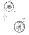
- the winding mechanism according to the invention consists of at least one drum 1 and a spiral spring 2, the internal end 3 of which can be immobilized relative to a bar 4 on which the drum 1 is mounted, and the external end of which 5 is fixed relative to the drum 1.
- this drum 1 is mounted at rotation over a length of tube 6 which is slid over the bar 4 and can be blocked against rotation on the latter.
- the internal end 3 of the spiral spring 2, which is integral with the bar 4, is fixed to the length of tube 6, for example by means of a screw 7, as illustrated in the figures.
- the bar 4 is rotated in turn relative to two supports 8, which cooperate with its two ends.
- This bar can be blocked against rotation on these supports, for example by means of one or more screws 9.
- the bar 4 preferably has a polygonal and preferably square cross section, as shown in the figures, so that it can be blocked against rotation in a very simple and effective manner.
- the length of tube 6 preferably has a cylindrical outer surface, while the cross section of the inner surface can be arbitrary and for example also polygonal.
- the drum 1 is preferably formed by two parallel discs 12 and 13, which can rotate along the length of tube 6 and between which is mounted the spiral spring 2, and by a protective plate 14, bent in cylindrical form, which is fixed on the edges of the discs 12 and 13 and which covers the spiral spring 2.
- these are for example folded outwards.
- the supports 8 which are provided at the ends of the bar 4, each have a cylindrical projection 17, co-axial with this bar, projections on which the bar which is hollow, can be slid by its ends.
- the supports 8 have an L-shaped component 18.
- the projection 17 is provided, while on the other branch 19 'which is on the same side of this projection, one can provide the screw 9 which can be tightened against the outer face of the bar 4 in a direction which is substantially perpendicular to that of its axis.
- the element 18 can be mounted on rollers 20, which are fixed on the external face of the branch 19 of this element and which are movable in a profile in U 21 which is fixedly mounted for example against the side wall of the shutter box not shown.
- Such a movable element 18 is however not absolutely necessary and in general this element will be fixed immobile in the shutter box.
- drum 1 can be mounted for rotation by means of ball bearings 22 along the length of tube 6.
- the spring 2 is tightened or bandaged in the drums 1 by rotating the bar 4 around its axis, for example by means of two keys not shown in order to avoid the elastic return of the spring.
- This tightening is stopped at the moment when the mechanical shutter begins to "live", that is to say that there is a certain movement in the part hanging freely down the shutter.
- the drums are fixed directly to a round bar, which cooperates with a ratchet wheel which is provided on the ends of the bar and which allows, by rotating the latter around its axis, to tighten or band the spring in the drums.
Landscapes
- Engineering & Computer Science (AREA)
- Structural Engineering (AREA)
- Architecture (AREA)
- Civil Engineering (AREA)
- Operating, Guiding And Securing Of Roll- Type Closing Members (AREA)
Applications Claiming Priority (2)
| Application Number | Priority Date | Filing Date | Title |
|---|---|---|---|
| BE214322 | 1985-01-11 | ||
| BE0/214322A BE901483A (nl) | 1985-01-11 | 1985-01-11 | Oprolmechanisme voor rolluik en rolluik uitgerust met dergelijk mechanisme. |
Publications (2)
| Publication Number | Publication Date |
|---|---|
| EP0187685A2 true EP0187685A2 (de) | 1986-07-16 |
| EP0187685A3 EP0187685A3 (de) | 1987-05-20 |
Family
ID=3843842
Family Applications (1)
| Application Number | Title | Priority Date | Filing Date |
|---|---|---|---|
| EP86200002A Withdrawn EP0187685A3 (de) | 1985-01-11 | 1986-01-03 | Einrichtung zum Aufwickeln eines Rolladens und Rolladen versehen mit dieser Einrichtung |
Country Status (1)
| Country | Link |
|---|---|
| EP (1) | EP0187685A3 (de) |
Cited By (7)
| Publication number | Priority date | Publication date | Assignee | Title |
|---|---|---|---|---|
| EP0446049A3 (en) * | 1990-03-07 | 1992-06-24 | Rotalac Plastics Limited | Improved roller shutter assembly |
| FR2691745A1 (fr) * | 1992-05-27 | 1993-12-03 | Wallet Pierre | Bobine à ressort et fermetures à enroulement comportant de telles bobines à ressort. |
| FR2712347A1 (fr) * | 1993-11-09 | 1995-05-19 | Fab Sa | Dispositif de compensation pour rideau roulant ou autre. |
| EP0768445A1 (de) * | 1995-10-09 | 1997-04-16 | Gérard Tournier | Aufrollbare Verschlusseinrichtung mit Festwelle und Federgewichtsausgleich |
| GB2313143A (en) * | 1996-05-13 | 1997-11-19 | Louver Lite Ltd | Roller blind mounting |
| ES2302429A1 (es) * | 2006-05-05 | 2008-07-01 | Alfa Santiga, S.L. | Soporte para el eje de una puerta enrollable y sistema de puerta enrollable. |
| IT202200012560A1 (it) * | 2022-06-14 | 2023-12-14 | De Luca Roberto | Dispositivo porta-molla per serrande avvolgibili |
Family Cites Families (4)
| Publication number | Priority date | Publication date | Assignee | Title |
|---|---|---|---|---|
| FR806812A (fr) * | 1936-04-23 | 1936-12-26 | Rouleau compensateur de fermetures s'enroulant | |
| DE734928C (de) * | 1940-05-22 | 1943-05-03 | Paul Schultes | Federrolle fuer Rollvorhaenge mit einer im Inneren befindlichen Aufwickelfeder |
| DE826251C (de) * | 1949-11-15 | 1951-12-27 | Wilhelm Stiegler | Federgehaeuse fuer die Rollachse von Rolladen |
| DE848613C (de) * | 1949-12-20 | 1952-09-04 | Oesterheld & Co | Von Hand bedienbares Rollenlager-Federgehaeuse fuer schwere Rollaeden, z. B. Garagen- oder Fabriktore u. dgl. |
-
1986
- 1986-01-03 EP EP86200002A patent/EP0187685A3/de not_active Withdrawn
Cited By (9)
| Publication number | Priority date | Publication date | Assignee | Title |
|---|---|---|---|---|
| EP0446049A3 (en) * | 1990-03-07 | 1992-06-24 | Rotalac Plastics Limited | Improved roller shutter assembly |
| US5351743A (en) * | 1990-03-07 | 1994-10-04 | Rotalac Plastics Limited | Improved roller shutter assembly |
| FR2691745A1 (fr) * | 1992-05-27 | 1993-12-03 | Wallet Pierre | Bobine à ressort et fermetures à enroulement comportant de telles bobines à ressort. |
| FR2712347A1 (fr) * | 1993-11-09 | 1995-05-19 | Fab Sa | Dispositif de compensation pour rideau roulant ou autre. |
| EP0768445A1 (de) * | 1995-10-09 | 1997-04-16 | Gérard Tournier | Aufrollbare Verschlusseinrichtung mit Festwelle und Federgewichtsausgleich |
| GB2313143A (en) * | 1996-05-13 | 1997-11-19 | Louver Lite Ltd | Roller blind mounting |
| ES2302429A1 (es) * | 2006-05-05 | 2008-07-01 | Alfa Santiga, S.L. | Soporte para el eje de una puerta enrollable y sistema de puerta enrollable. |
| ES2302429B1 (es) * | 2006-05-05 | 2009-05-05 | Alfa Santiga, S.L. | Soporte para el eje de una puerta enrollable y sistema de puerta enrollable. |
| IT202200012560A1 (it) * | 2022-06-14 | 2023-12-14 | De Luca Roberto | Dispositivo porta-molla per serrande avvolgibili |
Also Published As
| Publication number | Publication date |
|---|---|
| EP0187685A3 (de) | 1987-05-20 |
Similar Documents
| Publication | Publication Date | Title |
|---|---|---|
| EP0479719B1 (de) | Aufrolleinrichtung mit rohrförmigem Motor für Stores, Jalousien oder dergleichen | |
| BE1004897A3 (fr) | Dispositif de fermeture, de separation ou de couverture. | |
| FR2578299A1 (fr) | Dispositif de blocage d'une tige pour empecher tous mouvements d'extension et de contraction de celle-ci | |
| FR2560922A1 (fr) | Dispositif pour empecher l'application d'une tension excessive au moteur a ressort d'un store de fenetre | |
| EP1956177A1 (de) | Vorrichtung mit flexiblem Vorhang | |
| EP0187685A2 (de) | Einrichtung zum Aufwickeln eines Rolladens und Rolladen versehen mit dieser Einrichtung | |
| FR2682713A1 (fr) | Dispositif de reglage angulaire pour bras articule de store a rouleau ou similaire. | |
| EP0564375A1 (de) | Bewegliche Vorrichtung zum Halten von Profilen mit einem Abstand von einem Substrat wie eine Mauer | |
| FR2684461A1 (fr) | Boite de filtres utilisable sur des cameras de cinema professionnelles ou des cameras video. | |
| WO2012143519A1 (fr) | Dispositif de suspension d'une toile | |
| FR2724194A3 (fr) | Store a caisson | |
| EP0010016B1 (de) | Antriebsmechanismus zur Parallelführung einer Reissschiene auf einem Zeichenbrett | |
| WO2008025810A1 (fr) | Dispositif pour annuler la torsion d'un lien entre une extremite fixe et une extremite tournante | |
| FR2532611A1 (fr) | Dispositif d'amarrage d'une planche a voile, ou analogue | |
| FR2619850A1 (fr) | Volet roulant pour porte, fenetre ou analogue | |
| FR2520817A1 (fr) | Pince d'assemblage de profiles | |
| EP0531274A1 (de) | Befestigungsvorrichtung für ein Tuch auf einem Wickelträger | |
| BE1017124A6 (fr) | Dispositif a rideau flexible. | |
| EP0096137A1 (de) | Aufwickelvorrichtung in Gehäuse | |
| FR2519246A1 (fr) | Dispositif pour la presentation d'articles, tels que des pots de fleurs | |
| FR2716922A1 (fr) | Structure de protection. | |
| WO1997010398A1 (fr) | Support de store a banne | |
| FR2746063A1 (fr) | Dispositif permettant de faciliter le deplacement d'un siege de vehicule automobile vers l'avant de celui-ci | |
| BE1011541A6 (fr) | Agencement d'ecran du type a ecran susceptible d'etre etendu entre deux montants. | |
| FR2529816A1 (fr) | Tendeur pour fil metallique |
Legal Events
| Date | Code | Title | Description |
|---|---|---|---|
| PUAI | Public reference made under article 153(3) epc to a published international application that has entered the european phase |
Free format text: ORIGINAL CODE: 0009012 |
|
| AK | Designated contracting states |
Kind code of ref document: A2 Designated state(s): AT CH DE FR GB IT LI LU NL SE |
|
| PUAL | Search report despatched |
Free format text: ORIGINAL CODE: 0009013 |
|
| AK | Designated contracting states |
Kind code of ref document: A3 Designated state(s): AT CH DE FR GB IT LI LU NL SE |
|
| STAA | Information on the status of an ep patent application or granted ep patent |
Free format text: STATUS: THE APPLICATION IS DEEMED TO BE WITHDRAWN |
|
| 18D | Application deemed to be withdrawn |
Effective date: 19871121 |