EP0187740B1 - Einphasiger motor mit einem magnetisierten läufer - Google Patents
Einphasiger motor mit einem magnetisierten läufer Download PDFInfo
- Publication number
- EP0187740B1 EP0187740B1 EP84902696A EP84902696A EP0187740B1 EP 0187740 B1 EP0187740 B1 EP 0187740B1 EP 84902696 A EP84902696 A EP 84902696A EP 84902696 A EP84902696 A EP 84902696A EP 0187740 B1 EP0187740 B1 EP 0187740B1
- Authority
- EP
- European Patent Office
- Prior art keywords
- rotor
- pole
- pole pieces
- stator
- peripheral
- Prior art date
- Legal status (The legal status is an assumption and is not a legal conclusion. Google has not performed a legal analysis and makes no representation as to the accuracy of the status listed.)
- Expired
Links
Images


Classifications
-
- G—PHYSICS
- G04—HOROLOGY
- G04C—ELECTROMECHANICAL CLOCKS OR WATCHES
- G04C15/00—Clocks driven by synchronous motors
-
- G—PHYSICS
- G04—HOROLOGY
- G04C—ELECTROMECHANICAL CLOCKS OR WATCHES
- G04C13/00—Driving mechanisms for clocks by primary clocks
- G04C13/08—Secondary clocks actuated intermittently
- G04C13/10—Secondary clocks actuated intermittently by electromechanical step-advancing mechanisms
- G04C13/11—Secondary clocks actuated intermittently by electromechanical step-advancing mechanisms with rotating armature
-
- H—ELECTRICITY
- H02—GENERATION; CONVERSION OR DISTRIBUTION OF ELECTRIC POWER
- H02K—DYNAMO-ELECTRIC MACHINES
- H02K21/00—Synchronous motors having permanent magnets; Synchronous generators having permanent magnets
- H02K21/12—Synchronous motors having permanent magnets; Synchronous generators having permanent magnets with stationary armatures and rotating magnets
- H02K21/24—Synchronous motors having permanent magnets; Synchronous generators having permanent magnets with stationary armatures and rotating magnets with magnets axially facing the armatures, e.g. hub-type cycle dynamos
-
- H—ELECTRICITY
- H02—GENERATION; CONVERSION OR DISTRIBUTION OF ELECTRIC POWER
- H02K—DYNAMO-ELECTRIC MACHINES
- H02K37/00—Motors with rotor rotating step by step and without interrupter or commutator driven by the rotor, e.g. stepping motors
- H02K37/10—Motors with rotor rotating step by step and without interrupter or commutator driven by the rotor, e.g. stepping motors of permanent magnet type
- H02K37/12—Motors with rotor rotating step by step and without interrupter or commutator driven by the rotor, e.g. stepping motors of permanent magnet type with stationary armatures and rotating magnets
- H02K37/125—Magnet axially facing armature
Definitions
- This invention relates to the single-phase motor with magnetic rotor.
- magnetic rotor motors There are different types of magnetic rotor motors.
- motors of the same type there are also different motors of the same type as that according to the invention.
- the motor includes a rotor whose magnetization axes are parallel to the axis of rotation of the rotor as described for example in documents FR-A-2435 150 and FR-A-2 283 576
- existing motors of this type have defects in the design of their structure, which in particular penalize their performance. This will appear clearly below on the basis of the equivalent diagram of the engine according to the present invention.
- the object of the invention is to design an electric motor of optimum efficiency in a given space, using existing materials and which can be manufactured by industrial processes.
- Another object of the invention is the design of an engine whose range of powers can be very wide, without modification of the design of the engine.
- Another object of the present invention is the design of an engine whose number of steps per revolution can be very large, without modification of the design of the engine.
- the motor according to the invention has a yield of the order of 50%. The yield is even higher when the bulk is greater, the materials used are more efficient and the manufacturing tolerances are tighter.
- the power can typically be 100 uW for low powers and can be extended to much higher powers, without modification of the engine design.
- the field of application of the engine of the present invention is therefore very wide.
- medical instrumentation including systems that can be implemented in the human body, training systems for the aeronautics and space industry, office automation, robotics, photographic equipment, timepieces, etc.
- the motor according to the present invention operating in stepping mode is suitable for all systems using the digital technique, and more particularly for all those where the criteria of space, efficiency and power are determining.
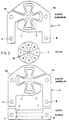
- This figure is a simplified exploded top view of the engine, which illustrates the structure of the engine.
- the rotor 1 is made of ferromagnetic material with a high coercive field and a low density, such as samarium-cobalt. It has N pairs of poles 1 p, whose magnetization axes are parallel to the axis of rotation la of the rotor and spaced by an equal angular interval. The magnetization direction of each of these axes is opposite to that of the adjacent axis.
- the rotor is placed between two stators, one, t lower, of index a, the other, upper, of index b.
- the pole pieces are made of ferromagnetic material with a low coercive field and high saturation induction.
- each stator The two pole pieces of each stator are coplanar and separated by a sinuous air gap 4.
- Each pole piece consists of N / 2 poles 5, spaced at an angular interval twice that existing between the adjacent magnetization axes of the rotor.
- the inner pole piece 2b of the upper stator b is magnetically connected to a first end A of a core 6, the second end B of which is magnetically connected to the inner pole piece 2a of the lower stator a, that is to say the pole piece of the lower stator, the poles of which are directly opposite.
- the other pole piece of the upper stator that is to say the outer pole piece 3b, is magnetically connected to the second end B of the core 6, the first end A of which is magnetically connected to the pole piece 3a of the lower stator. , that is to say the pole piece of the lower stator whose poles are directly opposite.
- the core 6 is made of ferromagnetic material with a low coercive field and a high saturation induction.
- a coil 7 is wound around the novau.
- the assembly is mounted, by way of example, as illustrated in FIG. 3 and described below.
- the lower stator is placed on a piece of non-ferromagnetic material 8.
- the pole pieces 2a, 2b, 3a and 3b are positioned by four screw feet 9.
- Two screw feet 9e also have a shoulder 10 on which the pole pieces are supported. of the upper stator.
- the screw feet may or may not be made of ferromagnetic material.
- Two spacers 11, made of soft ferromagnetic material, are interposed in the space between each of the ends of the core and each pole piece of the upper stator.
- the mounting device described above ensures, by the screw feet, the correct positioning in their planes of the pole pieces, and by the shoulders and spacers, the correct positioning in height of the pole pieces.
- the rotor is mounted as illustrated in FIG. 4.
- the rotor pivots in bearings 12 with low contact friction.
- the material used for the bearings is, for example, ruby.
- a pinion 13 is integral with the axis of rotation la of the rotor and makes it possible to transmit the rotational movement of the rotor to the entire gear train 14.
- the poles of the pole pieces can also be made asymmetrical with respect to the radial axes defining the angular interval between the poles.
- An example is given in FIG. 5. This design makes it possible, as we will see below, to create a phase shift between the positioning torque and the mutual torque, thus allowing the motor to start automatically.
- the pairs of poles 1 p of the rotor are directly opposite the poles 5 of the pole pieces of the stators, lower and upper.
- the motor therefore has an inversion of the flow of the rotor in the core over an angle of rotation of the rotor equal to 2n / N.
- the coil wound on the core When the coil wound on the core is supplied, it results, according to the laws of electromechanics, an interaction torque between the coil and the magnetized rotor, torque called below mutual mutual torque, of period 4n / N and whose equilibrium positions correspond to the rotor positions, for which the pairs of rotor poles are directly opposite the poles of the pole pieces of the stators.
- the permeance of the coil is limited by the sinuous air gap existing between the coplanar pole pieces of each stator.
- the motor In the absence of current, the motor exhibits a torque due to the magnetic rotor, a torque referred to below as positioning torque.
- positioning torque In the position of the rotor shown in FIG. 6, the permeance seen by the fluxes coming from the pairs of poles of the rotor is maximum. In this position, in accordance with the laws of electromechanics, the magnetic energy being negative, it is minimal and corresponds to a position of stable equilibrium.
- the motor therefore has a positioning torque of period 2n / N.
- the paces of the positioning pairs Ma and mutual Mab are given in FIG. 7a as a function of the angle of rotation u. rotor. To fix orders of magnitude, it is advantageous, from the point of view of efficiency, that the ratio between the positioning torque and the mutual torque is of the order of 0.25.
- the phase shift can be created there, for example, thanks to the asymmetry of the poles of the pole pieces.
- An exemplary embodiment is given in FIG. 5.
- the asymmetry of the poles of the pole pieces modifies the position of the rotor for which the permeance seen by the fluxes of the pairs of poles of the rotor is maximum, and, consequently, the position of stable equilibrium. This results in the announced angular offset between the mutual torque and the positioning torque, as shown in FIG. 7b, depending on the angle of rotation u. rotor.
- the poles of the pole pieces are dimensioned so that the positioning torque introduced by these poles is negligible with respect to the mutual torque. This can be done in particular by reducing the sinuous air gap between the coplanar pole pieces of the stators.
- the positioning torque, as well as the phase shift, are created by an auxiliary system so that the positioning torque has a period of 4n / N, that is to say the same period as that of the mutual torque.
- the way in which such an auxiliary system can be designed is known and is not explained.
- the paces of the positioning pairs Ma and mutual Mab are given for this second variant in FIG. 8a, similar to FIG. 7b.
- auxiliary system in the case of the bipolar stepper motor.
- the auxiliary system is then designed to give a positioning torque of 2n / N period.
- the motor described operating in stepping mode can also operate in continuous mode.
- the positioning torque is made negligible vis-à-vis the mutual torque.
- the flux of each pair of rotor poles is maximized by the fact that the flux collected by the poles of a pole piece of a stator closes by the directly opposite poles of the pole piece of the other stator, as already described. This is a second condition necessary for obtaining an optimum yield.
Landscapes
- Physics & Mathematics (AREA)
- General Physics & Mathematics (AREA)
- Engineering & Computer Science (AREA)
- Power Engineering (AREA)
- Iron Core Of Rotating Electric Machines (AREA)
- Permanent Magnet Type Synchronous Machine (AREA)
- Permanent Field Magnets Of Synchronous Machinery (AREA)
Claims (7)
dadurch gekennzeichnet, daß
jedes periphere Polstück (3a, 3b) zwischen zwei polaren Ausbuchtungen (5) eine Lücke aufweist, die diese untereinander verbindet, daß diese Lücken zweier peripherer Polstücke (3a, 3b) winkelmäßig gegeneinander versetzt angeordnet sind und dadurch, daß die Verbindungsstücke der zentralen Polstücke (2a, 2b) diese Lücken durchqueren.
dadurch gekennzeichnet, daß
die Lücken zweier peripherer Polstücke (3a, 3b) diametral gegenüberliegen.
dadurch gekennzeichnet, daß
jeder Verbindungsabschnitt aus demselben Stück hergestellt wird, aus dem das entsprechende Polstück (2a, 2b; 3a, 3b) hergestellt wird.
dadurch gekennzeichnet, daß
die Verbindungsbereiche der peripheren Polstücke (3a, 3b) Teile von diesen trennen, die ihren zugehörigen Lücken diametral gegenüberstehen und dadurch, daß die Verbindungsbereiche der zentralen Polstücke (2a, 2b) Enden der polaren Ausbuchtungen (5) abtrennen, die gegenüber diesen Lücken liegen.
dadurch gekennzeichnet, daß
die 4 Polstücke (2a, 2b; 3a, 3b) und ihre Verbindungsbereiche voneinander getrennt sind, daß die beiden peripheren Polstücke (3a, 3b) und ihre jeweiligen Verbindungsstücke dünn sind und beim Drehen eines Stücks um 180° aus einer Ebene die gleiche Form aufweisen und dadurch, daß die beiden zentralen Polstücke (2a, 2b) und ihre jeweiligen Verbindungstücke, wenn eines um 180° aus seiner Ebene herausgedreht wird, genau die gleiche Form und die gleiche Dicke habe wie die beiden peripheren Polstücke (3a, 3b) und wie deren zugehörige Verbindungsstücke.
dadurch gekennzeichnet, daß
die Spule (7) und ihr Kern (6) auf der Seite des Rotors (1) und des Stators (2, 3) angeordnet sind und dadurch, daß ihre Längsachse denselben Abstand von den Endflächen des Stators (1) aufweist.
dadurch gekennzeichnet, daß
ein Teil der polaren Ausbuchtungen (5) jeweils eine Asymmetrie im Verhältnis zur Mittelebene, die durch die Achse des Rotos (1) verläuft, aufweist.
Applications Claiming Priority (1)
| Application Number | Priority Date | Filing Date | Title |
|---|---|---|---|
| PCT/CH1984/000112 WO1986000765A1 (fr) | 1984-07-11 | 1984-07-11 | Moteur monophase a rotor aimante |
Publications (2)
| Publication Number | Publication Date |
|---|---|
| EP0187740A1 EP0187740A1 (de) | 1986-07-23 |
| EP0187740B1 true EP0187740B1 (de) | 1988-06-29 |
Family
ID=4541137
Family Applications (1)
| Application Number | Title | Priority Date | Filing Date |
|---|---|---|---|
| EP84902696A Expired EP0187740B1 (de) | 1984-07-11 | 1984-07-11 | Einphasiger motor mit einem magnetisierten läufer |
Country Status (5)
| Country | Link |
|---|---|
| US (1) | US4713565A (de) |
| EP (1) | EP0187740B1 (de) |
| JP (1) | JPS61502721A (de) |
| DE (2) | DE187740T1 (de) |
| WO (1) | WO1986000765A1 (de) |
Families Citing this family (6)
| Publication number | Priority date | Publication date | Assignee | Title |
|---|---|---|---|---|
| CH673199B5 (de) | 1988-08-25 | 1990-08-31 | Matthias Scholer | |
| FR2648632B1 (fr) * | 1989-06-16 | 1991-10-04 | Moving Magnet Tech | Actionneur electromagnetique monophase de faible encombrement |
| EP0452252A1 (de) * | 1990-04-11 | 1991-10-16 | Silcon Enterprises Ltd. | Schrittmotor für Zeitgeräte |
| FR2734962B1 (fr) * | 1995-05-29 | 1997-08-01 | Ebauchesfabrik Eta Ag | Moteur birotor multipolaire |
| AUPP696198A0 (en) * | 1998-11-06 | 1998-12-03 | Brits, Ludwig | A rotary electrical converter and controller therefor |
| CN1223068C (zh) | 1999-02-05 | 2005-10-12 | 精工爱普生株式会社 | 磁路结构、使用磁路结构的发电装置、电机和电子计时器 |
Family Cites Families (11)
| Publication number | Priority date | Publication date | Assignee | Title |
|---|---|---|---|---|
| FR1238445A (fr) * | 1959-07-03 | 1960-08-12 | Lepaute Henry S Ets | Moteur électrique autodémarreur à aimants permanents |
| CH558043A (de) * | 1972-08-30 | 1975-01-15 | ||
| FR2209246B1 (de) * | 1972-12-05 | 1978-03-03 | Fresard Freres Sa | |
| CH613359GA3 (en) * | 1974-08-28 | 1979-09-28 | Pulsed motor for horometrical apparatus | |
| GB1531314A (en) * | 1975-07-15 | 1978-11-08 | Seiko Instr & Electronics | Motor |
| GB1586056A (en) * | 1976-08-17 | 1981-03-18 | Ricoh Watch | Pulse motors |
| GB1537048A (en) * | 1976-09-23 | 1978-12-29 | United Gas Industries Ltd | Synchronous motors |
| DE2705685A1 (de) * | 1977-02-11 | 1978-08-17 | Quarz Zeit Ag | Einphasenschrittmotor |
| US4207483A (en) * | 1978-09-01 | 1980-06-10 | Warner Electric Brake & Clutch Co. | Step motor with circumferential stators on opposite sides of disc-like rotor |
| DE2938771A1 (de) * | 1979-09-25 | 1981-04-02 | Siemens AG, 1000 Berlin und 8000 München | Elektrisch-mechanischer wandler |
| JPS60501934A (ja) * | 1983-07-28 | 1985-11-07 | グロジヤン、ミシエル | 周辺にn/2対の極を有する磁化ロ−タによる多相モ−タ |
-
1984
- 1984-07-11 DE DE198484902696T patent/DE187740T1/de active Pending
- 1984-07-11 JP JP59502727A patent/JPS61502721A/ja active Pending
- 1984-07-11 DE DE8484902696T patent/DE3472512D1/de not_active Expired
- 1984-07-11 WO PCT/CH1984/000112 patent/WO1986000765A1/fr not_active Ceased
- 1984-07-11 EP EP84902696A patent/EP0187740B1/de not_active Expired
- 1984-07-11 US US06/855,305 patent/US4713565A/en not_active Expired - Lifetime
Also Published As
| Publication number | Publication date |
|---|---|
| DE187740T1 (de) | 1986-11-06 |
| US4713565A (en) | 1987-12-15 |
| JPS61502721A (ja) | 1986-11-20 |
| WO1986000765A1 (fr) | 1986-01-30 |
| DE3472512D1 (en) | 1988-08-04 |
| EP0187740A1 (de) | 1986-07-23 |
Similar Documents
| Publication | Publication Date | Title |
|---|---|---|
| EP0151159A1 (de) | Mehrphasiger motor mit einem magnetizierten, pro fläche n/2 polpaare aufweisenden läufer | |
| EP0151158B1 (de) | Mehrphasiger motor mit einem magnetisierten, n polpaare mit achsialer magnetisierung aufweisenden läufer | |
| EP0153930A1 (de) | Mehrphasiger motor mit einem magnetisierten, an seinem umfang n/2 polpaare, aufweisenden läufer | |
| EP0889576B1 (de) | Linearmotor | |
| EP2686940B1 (de) | Elektromotor und verwendung eines solchen motors bei einer schliess- oder sonnenschutzeinrichtung eines fensters | |
| FR2754953A1 (fr) | Moteur polyphase, notamment pour l'entrainement d'une aiguille d'un afficheur | |
| FR2688105A1 (fr) | Actionneur rotatif electromagnetique monophase de course entre 60 et 120 degres. | |
| FR2648636A1 (fr) | Moteur a courant continu biphase sans balais | |
| EP0811269A1 (de) | Zweiphasenmotor,insbesondere für zeitmessgerät oder zum antrieb eines zeigers einer anzeige | |
| EP0187740B1 (de) | Einphasiger motor mit einem magnetisierten läufer | |
| EP2201662A1 (de) | Elektromotor zum betreiben eines blendenelements oder eines sonnenschutzelements in einem gebäude | |
| FR2591400A1 (fr) | Moteur electrique synchrone di -ou tetraphase a un etage | |
| EP3970260A1 (de) | Geräuscharmer getriebemotor mit dissymetrischem elektromotor | |
| FR2645687A1 (fr) | Moteur electrique a commande magnetique sans collecteur | |
| EP1183770B1 (de) | Schrittmotor mit doppelspule in einer ebene | |
| EP0736696A1 (de) | Miniaturmagnetlager mit wenigstens einer aktiven Achse | |
| FR2918814A1 (fr) | Moteur pas-a-pas de construction simple et a faible cout | |
| WO1989012346A1 (fr) | Moteur electrique synchrone di- ou polyphase a rotor en forme de disque | |
| EP0149647A1 (de) | Einphasiger motor mit einem magnetisierten, pro fläche n/2 poolpaare aufweisenden, läufer | |
| EP0356396B1 (de) | Vielpoliger Schrittmotor | |
| EP4356498A1 (de) | Kleinmotor | |
| FR3004296A1 (fr) | Moteur electrique a faible couple de court-circuit, dispositif de motorisation a plusieurs moteurs et procede de fabrication d`un tel moteur | |
| EP0267845B1 (de) | Elektromagnetischer Stellantrieb mit zwei Luftspalten | |
| EP0718960B1 (de) | Mehrphasiger vielpoliger Schnittmotor | |
| FR2716046A1 (fr) | Machine électrique tournante à bobinage global. |
Legal Events
| Date | Code | Title | Description |
|---|---|---|---|
| PUAI | Public reference made under article 153(3) epc to a published international application that has entered the european phase |
Free format text: ORIGINAL CODE: 0009012 |
|
| AK | Designated contracting states |
Kind code of ref document: A1 Designated state(s): AT BE CH DE FR GB LI LU NL SE |
|
| 17P | Request for examination filed |
Effective date: 19860530 |
|
| TCNL | Nl: translation of patent claims filed | ||
| DET | De: translation of patent claims | ||
| RBV | Designated contracting states (corrected) |
Designated state(s): CH DE FR GB LI NL |
|
| 17Q | First examination report despatched |
Effective date: 19870507 |
|
| GRAA | (expected) grant |
Free format text: ORIGINAL CODE: 0009210 |
|
| AK | Designated contracting states |
Kind code of ref document: B1 Designated state(s): CH DE FR GB LI NL |
|
| GBT | Gb: translation of ep patent filed (gb section 77(6)(a)/1977) | ||
| REF | Corresponds to: |
Ref document number: 3472512 Country of ref document: DE Date of ref document: 19880804 |
|
| PLBE | No opposition filed within time limit |
Free format text: ORIGINAL CODE: 0009261 |
|
| STAA | Information on the status of an ep patent application or granted ep patent |
Free format text: STATUS: NO OPPOSITION FILED WITHIN TIME LIMIT |
|
| 26N | No opposition filed | ||
| PGFP | Annual fee paid to national office [announced via postgrant information from national office to epo] |
Ref country code: GB Payment date: 20000622 Year of fee payment: 17 |
|
| PGFP | Annual fee paid to national office [announced via postgrant information from national office to epo] |
Ref country code: FR Payment date: 20000626 Year of fee payment: 17 |
|
| PGFP | Annual fee paid to national office [announced via postgrant information from national office to epo] |
Ref country code: NL Payment date: 20000627 Year of fee payment: 17 Ref country code: DE Payment date: 20000627 Year of fee payment: 17 |
|
| PGFP | Annual fee paid to national office [announced via postgrant information from national office to epo] |
Ref country code: CH Payment date: 20001004 Year of fee payment: 17 |
|
| PG25 | Lapsed in a contracting state [announced via postgrant information from national office to epo] |
Ref country code: GB Free format text: LAPSE BECAUSE OF NON-PAYMENT OF DUE FEES Effective date: 20010711 |
|
| PG25 | Lapsed in a contracting state [announced via postgrant information from national office to epo] |
Ref country code: LI Free format text: LAPSE BECAUSE OF NON-PAYMENT OF DUE FEES Effective date: 20010731 Ref country code: CH Free format text: LAPSE BECAUSE OF NON-PAYMENT OF DUE FEES Effective date: 20010731 |
|
| PG25 | Lapsed in a contracting state [announced via postgrant information from national office to epo] |
Ref country code: NL Free format text: LAPSE BECAUSE OF NON-PAYMENT OF DUE FEES Effective date: 20020201 |
|
| GBPC | Gb: european patent ceased through non-payment of renewal fee |
Effective date: 20010711 |
|
| REG | Reference to a national code |
Ref country code: CH Ref legal event code: PL |
|
| PG25 | Lapsed in a contracting state [announced via postgrant information from national office to epo] |
Ref country code: FR Free format text: LAPSE BECAUSE OF NON-PAYMENT OF DUE FEES Effective date: 20020329 |
|
| NLV4 | Nl: lapsed or anulled due to non-payment of the annual fee |
Effective date: 20020201 |
|
| PG25 | Lapsed in a contracting state [announced via postgrant information from national office to epo] |
Ref country code: DE Free format text: LAPSE BECAUSE OF NON-PAYMENT OF DUE FEES Effective date: 20020501 |
|
| REG | Reference to a national code |
Ref country code: FR Ref legal event code: ST |