EP0187784B1 - Dispositif d'essai pour elements en forme de barre, en particulier un segment d'ossature porteuse d'un ouvrage d'art - Google Patents
Dispositif d'essai pour elements en forme de barre, en particulier un segment d'ossature porteuse d'un ouvrage d'art Download PDFInfo
- Publication number
- EP0187784B1 EP0187784B1 EP85903219A EP85903219A EP0187784B1 EP 0187784 B1 EP0187784 B1 EP 0187784B1 EP 85903219 A EP85903219 A EP 85903219A EP 85903219 A EP85903219 A EP 85903219A EP 0187784 B1 EP0187784 B1 EP 0187784B1
- Authority
- EP
- European Patent Office
- Prior art keywords
- load
- load head
- testing apparatus
- head
- force
- Prior art date
- Legal status (The legal status is an assumption and is not a legal conclusion. Google has not performed a legal analysis and makes no representation as to the accuracy of the status listed.)
- Expired - Lifetime
Links
- 238000012360 testing method Methods 0.000 title claims abstract description 50
- 238000010276 construction Methods 0.000 title description 2
- 238000006073 displacement reaction Methods 0.000 claims abstract description 26
- 238000005259 measurement Methods 0.000 claims description 6
- 238000005452 bending Methods 0.000 claims description 5
- 238000000034 method Methods 0.000 claims description 4
- 230000000694 effects Effects 0.000 abstract 1
- 238000012986 modification Methods 0.000 abstract 1
- 230000004048 modification Effects 0.000 abstract 1
- 230000000750 progressive effect Effects 0.000 abstract 1
- 239000011159 matrix material Substances 0.000 description 4
- 230000001419 dependent effect Effects 0.000 description 3
- 238000002474 experimental method Methods 0.000 description 2
- 238000013461 design Methods 0.000 description 1
- 238000010586 diagram Methods 0.000 description 1
- 238000005461 lubrication Methods 0.000 description 1
- 230000036316 preload Effects 0.000 description 1
- 230000001105 regulatory effect Effects 0.000 description 1
- 239000000725 suspension Substances 0.000 description 1
- 230000007704 transition Effects 0.000 description 1
Images


Classifications
-
- G—PHYSICS
- G01—MEASURING; TESTING
- G01M—TESTING STATIC OR DYNAMIC BALANCE OF MACHINES OR STRUCTURES; TESTING OF STRUCTURES OR APPARATUS, NOT OTHERWISE PROVIDED FOR
- G01M5/00—Investigating the elasticity of structures, e.g. deflection of bridges or air-craft wings
- G01M5/0041—Investigating the elasticity of structures, e.g. deflection of bridges or air-craft wings by determining deflection or stress
- G01M5/005—Investigating the elasticity of structures, e.g. deflection of bridges or air-craft wings by determining deflection or stress by means of external apparatus, e.g. test benches or portable test systems
- G01M5/0058—Investigating the elasticity of structures, e.g. deflection of bridges or air-craft wings by determining deflection or stress by means of external apparatus, e.g. test benches or portable test systems of elongated objects, e.g. pipes, masts, towers or railways
Definitions
- the invention relates to a test device for rod-shaped components, in particular structural sections of civil engineering, consisting essentially of a test frame with at least one abutment arrangement for supporting the forces acting on the component to be tested, and at least one displaceable load head connected to a drive device for introducing the loads into the Component, as well as from measuring devices for determining the force quantities applied by the drive device to the load head.
- the components to be tested are subjected to tensile or compressive loads, the loads on the two end faces of the components being introduced into them.
- the components to be tested are sections of the structure cut out of a structure, the load-bearing behavior of which is to be determined.
- the boundary conditions of the components that is, the transition conditions between the structure section and the rest of the structure, are very limited in their variety and are realized by mechanical bearings.
- a fixed abutment arrangement is provided, to which the component is attached at one end, while the other end of the component is supported on the load head.
- the distance between the fixed abutment and the load head can be adjusted.
- a disadvantage of the known test devices is that only mechanical bearings for simple boundary conditions are available as the load head. Rigid clamping of the component is not possible in a simple manner.
- An articulated bearing for example, requires a complex spherical bearing, which is equipped with high-pressure lubrication to avoid friction. Bearings for boundary conditions that are load-dependent cannot be implemented with the known test devices.
- the invention has for its object to develop a test device of the type mentioned in the introduction so that all load-dependent boundary conditions are adjustable.
- any boundary condition of the component can be implemented at any time during component testing.
- the actual values of the boundary conditions of the component can be determined by determining the magnitude and direction of the force quantities applied to the load head by means of the drive device and simultaneously measuring the spatial displacement of the support surface or the support points of the component on the load head relative to the abutment arrangement.
- a control circuit with a process computer is required, with which the control variable for the drive device is determined by comparing the actual and target values of the boundary conditions.
- stepwise displacement of the load head means that all internal forces compatible with the component, such as force and displacement variables, and thus all boundary conditions can be applied, so that the load-bearing behavior of the component can be determined depending on the preselected component Boundary conditions is possible.
- the experiment is regulated in any small load levels.
- the internal forces for load level i be specified.
- the stiffness matrix is estimated for the first load level before the start of the experiment or determined experimentally by means of a planned preload. From the relationship between the displacement of the load head and the measured force quantities applied by the drive device to the load head, the load behavior of the component and thus its instantaneous stiffness matrix can be updated in stages by further load stages.
- the invention leads to a test device which can be made less rigid than the known arrangements. This is possible because the mutual displacements of the cut surfaces of the component are measured. Since a comparatively low rigidity of the test frame does not affect the measurement uncertainty during the test, the test frame can be manufactured more cost-effectively.
- a very simple embodiment results if a longitudinally displaceable load pendulum is provided as the drive device for each degree of freedom, which is articulated with one end on the test frame and with the other end on the load head.
- Three load pendulums are required for level test arrangements, while spatial arrangements require six load pendulums.
- Such load pendulums are longitudinally displaceable rod elements for generating tensile and compressive forces.
- the load pendulums are designed as hydraulic piston-cylinder arrangements which can be acted upon on both sides.
- the load pendulums can also be designed as mechanical spindles, hydraulically drivable piston-cylinder arrangements represent simpler and more cost-effective solutions.
- the load head is designed as a plate arrangement, on the edge regions of which the load pendulums are articulated. Such a plate arrangement enables the necessary firm connection to the test item Component.
- the load pendulums are articulated on the edge areas, so that inclinations and twists of the load head are possible.
- each load pendulum for measuring the normal forces and bending moments in two cross sections of the load pendulum, and a displacement transducer.
- the force transducers are used to determine the amount of force, while the displacement transducers are required to measure the direction of force. This is possible because the load pendulums are articulated at one end on the test frame. Neglecting the frictional forces in the joints of the load pendulums, the measurement of their normal forces is sufficient, however, the frictional forces can be compensated in the proposed embodiment, since the transverse forces can be calculated by determining the bending moments in two cross sections of the load pendulums.
- a further embodiment results if the load head consists of two substantially congruent plates, one plate of which has the bearing surface and the other plate is connected to the drive device, and if force measuring elements are arranged between the plates.
- the drive device can be designed without force measuring devices.
- a measuring pendulum is installed between the load head and the opposite abutment arrangement to determine the spatial displacement of the support surface for each degree of freedom.
- Six measuring pendulums are therefore required for spatial experimental arrangements. With the help of the measuring pendulum, the mutual displacement of the cut surfaces or the support points of the component to be tested is recorded.
- Such measuring pendulums are longitudinally displaceable rod elements with displacement transducers.
- the abutment arrangement opposite the load head can be designed as a further load head which is spatially adjustable by a further drive device.
- the range of possible mutual rotation of the end cut surfaces of the component is expanded.
- half of the load pendulums can be designed as rod elements articulated at both ends without longitudinal displacement. Due to the direct rotation of both cut surfaces of the component, the transverse dimensions of the test devices can be made smaller.
- test device embodiments of the test device are possible with which components with more than two cut surfaces can be tested.
- test device can be implemented in any combination of load heads and / or abutments.
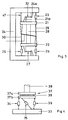
- the test frame consists of a base plate 1, which rests on a foundation 2. Furthermore, vertical supports 3 and 4 connected to the base plate 1 are provided, which are connected at the upper end to a height-displaceable abutment 5.
- the component 6 to be tested is firmly connected at its lower cut surface to a load head 7 designed as a plate arrangement. The upper free end of component 6 is supported on the abutment.
- a load pendulum 8 is attached to the load head 7 with its upper free end at the articulation point 9.
- the lower free end of the load pendulum 8 is connected to the base plate 1 at the articulation point 10.
- the load pendulum 8 is only longitudinally displaceable and is equipped with a hydraulically drivable piston-cylinder arrangement 11 for this purpose.
- a measuring sensor 12 is provided, which consists of suitable force and displacement sensors.
- the load pendulum 13 is designed, which is also articulated on the load plate 7 and on the base plate 1. Furthermore, a load pendulum 14 of identical construction to the load pendulums 8 and 13 is provided, which is articulated on the one hand on a downwardly projecting support lever 7a of the load plate 7 and on the other hand on an upwardly projecting support lever 1a of the base plate 1. On the load head 7 is also a upward support arm 15 attached. Another support arm 16 is attached to the abutment 5 and directed downwards. Between the free end 15a of the support arm 15 and the point 5a on the abutment 5, a measuring pendulum 17 for measuring the distance between the points 5a and 15a is arranged.
- Another measuring pendulum 18 is provided between the points 7b of the load plate 7 and the free end 16a of the support arm 16.
- a third measuring pendulum 20 is located between points 15a and 16a.
- the test device shown in FIG. 1 is set up for three degrees of freedom. So this is a flat test arrangement.
- all boundary conditions can be applied to the component 6 to be tested via the load head 7.
- the loading takes place in arbitrarily small stages, whereby the stiffness matrix for the component must be estimated for the first loading stage.
- suitable displacement of the load pendulums 8, 13 and 14 with respect to the initial state at the start of the test with the component 6 unloaded all of the load and displacement variables compatible with it and thus also all boundary conditions can be applied.
- the forces acting from the load head 7 are detected by the sensors of the load pendulums 8, 13 and 14.
- the normal forces and the bending moments in the load pendulums are measured on two different cross sections, so that their transverse forces can also be determined.
- the measurement of the normal forces in the load pendulums would suffice.
- the other force quantities are required to detect the friction in the articulation points, so that these are eliminated by appropriate compensation of the friction forces and thus do not cause a measurement error.
- the spatial displacement of the bearing surface 7c for the component 6 on the load head 7 is determined with the aid of the measuring pendulums 17, 18 and 20.
- All measured values of the measuring pendulums and measuring sensors in the load pendulums are fed to a process computer 41 shown in FIG. 2, which forms part of a control device 40.
- the load head 7 is actuated by the drive device 42, which consists of the load suspension 8, 13, 14 in Fig. 1.
- the spatial displacements of the load head 7 are detected by the measuring device 43, which comprises the force and measuring sensors 12, 13a, 14a, 17, 18, 20 shown in FIG. 1.
- the control device 40 also contains the program modules 44, 45, 46 of the process computer 41.
- the boundary conditions for the component 6 to be tested can be fed to the module 44 in a freely programmable manner according to arrow 44a in FIG. 2.
- the measured values of the spatial displacement of the load head 7 are transferred from the measuring device 43 to the module 45.
- These suitably transformed actual values of the boundary conditions contained in module 45 are fed with the corresponding setpoints of module 44 to a further module 46, in which the controlled variable for drive device 42 is determined.
- the control is carried out step by step in order to be able to determine its load-bearing behavior even in the case of non-linear relationships between force and displacement variables, i.e. in the plastic area of the component to be tested. In this way, a stiffness matrix estimated for the first load level before the start of the test can be determined step by step.
- the examination of a component with load-dependent boundary conditions can be carried out with the new test device using suitable programming.
- the boundary conditions are not fixed according to arrow 44a, but are specified in a superimposed program loop depending on the experimental result as variable setpoints.
- the behavior of an entire structure can thus be determined, that in an experimentally in the test device and in a section treated only mathematically is broken down, the internal forces being determined iteratively.
- Fig. 3 shows a simplified representation of a test device which is equipped with a second load head 21 instead of a fixed abutment.
- a longitudinally displaceable load pendulum 23 is articulated on the one hand on the load head 21 and on the other hand on the test frame 24.
- a load pendulum 32 is articulated between the end points of a support lever 21a of the load head 21, which, however, is not displaceable in length.
- the lower load head 22 is connected to the longitudinally displaceable load pendulum 25 and 26 and to a rigid load pendulum 27.
- a component 28 to be tested is firmly connected at its ends to the load heads 21 and 22, respectively.
- Measuring pendulums 29, 30 and 31, which are arranged similarly to the embodiment according to FIG. 1, are used to determine the mutual displacement of the load heads 21 and 22.
- the space requirement can be further reduced by replacing rigid load pendulums with longitudinally displaceable load pendulums.
- FIG. 4 shows a section of a testing device modified compared to FIGS. 1 and 3.
- the lower ends of load pendulums 34, 35 and 36 are articulated on a base plate 33, while their upper ends are hinged to a load head 37.
- the load head 37 consists of an upper plate 37a and a lower plate 37b with the articulation points of the load pendulums 34, 35 and 36.
- the upper plate 37a of the load head 37 is firmly connected to a component 38 to be tested, which is only shown in sections.
Landscapes
- Engineering & Computer Science (AREA)
- Aviation & Aerospace Engineering (AREA)
- Physics & Mathematics (AREA)
- General Physics & Mathematics (AREA)
- Investigating Strength Of Materials By Application Of Mechanical Stress (AREA)
Claims (8)
- Dispositif d'essai pour éléments de construction en forme de barre, en particulier des parties d'armature porteuse d'un ouvrage d'art, comportant principalement un bâti d'essai avec au moins un organe de butée destiné à recevoir les efforts agissant sur l'élément en cours d'essai, au moins une tête de charge déplaçable reliée à un dispositif de commande en vue d'exercer les efforts sur ledit élément, ainsi que des dispositifs de mesure pour la détermination des valeurs des efforts appliqués sur ladite tête de charge par le dispositif de commande, caractérisé en ce que la tête de charge (7, 21, 22, 37) présente une surface d'appui (7c) qui est déplaçable en vue du réglage de conditions aux limites pouvant être choisies arbitrairement pour ledit élément (6, 28, 38) pour un nombre quelconque de degrés de liberté, et qui peut être rendue solidaire dudit élément (6, 28, 38) pour toutes ces conditions aux limites, en ce que les dispositifs de mesure (12, 13a, 14a, 20) sont prévues en vue de la détermination vectorielle des valeurs des forces pour tous les degrés de liberté prévus, en ce que des dispositifs de mesure complémentaires (17, 18, 20, 29, 30, 31) sont incorporés en vue de la détermination des déplacements dans l'espace de la surface d'appui (7c) par rapport à l'organe de butée (5) qui lui fait face, et en ce qu'on prévoit pour le déplacement de la tête de charge (7, 21, 22, 37) un dispositif de régulation (40) dans lequel on peut déterminer au moyen d'un calculateur (41) une grandeur de régulation pour le dispositif de commande à partir des valeurs des mesures transmises par les dispositifs de mesure (43) et des valeurs assignées choisies au préalable pour les conditions aux limites.
- Dispositif d'essai selon la revendication 1, caractérisé en ce qu'on prévoit comme dispositif de commande pour chaque degré de liberté, un pendule de charge (8, 13, 14, 22, 23, 25, 26, 34, 35, 36) déplaçable longitudinalement qui est articulé sur le bâti d'essai par l'une de ses extrémités et sur la tête de charge (7, 21, 22, 37) par l'autre de ses extrémités.
- Dispositif d'essai selon la revendication 2, caractérisé en ce que les pendules de charge (8) sont réalisés sous la forme de dispositifs à vérins hydrauliques (11) qui peuvent être chargés à leurs deux extrémités.
- Dispositif d'essai selon l'une des revendications 2 ou 3, caractérisé en ce que la tête de charge (31) est réalisée sous la forme d'un dispositif à platines aux zones périphériques de laquelle sont articulés les pendules de charge (8, 13, 14).
- Dispositif d'essai selon l'une des revendications 2 à 4, caractérisé en ce qu'il est prévu sur chaque pendule de charge (8, 13, 14), pour la détermination vectorielle des valeurs des forces appliquées sur la tête de charge (7), deux enregistreurs d'effort disposés axialement à une certaine distance l'un de l'autre, pour la mesure des efforts normaux et des moments de flexion dans deux sections transversales du pendule de charge, ainsi qu'un enregistreur de déplacement.
- Dispositif d'essai selon l'une des revendications ci-dessus, caractérisé en ce que la tête de charge (37) est constituée par deux platines (37a, 37b) sensiblement de même surface, dont l'une (37a) comporte la surface d'appui et l'autre (37b) est reliée au dispositif de commande, et en ce que des éléments de mesure des efforts (39) par un nombre de composantes correspondant aux degrés de liberté, sont disposés entre lesdites platines.
- Dispositif d'essai selon l'une des revendications ci-dessus, caractérisé en ce qu'un pendule de mesure (17, 18, 20) est disposé entre la tête de charge (7) et l'organe de butée (5) qui lui fait face en vue de la détermination du déplacement dans l'espace de ladite surface d'appui (7c) pour chacun des degrés de liberté.
- Dispositif d'essai selon l'une des revendications ci-dessus, caractérisé en ce que l'organe de butée faisant face à la tête de charge (22) est réalisé lui-même sous la forme d'une autre tête de charge (21) qui est déplaçable par un autre dispositif de commande.
Priority Applications (1)
| Application Number | Priority Date | Filing Date | Title |
|---|---|---|---|
| AT85903219T ATE87097T1 (de) | 1984-07-10 | 1985-07-04 | Pruefvorrichtung fuer stabformige bauteile, insbesondere tragwerksabschnitt des ingenieurbaus. |
Applications Claiming Priority (2)
| Application Number | Priority Date | Filing Date | Title |
|---|---|---|---|
| DE3425359 | 1984-07-10 | ||
| DE3425359A DE3425359C2 (de) | 1984-07-10 | 1984-07-10 | Prüfvorrichtung für stabförmige Bauteile, insbesondere Tragwerksabschnitt des Ingenieurbaus |
Publications (2)
| Publication Number | Publication Date |
|---|---|
| EP0187784A1 EP0187784A1 (fr) | 1986-07-23 |
| EP0187784B1 true EP0187784B1 (fr) | 1993-03-17 |
Family
ID=6240267
Family Applications (1)
| Application Number | Title | Priority Date | Filing Date |
|---|---|---|---|
| EP85903219A Expired - Lifetime EP0187784B1 (fr) | 1984-07-10 | 1985-07-04 | Dispositif d'essai pour elements en forme de barre, en particulier un segment d'ossature porteuse d'un ouvrage d'art |
Country Status (5)
| Country | Link |
|---|---|
| EP (1) | EP0187784B1 (fr) |
| JP (1) | JPS62501098A (fr) |
| AT (1) | ATE87097T1 (fr) |
| DE (2) | DE3425359C2 (fr) |
| WO (1) | WO1986000702A1 (fr) |
Cited By (1)
| Publication number | Priority date | Publication date | Assignee | Title |
|---|---|---|---|---|
| CN109489922A (zh) * | 2018-11-15 | 2019-03-19 | 华北科技学院 | 一种用于测试柔性支架力学性能的试验装置 |
Families Citing this family (4)
| Publication number | Priority date | Publication date | Assignee | Title |
|---|---|---|---|---|
| US5056370A (en) * | 1990-07-19 | 1991-10-15 | Wolfgang Maier | Method and apparatus for testing a test piece |
| DE4204589A1 (de) * | 1992-02-15 | 1993-08-19 | Mtu Muenchen Gmbh | Werkstoffpruefvorrichtung fuer zug- oder druckversuche |
| KR100751578B1 (ko) * | 1999-08-25 | 2007-08-28 | 포레시아 이그조스트 시스템즈, 인코포레이티드 | 시뮬레이션 테스트용 이중 마스트 시스템 |
| RU2222800C1 (ru) * | 2002-07-11 | 2004-01-27 | Открытое акционерное общество "Центр технической диагностики" | Стенд для испытания труб внутренним давлением и на изгиб и гидравлическая система стенда |
Family Cites Families (2)
| Publication number | Priority date | Publication date | Assignee | Title |
|---|---|---|---|---|
| US2446566A (en) * | 1946-01-22 | 1948-08-10 | Jr Edward Wenk | Model testing apparatus |
| JPS5619744B2 (fr) * | 1974-10-01 | 1981-05-09 |
-
1984
- 1984-07-10 DE DE3425359A patent/DE3425359C2/de not_active Expired
-
1985
- 1985-07-04 JP JP60503128A patent/JPS62501098A/ja active Granted
- 1985-07-04 AT AT85903219T patent/ATE87097T1/de not_active IP Right Cessation
- 1985-07-04 DE DE8585903219T patent/DE3587193D1/de not_active Expired - Fee Related
- 1985-07-04 EP EP85903219A patent/EP0187784B1/fr not_active Expired - Lifetime
- 1985-07-04 WO PCT/DE1985/000228 patent/WO1986000702A1/fr not_active Ceased
Cited By (1)
| Publication number | Priority date | Publication date | Assignee | Title |
|---|---|---|---|---|
| CN109489922A (zh) * | 2018-11-15 | 2019-03-19 | 华北科技学院 | 一种用于测试柔性支架力学性能的试验装置 |
Also Published As
| Publication number | Publication date |
|---|---|
| DE3425359A1 (de) | 1986-01-30 |
| DE3425359C2 (de) | 1986-12-11 |
| ATE87097T1 (de) | 1993-04-15 |
| JPH037896B2 (fr) | 1991-02-04 |
| JPS62501098A (ja) | 1987-04-30 |
| WO1986000702A1 (fr) | 1986-01-30 |
| EP0187784A1 (fr) | 1986-07-23 |
| DE3587193D1 (de) | 1993-04-22 |
Similar Documents
| Publication | Publication Date | Title |
|---|---|---|
| DE2758340C2 (fr) | ||
| DE2209845A1 (de) | Meßgerät, insbesondere Lagerung für Meßfühler | |
| DE3331708C2 (fr) | ||
| EP3845874A1 (fr) | Console d'étagère | |
| DE102007036214B4 (de) | Automatisierte Eigengewichtskraftmessmaschine zur Kalibrierung von Dehnungsmesskraftaufnehmern | |
| EP2408590B1 (fr) | Procédé et dispositif pour installer une machine | |
| EP3191236B1 (fr) | Presse plieuse et procédé de pliage d'une pièce à l'aide de la presse plieuse | |
| DE102014215189A1 (de) | Verfahren des erneuten Einbauens eines Gegenstandes, welcher gelagert werden soll | |
| DE3440670A1 (de) | Einrichtung zum messen der auf maschinenbauteile wirkenden kraefte | |
| DE3425359C2 (de) | Prüfvorrichtung für stabförmige Bauteile, insbesondere Tragwerksabschnitt des Ingenieurbaus | |
| DE2926213A1 (de) | Pyramidenwaage zur ermittlung von kraeften und momenten, insbesondere in windkanaelen | |
| DE2746346A1 (de) | Vorrichtung zur ermittlung des schwerpunktes und der standsicherheitsgrenzwinkel von arbeitsmaschinen | |
| DE1806668B2 (de) | Druckkraftmessdose | |
| DE19939549A1 (de) | Prufstand zum Messen der Beulsteifigkeit von Bauteilen | |
| DE3113753C2 (de) | Dreiwalzenbiegemaschine für Blech | |
| EP0212448B1 (fr) | Dispositif pour décomposer des forces vectorielles | |
| DE3927475C2 (fr) | ||
| DE3121373A1 (de) | Geraet zum insbesondere dreidimensionalen messen und/oder anreissen und/oder antasten von werkstuecken | |
| DE2331149B2 (de) | Abstützung der mit einer Meßdose verbundenen Lastbrücke einer Brückenwaage | |
| DE102014117244A1 (de) | Koordinatenmessgerät und Verfahren zur Kompensation großer Werkstückmassen | |
| DE102019112909B4 (de) | Prüfstand für die Brücke eines Karosserietunnels und Verwendung eines solchen Prüfstandes | |
| DE10254062B4 (de) | Verfahren und Vorrichtung zur Bestimmung von Schüttgutparametern | |
| DE102024100005A1 (de) | Härteprüfgerät, das über einen rotierenden Kopf, der auf einem Kippsystem montiert ist, verfügt | |
| DE2156410A1 (de) | Waage | |
| DE2654330A1 (de) | Verfahren und einrichtung zur graduierung oder eichung von dynamometern |
Legal Events
| Date | Code | Title | Description |
|---|---|---|---|
| PUAI | Public reference made under article 153(3) epc to a published international application that has entered the european phase |
Free format text: ORIGINAL CODE: 0009012 |
|
| 17P | Request for examination filed |
Effective date: 19860308 |
|
| AK | Designated contracting states |
Kind code of ref document: A1 Designated state(s): AT BE CH DE FR GB IT LI NL SE |
|
| 17Q | First examination report despatched |
Effective date: 19870811 |
|
| 18D | Application deemed to be withdrawn |
Effective date: 19880201 |
|
| 18RA | Request filed for re-establishment of rights before grant |
Effective date: 19890113 |
|
| 19U | Interruption of proceedings before grant |
Effective date: 19870731 |
|
| 19W | Proceedings resumed before grant after interruption of proceedings |
Effective date: 19890113 |
|
| D18D | Application deemed to be withdrawn (deleted) | ||
| R18Z | Request filed for re-establishment of rights before grant (corrected) | ||
| GRAA | (expected) grant |
Free format text: ORIGINAL CODE: 0009210 |
|
| AK | Designated contracting states |
Kind code of ref document: B1 Designated state(s): AT BE CH DE FR GB IT LI NL SE |
|
| REF | Corresponds to: |
Ref document number: 87097 Country of ref document: AT Date of ref document: 19930415 Kind code of ref document: T |
|
| REF | Corresponds to: |
Ref document number: 3587193 Country of ref document: DE Date of ref document: 19930422 |
|
| GBT | Gb: translation of ep patent filed (gb section 77(6)(a)/1977) |
Effective date: 19930406 |
|
| PGFP | Annual fee paid to national office [announced via postgrant information from national office to epo] |
Ref country code: SE Payment date: 19930611 Year of fee payment: 9 |
|
| ITF | It: translation for a ep patent filed | ||
| PGFP | Annual fee paid to national office [announced via postgrant information from national office to epo] |
Ref country code: FR Payment date: 19930618 Year of fee payment: 9 |
|
| PGFP | Annual fee paid to national office [announced via postgrant information from national office to epo] |
Ref country code: GB Payment date: 19930622 Year of fee payment: 9 |
|
| PGFP | Annual fee paid to national office [announced via postgrant information from national office to epo] |
Ref country code: BE Payment date: 19930705 Year of fee payment: 9 |
|
| PGFP | Annual fee paid to national office [announced via postgrant information from national office to epo] |
Ref country code: AT Payment date: 19930712 Year of fee payment: 9 |
|
| ET | Fr: translation filed | ||
| PGFP | Annual fee paid to national office [announced via postgrant information from national office to epo] |
Ref country code: CH Payment date: 19930727 Year of fee payment: 9 |
|
| PGFP | Annual fee paid to national office [announced via postgrant information from national office to epo] |
Ref country code: NL Payment date: 19930731 Year of fee payment: 9 |
|
| PLBE | No opposition filed within time limit |
Free format text: ORIGINAL CODE: 0009261 |
|
| STAA | Information on the status of an ep patent application or granted ep patent |
Free format text: STATUS: NO OPPOSITION FILED WITHIN TIME LIMIT |
|
| 26N | No opposition filed | ||
| PG25 | Lapsed in a contracting state [announced via postgrant information from national office to epo] |
Ref country code: GB Effective date: 19940704 Ref country code: AT Effective date: 19940704 |
|
| PG25 | Lapsed in a contracting state [announced via postgrant information from national office to epo] |
Ref country code: SE Effective date: 19940705 |
|
| PG25 | Lapsed in a contracting state [announced via postgrant information from national office to epo] |
Ref country code: LI Effective date: 19940731 Ref country code: CH Effective date: 19940731 Ref country code: BE Effective date: 19940731 |
|
| BERE | Be: lapsed |
Owner name: MAIER WOLFGANG Effective date: 19940731 |
|
| EUG | Se: european patent has lapsed |
Ref document number: 85903219.5 Effective date: 19950210 |
|
| PG25 | Lapsed in a contracting state [announced via postgrant information from national office to epo] |
Ref country code: NL Effective date: 19950201 |
|
| GBPC | Gb: european patent ceased through non-payment of renewal fee |
Effective date: 19940704 |
|
| NLV4 | Nl: lapsed or anulled due to non-payment of the annual fee | ||
| PGFP | Annual fee paid to national office [announced via postgrant information from national office to epo] |
Ref country code: DE Payment date: 19950321 Year of fee payment: 10 |
|
| PG25 | Lapsed in a contracting state [announced via postgrant information from national office to epo] |
Ref country code: FR Effective date: 19950331 |
|
| REG | Reference to a national code |
Ref country code: CH Ref legal event code: PL |
|
| EUG | Se: european patent has lapsed |
Ref document number: 85903219.5 |
|
| REG | Reference to a national code |
Ref country code: FR Ref legal event code: ST |
|
| PG25 | Lapsed in a contracting state [announced via postgrant information from national office to epo] |
Ref country code: DE Effective date: 19960402 |