EP0187794B1 - Vorrichtung für wärmeaustausch, verwendbar als intermittierende absorptionssolarkälteanlage - Google Patents
Vorrichtung für wärmeaustausch, verwendbar als intermittierende absorptionssolarkälteanlage Download PDFInfo
- Publication number
- EP0187794B1 EP0187794B1 EP85903299A EP85903299A EP0187794B1 EP 0187794 B1 EP0187794 B1 EP 0187794B1 EP 85903299 A EP85903299 A EP 85903299A EP 85903299 A EP85903299 A EP 85903299A EP 0187794 B1 EP0187794 B1 EP 0187794B1
- Authority
- EP
- European Patent Office
- Prior art keywords
- generator
- condenser
- evaporator
- gas
- pressure
- Prior art date
- Legal status (The legal status is an assumption and is not a legal conclusion. Google has not performed a legal analysis and makes no representation as to the accuracy of the status listed.)
- Expired
Links
- 238000010521 absorption reaction Methods 0.000 title claims abstract description 10
- 239000000126 substance Substances 0.000 claims abstract description 7
- QGZKDVFQNNGYKY-UHFFFAOYSA-N Ammonia Chemical compound N QGZKDVFQNNGYKY-UHFFFAOYSA-N 0.000 claims description 10
- 230000002745 absorbent Effects 0.000 claims description 6
- 239000002250 absorbent Substances 0.000 claims description 6
- 239000007788 liquid Substances 0.000 claims description 6
- 230000000694 effects Effects 0.000 claims description 5
- 150000003839 salts Chemical class 0.000 claims description 4
- 229910001615 alkaline earth metal halide Inorganic materials 0.000 claims description 3
- 230000005855 radiation Effects 0.000 claims description 3
- UXVMQQNJUSDDNG-UHFFFAOYSA-L Calcium chloride Chemical compound [Cl-].[Cl-].[Ca+2] UXVMQQNJUSDDNG-UHFFFAOYSA-L 0.000 claims description 2
- 230000009471 action Effects 0.000 claims description 2
- 238000004378 air conditioning Methods 0.000 claims description 2
- 229910001628 calcium chloride Inorganic materials 0.000 claims description 2
- 239000001110 calcium chloride Substances 0.000 claims description 2
- 239000003638 chemical reducing agent Substances 0.000 claims description 2
- 238000001704 evaporation Methods 0.000 claims description 2
- 230000008020 evaporation Effects 0.000 claims description 2
- 239000003795 chemical substances by application Substances 0.000 claims 1
- 239000011521 glass Substances 0.000 claims 1
- 239000006096 absorbing agent Substances 0.000 abstract description 12
- 239000003507 refrigerant Substances 0.000 description 9
- 230000009102 absorption Effects 0.000 description 7
- 238000005057 refrigeration Methods 0.000 description 5
- 229910000831 Steel Inorganic materials 0.000 description 4
- 239000010959 steel Substances 0.000 description 4
- XLYOFNOQVPJJNP-UHFFFAOYSA-N water Substances O XLYOFNOQVPJJNP-UHFFFAOYSA-N 0.000 description 3
- 229910021529 ammonia Inorganic materials 0.000 description 2
- 238000001816 cooling Methods 0.000 description 2
- 238000010438 heat treatment Methods 0.000 description 2
- 229960005486 vaccine Drugs 0.000 description 2
- 230000002528 anti-freeze Effects 0.000 description 1
- 230000000712 assembly Effects 0.000 description 1
- 238000000429 assembly Methods 0.000 description 1
- 230000000903 blocking effect Effects 0.000 description 1
- 239000011575 calcium Substances 0.000 description 1
- 239000011248 coating agent Substances 0.000 description 1
- 238000000576 coating method Methods 0.000 description 1
- 230000002860 competitive effect Effects 0.000 description 1
- 239000000470 constituent Substances 0.000 description 1
- 230000007797 corrosion Effects 0.000 description 1
- 238000005260 corrosion Methods 0.000 description 1
- 238000010586 diagram Methods 0.000 description 1
- 238000010494 dissociation reaction Methods 0.000 description 1
- 230000005593 dissociations Effects 0.000 description 1
- 239000000374 eutectic mixture Substances 0.000 description 1
- 238000002474 experimental method Methods 0.000 description 1
- 238000009920 food preservation Methods 0.000 description 1
- 235000015243 ice cream Nutrition 0.000 description 1
- 238000009533 lab test Methods 0.000 description 1
- 239000000463 material Substances 0.000 description 1
- 235000013372 meat Nutrition 0.000 description 1
- 238000004321 preservation Methods 0.000 description 1
- 230000009103 reabsorption Effects 0.000 description 1
- 238000007789 sealing Methods 0.000 description 1
- 239000007787 solid Substances 0.000 description 1
- 238000004381 surface treatment Methods 0.000 description 1
- 230000004083 survival effect Effects 0.000 description 1
- 230000007704 transition Effects 0.000 description 1
- 238000009834 vaporization Methods 0.000 description 1
- 230000008016 vaporization Effects 0.000 description 1
Images


Classifications
-
- F—MECHANICAL ENGINEERING; LIGHTING; HEATING; WEAPONS; BLASTING
- F25—REFRIGERATION OR COOLING; COMBINED HEATING AND REFRIGERATION SYSTEMS; HEAT PUMP SYSTEMS; MANUFACTURE OR STORAGE OF ICE; LIQUEFACTION SOLIDIFICATION OF GASES
- F25B—REFRIGERATION MACHINES, PLANTS OR SYSTEMS; COMBINED HEATING AND REFRIGERATION SYSTEMS; HEAT PUMP SYSTEMS
- F25B27/00—Machines, plants or systems, using particular sources of energy
- F25B27/002—Machines, plants or systems, using particular sources of energy using solar energy
- F25B27/007—Machines, plants or systems, using particular sources of energy using solar energy in sorption type systems
-
- F—MECHANICAL ENGINEERING; LIGHTING; HEATING; WEAPONS; BLASTING
- F24—HEATING; RANGES; VENTILATING
- F24S—SOLAR HEAT COLLECTORS; SOLAR HEAT SYSTEMS
- F24S23/00—Arrangements for concentrating solar-rays for solar heat collectors
- F24S23/70—Arrangements for concentrating solar-rays for solar heat collectors with reflectors
- F24S23/74—Arrangements for concentrating solar-rays for solar heat collectors with reflectors with trough-shaped or cylindro-parabolic reflective surfaces
-
- F—MECHANICAL ENGINEERING; LIGHTING; HEATING; WEAPONS; BLASTING
- F25—REFRIGERATION OR COOLING; COMBINED HEATING AND REFRIGERATION SYSTEMS; HEAT PUMP SYSTEMS; MANUFACTURE OR STORAGE OF ICE; LIQUEFACTION SOLIDIFICATION OF GASES
- F25B—REFRIGERATION MACHINES, PLANTS OR SYSTEMS; COMBINED HEATING AND REFRIGERATION SYSTEMS; HEAT PUMP SYSTEMS
- F25B17/00—Sorption machines, plants or systems, operating intermittently, e.g. absorption or adsorption type
- F25B17/08—Sorption machines, plants or systems, operating intermittently, e.g. absorption or adsorption type the absorbent or adsorbent being a solid, e.g. salt
-
- Y—GENERAL TAGGING OF NEW TECHNOLOGICAL DEVELOPMENTS; GENERAL TAGGING OF CROSS-SECTIONAL TECHNOLOGIES SPANNING OVER SEVERAL SECTIONS OF THE IPC; TECHNICAL SUBJECTS COVERED BY FORMER USPC CROSS-REFERENCE ART COLLECTIONS [XRACs] AND DIGESTS
- Y02—TECHNOLOGIES OR APPLICATIONS FOR MITIGATION OR ADAPTATION AGAINST CLIMATE CHANGE
- Y02A—TECHNOLOGIES FOR ADAPTATION TO CLIMATE CHANGE
- Y02A30/00—Adapting or protecting infrastructure or their operation
- Y02A30/27—Relating to heating, ventilation or air conditioning [HVAC] technologies
-
- Y—GENERAL TAGGING OF NEW TECHNOLOGICAL DEVELOPMENTS; GENERAL TAGGING OF CROSS-SECTIONAL TECHNOLOGIES SPANNING OVER SEVERAL SECTIONS OF THE IPC; TECHNICAL SUBJECTS COVERED BY FORMER USPC CROSS-REFERENCE ART COLLECTIONS [XRACs] AND DIGESTS
- Y02—TECHNOLOGIES OR APPLICATIONS FOR MITIGATION OR ADAPTATION AGAINST CLIMATE CHANGE
- Y02B—CLIMATE CHANGE MITIGATION TECHNOLOGIES RELATED TO BUILDINGS, e.g. HOUSING, HOUSE APPLIANCES OR RELATED END-USER APPLICATIONS
- Y02B30/00—Energy efficient heating, ventilation or air conditioning [HVAC]
- Y02B30/62—Absorption based systems
-
- Y—GENERAL TAGGING OF NEW TECHNOLOGICAL DEVELOPMENTS; GENERAL TAGGING OF CROSS-SECTIONAL TECHNOLOGIES SPANNING OVER SEVERAL SECTIONS OF THE IPC; TECHNICAL SUBJECTS COVERED BY FORMER USPC CROSS-REFERENCE ART COLLECTIONS [XRACs] AND DIGESTS
- Y02—TECHNOLOGIES OR APPLICATIONS FOR MITIGATION OR ADAPTATION AGAINST CLIMATE CHANGE
- Y02E—REDUCTION OF GREENHOUSE GAS [GHG] EMISSIONS, RELATED TO ENERGY GENERATION, TRANSMISSION OR DISTRIBUTION
- Y02E10/00—Energy generation through renewable energy sources
- Y02E10/40—Solar thermal energy, e.g. solar towers
Definitions
- the present invention relates to a heat exchange device, in particular usable as a solar refrigerator with intermittent absorption, and more particularly intended for tropical countries deprived of any energy other than solar energy. Indeed, the cooling needs of deprived tropical zones are essential to ensure the survival of their occupants. The preservation of perishable foodstuffs, in particular meats and vaccines cannot be ensured without refrigeration. However, these regions generally belong to poor countries and are deprived of any energy resource other than the sun.
- An object of the present invention is to provide a solar refrigerator capable of operating autonomously with a 24 hour refrigeration cycle without any other source of energy than solar energy.
- Another object of the present invention is to prevent an accidental rise in temperature in the insulating tank in the refrigeration circuit, without using a particularly sophisticated exchanger, but only a condenser cooled by the ambiant air.
- Yet another object of the present invention is to provide a solar refrigerator with a design that is both simple and robust, without having to use moving parts or water, thus avoiding internal corrosion, while avoiding too frequent interventions of the user for setting the device, this solar refrigerator can be manufactured at a very competitive cost price.
- the present invention therefore relates to a heat exchange device, in particular usable as a refrigerator actuated by means of solar energy by intermittent absorption, this device comprising, mounted on a frame, an absorber generator, a condenser and an evaporator arranged in an insulating tank, the absorber generator comprising at least one absorbing generator element constituted by a system for focusing the sun's rays along a focal line, this system cooperating with a hollow tubular element whose axis coincides with said focal line, and which contains a gas supply arrangement, this hollow tubular element being charged with an absorbent substance capable of creating with the gas a blow the efficient refrigerant, this device being characterized in that a non-return valve is provided between the generator and the condenser thus a stop valve, this stop valve which is arranged in the insulating tank of the evaporator, being controlled linked by the pressure difference between the generator and the condenser so as to close the access from the condenser to the evaporator, when the
- the shut-off valve has at its lower part a pressure reducer which increases the cooling effect at the time of the passage of the refrigerant liquid;
- the focusing system is constituted by a cylindroparabolic mirror covered by a window intended to add the greenhouse effect to the focusing;
- the gas supply arrangement is a hollow tubular element mounted coaxially in the tubular element containing the absorbent substance, and comprising a certain number of through holes; peripherally to the internal tubular element is provided a trellis having a mesh width suitable for opposing the passage of the absorbent substance;
- the refrigerant couple consists of an alkaline earth metal halide, preferably calcium chloride, and ammonia gas;
- the constituent elements of the absorber generator are mounted on the upper plane of the frame, this upper plane having with respect to the horizontal plane of the ground an inclination equal in degrees to the latitude of the place of positioning of the thermal device; between the generator and the condenser is mounted a non-return valve, between the a
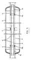
- the generator 1 is made up of a certain number of generator-absorber elements, each of them being made up of a focusing element 5 made up of a housing or tank 5a inside. which is mounted a cylindroparabolic mirror 5b covered by a window 5d intended to add the greenhouse effect to the focusing.
- a cylindroparabolic mirror 5b covered by a window 5d intended to add the greenhouse effect to the focusing.
- vertical grooves 5c In the axis of the focal line of the cylindroparabolic mirror 5b, vertical grooves 5c have been provided. These grooves 5c being intended to receive an absorbing tubular element 6, which will thus be centered coaxially to the focal line of the cylindroparabolic mirror 5b.
- the elements 6 are coupled in pairs to an ammonia gas supply system, so as to form a quadrangular tube system, the elements 6 being arranged symmetrically and parallel to a central tube 7.
- each generator-absorber element 6 coaxially comprises a tube 8, the ends 8a, 8b of which are fitted coaxially in the extensions of the tubular connections 9 welded to the element 6. Joints 10a, 10b are provided to guarantee sealing at the connection of the tubular element 8 and the pipe 9.
- the internal tubular element 8 is centered inside the tubular element 6 by means of at least one lug 11, and has a certain number of through holes 12.
- a trellis 15 having a mesh size allowing the passage of the ammonia gas while preventing the grains of absorbent surface contained in the element 6 from coming in contact with the element 8 to plug the holes 12.
- the elements 6, 8 and 9 are constituted by steel tubes, the external face of the element 6 being covered with a selective coating constituted by covering sheets of a material suitable for its actinic absorption, or else obtained by an appropriate surface treatment of the tubular elements 6.
- cylindroparabolic mirror 5b is meant curved mirrors of parabolic section defining a parabolic surface having for its center a straight line.
- Each mirror 5a is protected by a window 5b and can be rotated, more or less 23 ° around the common fixed axis.
- Rotation limiting stops are arranged on the frame so as to limit the rotation of said sets of cylindroparabolic mirrors.
- the assemblies 5, 6 are arranged on the upper plane of a frame, this upper plane forming with the horizontal plane of the frame an angle of inclination equal in degrees to the latitude of the place of operation of the thermal device, the tanks 5a being mounted so that they can be rotated ⁇ 25 ° from a.
- the condenser 2 consists of finned steel tubes 2a and connected downstream to a steel buffer tank 4 which is itself connected to an evaporator 3a placed in an insulating tank 3, and consisting of an assembly of tubes in steel.
- a cold storage tank not shown in the drawings, and advantageously constituted by a flexible enclosure inside which an eutectic mixture, for example antifreeze, has been loaded, this reservoir being able to be replaced by compartments full of water if one simply wishes to obtain loaves of ice.
- the thermal device according to the present invention also comprises an arrangement of valves or flaps intended to ensure its operating autonomy.
- This arrangement advantageously consists of three automatic valves I, II, III, operating only under the influence of the pressure of the ammonia gas, and forcing it to circulate for perfectly defined periods as a function of time and external parameters, always in the Same direction.
- the valve 1 which is mounted between the generator and the condenser, allows, during the heating of the salt which dissociates the ammoniacate, the passage of the compressed gas towards the condenser and prohibits its direct reabsorption by the salt during nighttime evaporation.
- Valve II mounted between the evaporator and the generator, isolates the evaporator 3a from the generator during the daytime phase so that the gas released to the generator 1 does not come to condense directly in the evaporator 3a and heat it, which would make it impossible to keep perishable products or foodstuffs.
- This valve It opens at night following the depression prevailing in the generator 1 and thus allows the passage of the gas sucked in by the partially dissociated salt, the blocking at pressure being able to reach 30 bars (3 MPa), while the transition to depression is negligible.
- the condenser 2, the evaporator 3a and the generator 1 are joined by a stop valve or differential valve III, this valve acts as a gas blocker system and simultaneously filters the liquid.
- This valve shown in FIG. 5, is normally closed when the pressure P2 at the condenser is substantially the same as the pressure P1 at the generator, and comprises at its lower part a regulator, for example a capillary, the role of which is to obtain cold by additional expansion of the liquid when at the end of the day the ammonia will pass from the buffer tank to the evaporator.
- This valve allows the device to operate continuously, despite certain intermittences of solar radiation, in which case the condenser 2 will contain only gas which, without the presence of this valve III would go, via the condenser 2, condensing in the evaporator 3a by heating it according to the Watt principle or from the cold wall, the condenser no longer playing its role.
- refrigerant couples based on an alkaline earth metal halide and ammonia can be used in the thermal refrigeration device according to the invention
- one of the original features of the invention consists in using a refrigerant couple Ca -C1 2 , NH 3 which has already had a certain development on an industrial scale, but the mode of use of which, which draws the energy necessary for the dissociation of the ammoniacates generated by said refrigerant couple, is carried out only by solar radiation .
- the unit element of the generator can be, for example, a module formed by two focal tubes (6) each occupying a sensor tank (5), these tubes being joined by a central tube (7) located between the tanks, thus allowing a indefinite extension of the catchment area.
- the realization of the generator in modular form lends itself to indefinite extensions whose surface can vary from a few square meters to a few tens of square meters without modifying the following chain: condenser-evaporator if not in its dimensions and its possibilities.
- domestic air conditioning can be envisaged by releasing the evaporator from the insulating tank.
- the solar thermal machine of the invention can also be used at night as a heat pump in desert areas because of the relatively high temperature (approximately 70 ° C.) of the refrigerant couple during the 'night absorption.
- a simplified presentation of the assembly can be used for making ice cream without any particular concern for food preservation.
Landscapes
- Engineering & Computer Science (AREA)
- Physics & Mathematics (AREA)
- Mechanical Engineering (AREA)
- Thermal Sciences (AREA)
- General Engineering & Computer Science (AREA)
- Life Sciences & Earth Sciences (AREA)
- Sustainable Development (AREA)
- Sustainable Energy (AREA)
- Chemical & Material Sciences (AREA)
- Combustion & Propulsion (AREA)
- Sorption Type Refrigeration Machines (AREA)
Claims (15)
Applications Claiming Priority (2)
| Application Number | Priority Date | Filing Date | Title |
|---|---|---|---|
| FR8410819 | 1984-07-06 | ||
| FR8410819A FR2567253B1 (fr) | 1984-07-06 | 1984-07-06 | Dispositif d'echange thermique, utilisable comme refrigerateur solaire a absorption intermittente |
Publications (2)
| Publication Number | Publication Date |
|---|---|
| EP0187794A1 EP0187794A1 (de) | 1986-07-23 |
| EP0187794B1 true EP0187794B1 (de) | 1988-06-08 |
Family
ID=9305897
Family Applications (1)
| Application Number | Title | Priority Date | Filing Date |
|---|---|---|---|
| EP85903299A Expired EP0187794B1 (de) | 1984-07-06 | 1985-07-02 | Vorrichtung für wärmeaustausch, verwendbar als intermittierende absorptionssolarkälteanlage |
Country Status (6)
| Country | Link |
|---|---|
| EP (1) | EP0187794B1 (de) |
| DE (1) | DE3563262D1 (de) |
| DK (1) | DK165709C (de) |
| FR (1) | FR2567253B1 (de) |
| OA (1) | OA08251A (de) |
| WO (1) | WO1986000691A1 (de) |
Families Citing this family (2)
| Publication number | Priority date | Publication date | Assignee | Title |
|---|---|---|---|---|
| SE534515C2 (sv) * | 2009-12-09 | 2011-09-20 | Climatewell Ab Publ | Termisk solfångare med inbyggd kemisk värmepump |
| FR3034179B1 (fr) * | 2015-03-23 | 2018-11-02 | Centre National De La Recherche Scientifique | Dispositif solaire de production autonome de froid par sorption solide-gaz. |
Family Cites Families (8)
| Publication number | Priority date | Publication date | Assignee | Title |
|---|---|---|---|---|
| DE609104C (de) * | 1933-06-16 | 1935-02-07 | H C Edmund Altenkirch Dr Ing | Verfahren zum Betriebe einer Absorptionskaeltemaschine |
| US2253907A (en) * | 1936-12-15 | 1941-08-26 | Julius Y Levine | Refrigerating apparatus |
| FR1134385A (fr) * | 1955-05-12 | 1957-04-10 | Const Frigorifiques Phenix | Production du froid par machine à absorption combinée avec miroir de concentiationde l'énergie solaire |
| US3270512A (en) * | 1963-12-09 | 1966-09-06 | James E Webb | Intermittent type silica gel adsorption refrigerator |
| GB1572737A (en) * | 1977-01-17 | 1980-08-06 | Exxon France | Heat pump |
| DE2739514A1 (de) * | 1977-09-02 | 1979-03-08 | Guenther Hess | Tragbarer kuehlbehaelter |
| US4199952A (en) * | 1978-10-10 | 1980-04-29 | Owens-Illinois, Inc. | Modular solar powered heat pump |
| FR2501347A1 (fr) * | 1981-03-04 | 1982-09-10 | Thomson Csf | Dispositif de captation d'energie photothermique et son application aux installations de refrigeration |
-
1984
- 1984-07-06 FR FR8410819A patent/FR2567253B1/fr not_active Expired
-
1985
- 1985-07-02 WO PCT/FR1985/000181 patent/WO1986000691A1/fr not_active Ceased
- 1985-07-02 DE DE8585903299T patent/DE3563262D1/de not_active Expired
- 1985-07-02 EP EP85903299A patent/EP0187794B1/de not_active Expired
-
1986
- 1986-03-05 DK DK101186A patent/DK165709C/da not_active IP Right Cessation
- 1986-03-05 OA OA58802A patent/OA08251A/xx unknown
Also Published As
| Publication number | Publication date |
|---|---|
| DE3563262D1 (en) | 1988-07-14 |
| OA08251A (fr) | 1987-10-30 |
| DK165709C (da) | 1993-06-07 |
| DK101186D0 (da) | 1986-03-05 |
| WO1986000691A1 (fr) | 1986-01-30 |
| EP0187794A1 (de) | 1986-07-23 |
| DK165709B (da) | 1993-01-04 |
| FR2567253B1 (fr) | 1986-09-26 |
| FR2567253A1 (fr) | 1986-01-10 |
| DK101186A (da) | 1986-03-05 |
Similar Documents
| Publication | Publication Date | Title |
|---|---|---|
| Pridasawas | Solar-driven refrigeration systems with focus on the ejector cycle | |
| US4187688A (en) | Solar powered intermittent cycle heat pump | |
| EP0374179A1 (de) | Von sonnenenergie betriebener kühlapparat mit intermittierendem ammoniak-absorptionskreislauf. | |
| FR2538884A1 (fr) | Dispositif refrigerateur a energie solaire | |
| FR2530791A1 (fr) | Dispositif refrigerateur a energie solaire | |
| EP3274639B1 (de) | Solare einrichtung zur autonomen adsorptionskälteherstellung | |
| JPS6361580B2 (de) | ||
| US11029064B2 (en) | Solar adsorption heat pump and evacuated tube adsorption heat pump and desalination system | |
| WO1986000691A1 (fr) | Dispositif d'echange thermique, utilisable comme refrigerateur solaire a absorption intermittente | |
| FR2531194A1 (fr) | Panneau collecteur solaire pour la climatisation et la production d'eau chaude domestique utilisant des zeolithes | |
| FR2689220A1 (fr) | Refrigérateur à absorption utilisant les micro-ondes comme mode de chauffage et associé à d'autres systèmes de chauffage micro-ondes. | |
| FR2544842A1 (fr) | Dispositif de chauffage continu a adsorption, desorption et condensation | |
| EP2032883A2 (de) | Absorptions-kälteerzeugungsvorrichtung und an dieser vorrichtung angebrachtes rückschlagventil | |
| Kreussler et al. | Experiments on solar adsorption refrigeration using zeolite and water | |
| Bokade et al. | Fabrication and experimental study of new zero energy cooling chamber with a solar-driven adsorption refrigerator | |
| EP0060813B1 (de) | Wärmepumpe | |
| WO2012028878A2 (en) | A solar adsorption apparatus | |
| Hussein | Solar Energy Refrigeration by Liquid-Solid Adsorption Technique | |
| FR2558578A1 (fr) | Evaporateur pour installation solaire de refrigeration et procede de refrigeration utilisant cet evaporateur | |
| EP0309634A1 (de) | Integriertes, durch die Umgebung unterstütztes Hochwirkungsgradheiz- und -kühlsystem | |
| Tabassum | Solar refrigeration: evaluation of technical options and design of a solar-generator-adsorber for a novel adsorption refrigerator | |
| Abur et al. | Development and Testing of a Solar Adsorption Refrigerator under Hazy Condition | |
| FR2481429A1 (fr) | Installation de refrigeration instantanee d'un liquide | |
| FR2755755A1 (fr) | Dispositif de production de froid economiseur d'energie integrable dans le circuit des pompes a chaleur et fonctionnant suivant le principe du caloduc a distance | |
| CN1283772A (zh) | 一种太阳能致冷及供热综合装置 |
Legal Events
| Date | Code | Title | Description |
|---|---|---|---|
| PUAI | Public reference made under article 153(3) epc to a published international application that has entered the european phase |
Free format text: ORIGINAL CODE: 0009012 |
|
| 17P | Request for examination filed |
Effective date: 19860220 |
|
| AK | Designated contracting states |
Kind code of ref document: A1 Designated state(s): BE DE LU NL SE |
|
| 17Q | First examination report despatched |
Effective date: 19861009 |
|
| D17Q | First examination report despatched (deleted) | ||
| GRAA | (expected) grant |
Free format text: ORIGINAL CODE: 0009210 |
|
| AK | Designated contracting states |
Kind code of ref document: B1 Designated state(s): BE DE LU NL SE |
|
| PG25 | Lapsed in a contracting state [announced via postgrant information from national office to epo] |
Ref country code: NL Effective date: 19880608 |
|
| PG25 | Lapsed in a contracting state [announced via postgrant information from national office to epo] |
Ref country code: SE Effective date: 19880630 |
|
| REF | Corresponds to: |
Ref document number: 3563262 Country of ref document: DE Date of ref document: 19880714 |
|
| NLV1 | Nl: lapsed or annulled due to failure to fulfill the requirements of art. 29p and 29m of the patents act | ||
| PLBE | No opposition filed within time limit |
Free format text: ORIGINAL CODE: 0009261 |
|
| STAA | Information on the status of an ep patent application or granted ep patent |
Free format text: STATUS: NO OPPOSITION FILED WITHIN TIME LIMIT |
|
| 26N | No opposition filed | ||
| PGFP | Annual fee paid to national office [announced via postgrant information from national office to epo] |
Ref country code: LU Payment date: 19940630 Year of fee payment: 10 |
|
| EPTA | Lu: last paid annual fee | ||
| PGFP | Annual fee paid to national office [announced via postgrant information from national office to epo] |
Ref country code: BE Payment date: 19940804 Year of fee payment: 10 |
|
| PGFP | Annual fee paid to national office [announced via postgrant information from national office to epo] |
Ref country code: DE Payment date: 19940824 Year of fee payment: 10 |
|
| PG25 | Lapsed in a contracting state [announced via postgrant information from national office to epo] |
Ref country code: LU Free format text: LAPSE BECAUSE OF NON-PAYMENT OF DUE FEES Effective date: 19950702 |
|
| PG25 | Lapsed in a contracting state [announced via postgrant information from national office to epo] |
Ref country code: BE Effective date: 19950731 |
|
| BERE | Be: lapsed |
Owner name: UNIVERSITE DE NANCY I Effective date: 19950731 |
|
| PG25 | Lapsed in a contracting state [announced via postgrant information from national office to epo] |
Ref country code: DE Effective date: 19960402 |