EP0187867B1 - Procede et dispositif de commande d'un moteur synchrone - Google Patents
Procede et dispositif de commande d'un moteur synchrone Download PDFInfo
- Publication number
- EP0187867B1 EP0187867B1 EP85903390A EP85903390A EP0187867B1 EP 0187867 B1 EP0187867 B1 EP 0187867B1 EP 85903390 A EP85903390 A EP 85903390A EP 85903390 A EP85903390 A EP 85903390A EP 0187867 B1 EP0187867 B1 EP 0187867B1
- Authority
- EP
- European Patent Office
- Prior art keywords
- armature winding
- signal
- phase
- current
- synchronous motor
- Prior art date
- Legal status (The legal status is an assumption and is not a legal conclusion. Google has not performed a legal analysis and makes no representation as to the accuracy of the status listed.)
- Expired - Lifetime
Links
- 230000001360 synchronised effect Effects 0.000 title claims abstract description 42
- 238000000034 method Methods 0.000 title claims description 17
- 238000004804 winding Methods 0.000 claims abstract description 49
- 230000004907 flux Effects 0.000 claims abstract description 6
- 230000004044 response Effects 0.000 claims description 5
- 230000003247 decreasing effect Effects 0.000 abstract description 2
- 230000010363 phase shift Effects 0.000 description 13
- 238000010586 diagram Methods 0.000 description 11
- 239000013598 vector Substances 0.000 description 11
- 238000001514 detection method Methods 0.000 description 7
- 230000008569 process Effects 0.000 description 7
- 230000006870 function Effects 0.000 description 2
- 238000013459 approach Methods 0.000 description 1
- 238000001125 extrusion Methods 0.000 description 1
- 230000015654 memory Effects 0.000 description 1
- 230000009467 reduction Effects 0.000 description 1
Images




Classifications
-
- H—ELECTRICITY
- H02—GENERATION; CONVERSION OR DISTRIBUTION OF ELECTRIC POWER
- H02P—CONTROL OR REGULATION OF ELECTRIC MOTORS, ELECTRIC GENERATORS OR DYNAMO-ELECTRIC CONVERTERS; CONTROLLING TRANSFORMERS, REACTORS OR CHOKE COILS
- H02P27/00—Arrangements or methods for the control of AC motors characterised by the kind of supply voltage
- H02P27/04—Arrangements or methods for the control of AC motors characterised by the kind of supply voltage using variable-frequency supply voltage, e.g. inverter or converter supply voltage
-
- H—ELECTRICITY
- H02—GENERATION; CONVERSION OR DISTRIBUTION OF ELECTRIC POWER
- H02P—CONTROL OR REGULATION OF ELECTRIC MOTORS, ELECTRIC GENERATORS OR DYNAMO-ELECTRIC CONVERTERS; CONTROLLING TRANSFORMERS, REACTORS OR CHOKE COILS
- H02P25/00—Arrangements or methods for the control of AC motors characterised by the kind of AC motor or by structural details
- H02P25/02—Arrangements or methods for the control of AC motors characterised by the kind of AC motor or by structural details characterised by the kind of motor
- H02P25/022—Synchronous motors
- H02P25/024—Synchronous motors controlled by supply frequency
Definitions
- the present invention relates to a control method and a control apparatus for a synchronous motor. More particularly, the present invention is applied where the synchronous motor is controlled by using a pulse width modulation (PWM) signal which is made from a position signal of a revolving-field, a command input, and a reference carrier wave, when a synchronous motor using permanent magnets as a rotor is controlled.
- PWM pulse width modulation
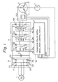
- Figure 1 shows a block circuit diagram for PWM control of a conventional synchronous motor using permanent magnets.
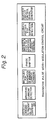
- Figure 2 shows an outline of functions of the transistor PWM control circuit in the apparatus of Fig. 1.
- reference numeral 1 denotes a three-phase power source, 2 a rectification circuit, 4 a transistor inverter, 5 a transistor PWM control circuit, 6 a synchronous motor using permanent magnets as a rotor, and 7 a rotor rotation detector, for example, a pulse encoder, for detecting a position and speed of the rotor of the synchronous motor 6.
- the transistor PWM control circuit 5 compares a velocity command value V o with a present velocity V (speed) detected by the rotor rotation detector 7, switches ON or OFF respective transistors 411 to 416 in the transistor inverter 4, and controls the speed by controlling the electric current through windings having U, V, and W phases in the synchronous motor 6.
- the transistor PWM control circuit mainly comprises a velocity command value to a present velocity value comparator, an armature current detector, a multiplier for generation of an armature current command value, a phase shifter, a differential amplitude filter for generation of an armature current command value, a feedback portion for saturation detection, and an inverter circuit control signal generator.
- K 1 ⁇ N ⁇ P ⁇ K 3 (V.sec/rad) is satisfied.
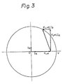
- K 2 1/2-P. Since, when the sum of K l w, i.e., the velocity voltage, and K 2 ⁇ L ⁇ l a , i.e., the voltage perpendicular to K 1 ⁇ , which is caused by the electric current l a and the inductance L, exceeds the circle V, the motor cannot be driven, thus a reactive current component I b is added and the voltage K 2 ⁇ L ⁇ l b is added.
- the output power of the motor can be increased.
- the application of the voltage K 2 ⁇ L ⁇ l b as above-mentioned is carried out by the above-mentioned saturation detection circuit 57, ROM 514, 515, D/A converter 521, 522, phase shift circuit 541, 542, 543.
- EP-A-0085891 A control method and a control apparatus according to the prior art portion of claim 1 and claim 2, respectively, are disclosed in EP-A-0085891.
- This prior art is intended to increase the rotation speed of a synchronous machine under the limitation that both the maximum terminal voltage and the magnetic field strength are constant.
- An object of the present invention is to provide a control method and apparatus for a synchronous motor, which is improved so that there is no reduction in the output power thereof, based on an idea whereby the reactive current component I b of the armature windings is limited so that the K 2 LI b does not exceed the counter-voltage constant K 1 .
- a control method for a synchronous motor which is a control method for controlling a synchronous motor using a permanent magnet field by the generation of a pulse width modulation signal comparing the difference between the command value of the armature winding current of the synchronous motor and the armature winding current value with the reference carrier wave, and by controlling the inverter by the pulse width modulation signal, wherein, when it is determined that the reactive component of the armature winding current is I b , the inductance of the armature winding is L, the counter electromotive force constant of the synchronous motor is K 1 , and the constant introduced from the pole number of the synchronous motor is K 2 , the value of the reactive component I b of the armature winding current is limited, the saturation degree of the differential signal between the current command signal defined by the peak value of the reference carrier wave and the armature winding current is detected, and the phase of the current command signal is changed from the phase position perpendicular to the armature wind
- a control apparatus for a synchronous motor provided with current detectors at the armature windings, the field of which is linked directly to a rotation detector, an inverter circuit for supplying electric power to the armature winding of the synchronous motor, and a pulse width modulation control circuit receiving a velocity command signal, the rotation detector output signal, and the armature winding current signal and generating a signal for controlling the inverter circuit;
- the pulse width modulation control circuit comprising a comparator which compares the velocity command signal with the signal from the rotation detector and generates an error signal, D/A converters for multiplication which generate a corrected each phase current command signal receiving a saturation degree signal representing the saturation degree of the differential value between the armature winding current command signal and the armature winding current signal, limiters for generating a limited current command signal which is limited by the predetermined condition receiving the corrected each phase current command signal from the D/A converter for multiplication, amplifier and filters for generating the armature winding current command
- a PWM control circuit in a control apparatus for a synchronous motor is shown in Figs. 5A and 5B.
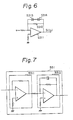
- An example of the constitution of a limiter in the apparatus of Figs. 5A and 5B is shown in Fig. 6.
- An example of the constitution of a differential amplifier and filter circuit in the apparatus of Figs. 5A and 5B is shown in Fig. 7.
- the relationship among the voltage/current of the synchronous motor in the apparatus of Figs. 5A and 5B is shown in a vector diagram of Fig. 4A.
- 513 is a signal process circuit
- 516 and 517 are read only memories (ROM) which memorize the values in U phase and W phase to be output in the phase perpendicular to the field main magnetic flux
- 514 and 515 are ROM's which memorize the values (U+90°) and (W+90°) proceeding by 90 degrees in phase to the ROM's 516 and 517, respectively
- 57 is a saturation detection circuit
- 511 is a differential amplifier wherein the difference between a voltage V o showing a velocity command and a voltage V (SPEED) showing a present velocity from the signal process circuit 513 is amplified and output.
- 512 is a filter, the frequency response of which is low gain in the high frequency and high gain in the low frequency, in which the peak voltage is clamped by a Zener diode.
- D/A converters are multiplying digital-to-analog (D/A) converters in which the voltage generated by the difference between the velocity command V o supplied from the filter 512 and the present velocity V (SPEED) is multiplied by the command values of the U phase and W phase output from the ROM's 516 and 517, and phase current commands A(I,) and A(l t ) of the U phase and the W phase, respectively, are made.
- D/A digital-to-analog
- 521 and 522 are multiplying D/A converters which output corrected phase current commands (B(l r ) and B(l t ) of the U phase and the W phase by the multiplied products of the output of the saturation detection circuit and outputs of ROM's 514 and 515, respectively
- 526 is an adder in which the phase current command A(I,) is added to AUt) and the current command A(l s ) having a phase difference of 120 degrees from the U phase and the W phase, is made
- 525 is an adder in which a correct phase current command (B(l s ) of the V phase is made from the outputs of the multiplying D/A converters 521 and 522.
- 581 and 582 are detectors detecting currents I(U) and I(W) which pass through the U phase and W phase armature windings of the synchronous motor 6, 583 is an adder in which the V phase current Is is calculated from the summation of the U phase current I r and the W phase current I t detected by the U phase current detector 581 and the W phase current detector 582, respectively.
- phase shift circuits in which the correct phase current command B(l r ), B(l s ) and B(l t ) of the respective U phase, V phase, and W phase, are added to the respective phase current command A(l r ), A(l s ) and A(l t ) and each phase is advanced, 551, 552, and 553 are circuits for supplying the current command voltages to be applied to the U phase, V phase, and W phase, and have the same constitution but receiving different input signals.
- 551 comprises a differential amplifier 5511 in which the difference between the output of the U phase, phase shift circuit 541 and the present U phase detection current l r is amplified, and a low pass filter circuit 5512 for passing only the frequency component in a reference carrier wave of the output of differential amplifier 5511.
- 552 and 553 receive the outputs of the V phase phase shift circuit 542 and the W phase phase shift circuit 543, respectively, and receive the present current values l s and l t , respectively, the other is the same as the circuit 551.
- 56 is a circuit comprising a PWM signal process circuit and a transistor base drive amplifier, in which the signals from the above-mentioned circuits 551, 552, and 553 are compared with the reference carrier wave V (REF), and PWM signals P, to P 6 , which turn ON or OFF each transistor 411 to 416 in a transistor inverter 4, are supplied.
- REF reference carrier wave
- a saturation detection circuit 57 receives the outputs of the circuits 551, 552, and 553. When the peak voltage of the outputs approaches the saturation voltage determined by the peak voltage of the reference carrier wave V (REF), a saturation signal V (SAT) is output corresponding to the saturation degree, and the output is supplied to the D/A converters 521 and 522.
- V (REF) peak voltage of the reference carrier wave
- the operation of the circuit of Figs. 5A and 5B is explained as follows.
- the signal process circuit 513 supplies the address of the ROM's 516, 517, 514 and 515 corresponding to the present velocity signal V (SPEED) and the present rotor position POS (U) an POS (W).
- the differential amplifier 511 receives the velocity command V o and supplies the voltage difference between the voltage of the present velocity signal V (SPEED) and the voltage of the velocity command V o , through the filter 512, as an error signal V (ERR).
- the D/A converters 523 and 524 for multiplication in the fourth quadrant and the adder 526 supply the U phase current command A(ir), the W phase current command A(l t ), and the V phase current command A(l s ), respectively.
- the ROM's 514 and 515 supply the U phase command value and W phase command value which precede the output command from the ROM's 516 and 517 by 90 degrees in phase.
- the command values and the saturation signal V (SAT) from the above-mentioned saturation detection circuit 57 are multiplied by the multiplying DA converters 521 and 522.
- the multiplied signals are supplied as the U phase correct phase current command (B(I,) and the W phase correct phase current command B(l t ).
- the adder 525 the summation of the U phase correct phase current command B(I, and the w phase correct phase current command B(l t ) is calculated and supplied as the V phase correct phase current command B(I.).
- phase current commands A(l r ), A(l s ), and A(l t ) and the each correct phase current commands B(l r ), B(l s ), and B(l t ) are supplied to the phase shift circuits 541, 542, and 543, respectively.
- the phase shift circuits 541, 542, and 543 have the same constitution and each phase shift circuit comprises an adder and an inversion amplifier.
- the U phase current command A(I,) is added to the U phase correct phase current command B(l r ) by the adder. Then, the added command is inverted by the inversion amplifier and the corrected U phase phase current command C(I,) in response to the saturation degree is obtained.
- the V phase corrected phase current command C(I.) and the W phase corrected phase current command C(l t ) are made by the same process as the U phase.
- the phase current commands C(I,), C(l s ) and C(l t ) corrected by the saturation degree are applied to the circuits 551, 552, and 553. In the circuits, the differences between the applied commands and the present phase currents I r .
- I., and l t passing each phase, detected from the U phase detector 581 and the W phase current detector 582 and the adder 583, are amplified, filtered, and supplied to the PWM signal process circuit 56 which is a source of an inverter circuit control signal, as voltages V(U), V(V) and V(W) corresponding to each phase command current value.
- the PWM signal process circuit 56 supplies PWM signals P 1 to P 6 , turns ON or OFF transistor inverters 411 to 416, and drives the synchronous motor 6 by a leading phase in response to the saturation degree.
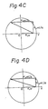
- the reactive component I b of the armature current is limited, so that the summation of the vectors Kw, K 2 ⁇ L ⁇ l a , and K 2 ⁇ L ⁇ l b , which are the voltage components of the armature of the synchronous motor, does not exceed the center line of the circle showing the peak value V of the supplying voltage perpendicular to the vector K 1 ⁇ .
- the value of I b is limited so that the multiplied product of K 2 , L, and I b does not exceed K l .
- limiters 531, 532, and 533 are further provided.
- the limiter 531 is connected between the output terminal of the D/A conveter 521 and the input terminal of the phase shift circuit 541.
- the limiter 532 is connected between the output terminal of the adder 525 and the input terminal of the phase shift circuit 542 and the limiter 533 is connected between the output terminal of the D/A converter 522 and the input terminal of the phase shift circuit 543.
- FIG. 6 An example of the constitution of the above-mentioned limiter circuit 531 is shown in Fig. 6.
- the circuit is a known circuit in which Zener diodes 5313 and 5314 are used in a feedback circuit of an operational amplifier 5311.
- the correct phase current commands B(l r ), B(l s ), and B(l t ) applied to the phase shift circuit are limited to less than a predetermined value, and the reactive current component I b of the armature of the synchronous motor is also limited, so that as shown in Figs. 4B, 4C and 4D, the resultant vector by the vector K 1 ⁇ , K 2 ⁇ L ⁇ l a , and K 2 ⁇ L ⁇ l b does not enter into the left half portion of the circle in Fig. 8.
- K 1 ⁇ is a multiplied product of the counter-voltage constant K 1 and the angular velocity w and represents a velocity voltage.
- K 2 ⁇ L ⁇ l a is a multiplied product of the constant K 2 corresponding to the pole number, the angular velocity w, the inductance L of one phase of the armature winding, and the effective current component l a in the armature, and the product is a voltage component perpendicular to the velocity voltage.
- the synchronous motor to which control method and apparatus according to the present invention is applied is for example, used for a synchronous motor for a servo motor which drives a numerical control machine tool. Further; for example, the synchronous motor is used for. driving an extrusion molding machine.
Landscapes
- Engineering & Computer Science (AREA)
- Power Engineering (AREA)
- Control Of Ac Motors In General (AREA)
- Inverter Devices (AREA)
Abstract
Claims (3)
la limitation par la condition prédéterminée dans les moyens formant limiteur (531 à 533) étant réalisée par la limitation de la composante réactive Ib du courant dans le bobinage d'induit de telle manière que le produit de K2, L et Ib ne dépasse pas la valeur de K1, où lb est la composante réactive du courant dans le bobinage d'induit, L est l'inductance du bobinage d'induit, K2 est la constante déterminée à partir du nombre de pôles du moteur, et K1 est la constante de force électromotrice du moteur.
Applications Claiming Priority (2)
| Application Number | Priority Date | Filing Date | Title |
|---|---|---|---|
| JP59141362A JPS6122795A (ja) | 1984-07-10 | 1984-07-10 | 同期電動機の制御方法 |
| JP141362/84 | 1984-07-10 |
Publications (3)
| Publication Number | Publication Date |
|---|---|
| EP0187867A1 EP0187867A1 (fr) | 1986-07-23 |
| EP0187867A4 EP0187867A4 (fr) | 1987-10-20 |
| EP0187867B1 true EP0187867B1 (fr) | 1991-01-23 |
Family
ID=15290213
Family Applications (1)
| Application Number | Title | Priority Date | Filing Date |
|---|---|---|---|
| EP85903390A Expired - Lifetime EP0187867B1 (fr) | 1984-07-10 | 1985-07-10 | Procede et dispositif de commande d'un moteur synchrone |
Country Status (6)
| Country | Link |
|---|---|
| US (1) | US4703246A (fr) |
| EP (1) | EP0187867B1 (fr) |
| JP (1) | JPS6122795A (fr) |
| KR (1) | KR900001792B1 (fr) |
| DE (1) | DE3581525D1 (fr) |
| WO (1) | WO1986000766A1 (fr) |
Families Citing this family (8)
| Publication number | Priority date | Publication date | Assignee | Title |
|---|---|---|---|---|
| US5231341A (en) * | 1991-09-18 | 1993-07-27 | Samsung Electronics Co., Ltd. | Limiter circuit of servo motor control apparatus |
| KR950004836B1 (ko) * | 1991-10-21 | 1995-05-13 | 삼성전자 주식회사 | 교류 전동기의 상전압 측정장치 및 그 측정방법 |
| US5652495A (en) * | 1994-05-25 | 1997-07-29 | Matsushita Electric Industrial Co., Ltd. | Controller for permanent magnet synchronous motor |
| US5780990A (en) * | 1997-03-06 | 1998-07-14 | Weber; Harold J. | Parasynchronous induction motor control method and apparatus |
| FI112735B (fi) * | 1997-12-03 | 2003-12-31 | Kone Corp | Menetelmä synkronisen kestomagneettimoottorin ohjaamiseksi |
| JP2003037990A (ja) * | 2001-07-24 | 2003-02-07 | Hitachi Ltd | モータ制御装置 |
| US7211973B1 (en) | 2005-01-07 | 2007-05-01 | Marvell Asia Pte, Ltd. | System and process for utilizing back electromotive force in disk drives |
| KR101237604B1 (ko) * | 2011-09-02 | 2013-02-26 | 한국기술교육대학교 산학협력단 | 자이로 센서 구동 장치 및 그 방법 |
Citations (1)
| Publication number | Priority date | Publication date | Assignee | Title |
|---|---|---|---|---|
| EP0085891A1 (fr) * | 1982-01-26 | 1983-08-17 | LABORATORI BALDACCI Spa | Composition pour le nettoyage et l'hygiène dentaire |
Family Cites Families (13)
| Publication number | Priority date | Publication date | Assignee | Title |
|---|---|---|---|---|
| US3662247A (en) * | 1970-10-01 | 1972-05-09 | Reliance Electric Co | Pulse width modulated inverter adaptive logic |
| US3851234A (en) * | 1973-05-09 | 1974-11-26 | Gen Electric | Control system for obtaining and using the optimum speed torque characteristic for a squirrel cage induction motor which guarantees a non-saturating magnetizing current |
| US3971972A (en) * | 1975-03-14 | 1976-07-27 | Allis-Chalmers Corporation | Transistor inverter motor drive having voltage boost at low speeds |
| JPS5396423A (en) * | 1977-02-01 | 1978-08-23 | Mitsubishi Electric Corp | Control system for induction motor |
| US4330741A (en) * | 1979-06-20 | 1982-05-18 | Hitachi, Ltd. | Electric control apparatus of induction motor |
| JPS576584A (en) * | 1980-06-12 | 1982-01-13 | Toshiba Mach Co Ltd | Controller for drive of synchronous motor |
| DE3272250D1 (en) * | 1981-03-31 | 1986-09-04 | Fanuc Ltd | Method of controlling an ac motor and device thereof |
| US4361791A (en) * | 1981-05-12 | 1982-11-30 | General Electric Company | Apparatus for controlling a PWM inverter-permanent magnet synchronous motor drive |
| JPS57206292A (en) * | 1981-06-10 | 1982-12-17 | Fuji Electric Co Ltd | Controlling device for variable speed motor |
| US4445080A (en) * | 1981-11-25 | 1984-04-24 | The Charles Stark Draper Laboratory, Inc. | System for indirectly sensing flux in an induction motor |
| JPS5893492A (ja) * | 1981-11-26 | 1983-06-03 | Fuji Electric Co Ltd | 同期電動機の制御方法 |
| JPS58157384A (ja) * | 1982-03-12 | 1983-09-19 | Fanuc Ltd | 交流モ−タの駆動方式 |
| JPS58205221A (ja) * | 1982-05-26 | 1983-11-30 | Toshiba Corp | 電力変換装置の電流制御方法 |
-
1984
- 1984-07-10 JP JP59141362A patent/JPS6122795A/ja active Pending
-
1985
- 1985-07-10 WO PCT/JP1985/000388 patent/WO1986000766A1/fr not_active Ceased
- 1985-07-10 KR KR1019860700139A patent/KR900001792B1/ko not_active Expired
- 1985-07-10 DE DE8585903390T patent/DE3581525D1/de not_active Expired - Lifetime
- 1985-07-10 US US06/842,706 patent/US4703246A/en not_active Expired - Lifetime
- 1985-07-10 EP EP85903390A patent/EP0187867B1/fr not_active Expired - Lifetime
Patent Citations (1)
| Publication number | Priority date | Publication date | Assignee | Title |
|---|---|---|---|---|
| EP0085891A1 (fr) * | 1982-01-26 | 1983-08-17 | LABORATORI BALDACCI Spa | Composition pour le nettoyage et l'hygiène dentaire |
Also Published As
| Publication number | Publication date |
|---|---|
| DE3581525D1 (de) | 1991-02-28 |
| KR900001792B1 (ko) | 1990-03-24 |
| JPS6122795A (ja) | 1986-01-31 |
| EP0187867A1 (fr) | 1986-07-23 |
| EP0187867A4 (fr) | 1987-10-20 |
| KR860700321A (ko) | 1986-08-01 |
| US4703246A (en) | 1987-10-27 |
| WO1986000766A1 (fr) | 1986-01-30 |
Similar Documents
| Publication | Publication Date | Title |
|---|---|---|
| US5701065A (en) | Method and apparatus for controlling synchronous motor | |
| US4490661A (en) | Control system for synchronous brushless motors utilizing torque angle control | |
| US5656911A (en) | Circuit for driving permanent-magnet synchronous motor using proportional controller | |
| US4364109A (en) | Control device of inverters | |
| US4658190A (en) | Reduced ripple drive circuit for a brushless motor | |
| US20060145639A1 (en) | Brushless DC motor system and method of controlling the same | |
| US4680525A (en) | Induction motor driving system | |
| JPS62100194A (ja) | サ−ボモ−タにおけるトルク制御方式 | |
| EP0187867B1 (fr) | Procede et dispositif de commande d'un moteur synchrone | |
| US4703245A (en) | Method and apparatus for controlling permanent magnet synchronous motor by using pulse width modulation | |
| US4467262A (en) | Polyphase motor drive system with balanced modulation | |
| EP0289362A2 (fr) | Systèmes de régulation pour moteurs sans balais | |
| US4306182A (en) | Polyphase motor drive system with balanced modulation | |
| US5449986A (en) | Linearizing decoupling controller for electric motors | |
| FI94301C (fi) | Moottorin ohjauslaite | |
| US4074174A (en) | Controlling apparatus for asynchronous motors with wound rotor | |
| CA1041604A (fr) | Commande electronique de charges connectees en etoile | |
| JPH0378491A (ja) | 駆動電動機を備えた駆動装置 | |
| EP0142563A1 (fr) | Systeme de commande d'un moteur synchrone | |
| US4295084A (en) | Control apparatus of synchronous motor having thyristor converter | |
| US5543700A (en) | Driver circuit and a driving method for a variable-reluctance motor | |
| WO2023026273A1 (fr) | Onduleur à enroulements ouverts optimal pour commander des moteurs à courant alternatif triphasé | |
| US5268628A (en) | Phase voltage measuring device of an AC motor and a measuring method thereof | |
| EP0150472B1 (fr) | Système de commande d'un moteur à induction pour améliorer la réponse transitoire d'excitation par angle commandé | |
| US5852356A (en) | DC/AC inverter for power supply to an electrical motor for the traction of a vehicle |
Legal Events
| Date | Code | Title | Description |
|---|---|---|---|
| PUAI | Public reference made under article 153(3) epc to a published international application that has entered the european phase |
Free format text: ORIGINAL CODE: 0009012 |
|
| 17P | Request for examination filed |
Effective date: 19860310 |
|
| AK | Designated contracting states |
Kind code of ref document: A1 Designated state(s): DE FR GB |
|
| A4 | Supplementary search report drawn up and despatched |
Effective date: 19871020 |
|
| 17Q | First examination report despatched |
Effective date: 19890928 |
|
| GRAA | (expected) grant |
Free format text: ORIGINAL CODE: 0009210 |
|
| AK | Designated contracting states |
Kind code of ref document: B1 Designated state(s): DE FR GB |
|
| REF | Corresponds to: |
Ref document number: 3581525 Country of ref document: DE Date of ref document: 19910228 |
|
| ET | Fr: translation filed | ||
| PGFP | Annual fee paid to national office [announced via postgrant information from national office to epo] |
Ref country code: GB Payment date: 19910701 Year of fee payment: 7 |
|
| PGFP | Annual fee paid to national office [announced via postgrant information from national office to epo] |
Ref country code: FR Payment date: 19910717 Year of fee payment: 7 |
|
| PLBE | No opposition filed within time limit |
Free format text: ORIGINAL CODE: 0009261 |
|
| STAA | Information on the status of an ep patent application or granted ep patent |
Free format text: STATUS: NO OPPOSITION FILED WITHIN TIME LIMIT |
|
| 26N | No opposition filed | ||
| PG25 | Lapsed in a contracting state [announced via postgrant information from national office to epo] |
Ref country code: GB Effective date: 19920710 |
|
| GBPC | Gb: european patent ceased through non-payment of renewal fee |
Effective date: 19920710 |
|
| PG25 | Lapsed in a contracting state [announced via postgrant information from national office to epo] |
Ref country code: FR Effective date: 19930331 |
|
| REG | Reference to a national code |
Ref country code: FR Ref legal event code: ST |
|
| PGFP | Annual fee paid to national office [announced via postgrant information from national office to epo] |
Ref country code: DE Payment date: 19980720 Year of fee payment: 14 |
|
| PG25 | Lapsed in a contracting state [announced via postgrant information from national office to epo] |
Ref country code: DE Free format text: LAPSE BECAUSE OF NON-PAYMENT OF DUE FEES Effective date: 20000503 |