EP0187876A1 - Système d'installation pour ascenseur - Google Patents
Système d'installation pour ascenseur Download PDFInfo
- Publication number
- EP0187876A1 EP0187876A1 EP85100265A EP85100265A EP0187876A1 EP 0187876 A1 EP0187876 A1 EP 0187876A1 EP 85100265 A EP85100265 A EP 85100265A EP 85100265 A EP85100265 A EP 85100265A EP 0187876 A1 EP0187876 A1 EP 0187876A1
- Authority
- EP
- European Patent Office
- Prior art keywords
- controller
- control
- data
- transmitted
- car
- Prior art date
- Legal status (The legal status is an assumption and is not a legal conclusion. Google has not performed a legal analysis and makes no representation as to the accuracy of the status listed.)
- Granted
Links
Images
Classifications
-
- B—PERFORMING OPERATIONS; TRANSPORTING
- B66—HOISTING; LIFTING; HAULING
- B66B—ELEVATORS; ESCALATORS OR MOVING WALKWAYS
- B66B1/00—Control systems of elevators in general
- B66B1/34—Details, e.g. call counting devices, data transmission from car to control system, devices giving information to the control system
- B66B1/46—Adaptations of switches or switchgear
- B66B1/468—Call registering systems
Definitions
- the invention relates to an installation system for an elevator system with at least one hanging cable for establishing the necessary connections between a car and associated control and with permanently installed connecting lines between the outside call panels in the individual floors and the control.
- the previous installation systems require complex cable installation in the elevator shaft, on the one hand to include the various functional elements, e.g. to supply the door drives, the various operating buttons, the signal and display elements etc. and, on the other hand, to transmit the driving requests made by the elevator users to the landing call panels located on the floors for control purposes and to acknowledge them from there.
- Each external call panel and each door are individually connected to the control in the machine room by their own multi-core cables, and the car is also connected to the control system by several multi-core suspension cables.
- Control and installation therefore have to be redesigned or adapted to the special features of the system in question, which is not only time-consuming and ultimately expensive during the design phase, but also often leads to unexpected errors in the manufacture, testing and commissioning of the system.
- the shaft installation cannot be prefabricated as standard in the factory, since it must be adapted to the special features of the system in question.
- the invention is based on the object, with due consideration of the hardware expenditure in the floors and in the control system, the number of inputs and outputs of the control system and thus the number of line wires, regardless of the special features to keep the elevator system constant and thereby create the possibility of inexpensive series production of the shaft installation and a corresponding simplification of the laying and fastening of this installation in the shaft.
- control is designed using at least one microprocessor in such a way that clock signals, bit-parallel transferable address signals and serial transferable data signals can be generated for the external call panels and bit-parallel transferred data signals can be evaluated by the external call panels are that each external call tableau has a floor module that is identical for all floors, to which the clock signals, the address signals transmitted in bit parallel and the serial data signals can be fed from the controller and from which the data signals transmitted in bit parallel can be transmitted to the controller, and that the permanently installed connection lines between all outside call panels and the control are combined into a single, multi-core line.
- the directly made landing calls, special functions such as fire brigade, special trip or the like, and data that arise on the doors assigned to the panels can be transmitted to the control from the outside call panels.
- control connection (port) of the control via which the six address lines are operated, via which the required address information is transmitted bit-parallel to the landing call tableaus, also serves to address the car, with which the number of inputs and outputs of the control is greatly reduced.
- control costs can be significantly reduced.
- control is designed in such a way that the data relating to the car are transmitted by the control are output via the same control connection as the data for each of the outer panels, that is to say if the data line for the car branches off from the data line for the outer panels via which the data is transmitted serially.
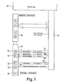
- FIG. 1 shows an installation system according to the invention with a controller 10 containing at least one microprocessor, which with the external call panels 12 located on the individual floors, of which only two are shown for the sake of simplicity, via a single, in the exemplary embodiment 16-wire commercially available flat cable 14 is connected.
- Each of the outside call panels 12 has an up call button 16 with an associated feedback lamp 18 and a down call button 20 with an associated feedback lamp 22.
- the sixteen wires of the flat cable 14 are fanned out in FIG. 1 for the landing call tableau 12 assigned to the lowest floor, and it can be seen that a six-wire address bus 24 for bit-parallel address transmission, a single-wire clock line 26, a single-wire data line 28 for serial data transmission from the controller 10 to the external call panel 12, a six-wire data bus 30 for bit-parallel data transmission from the external panel 12 to the controller 10 and a two-wire power supply 32 for the external panel are provided.
- a control button 36 drawn in dashed lines in panel 12 shows the possibility of transmitting, in addition to the normal external calls "up” and “down”, further special signals such as "fire brigade", "special trip” or "door monitoring".
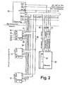
- FIG. 2 The detailed block diagram according to FIG. 2, in which the outer panels 12 for the bottom floor - stop 0, for the top floor - stop N and for the second highest floor - stop N -1 and which also shows a car 38 with its connections to the controller 10, shows that the six wires which form the address bus 24 simultaneously form the address bus 40 for the car and also that the single-wire data line 28 for serial data transmission is also connected to the car's interior call panel 42.
- a further single-core clock line 43 leads to the car 38.
- a further single-core data line 44 is available for the serial data transmission from the car 38 to the controller 10. It can be seen that the same address port of the controller 10 serves both the outside call panels 12 and the inside call panel 42.
- the * serially transmitted output data are transmitted from the same port of the controller 10 both to the outside call tableaus 12 and to the inside call tableau 42 of the car 38.
- this enables the hardware expenditure for the control to be reduced and, on the other hand, the number of lines for installation in the engine room can be kept very small.
- the lines described not only enable the exchange of information between the controller 10 and the landing call panels 12 on the main access side of the elevator installation, but also the exchange of information with other outside call panels on the through-loading side, not shown in FIG. 2, then clearly that the number of line connections required is actually reduced to a minimum in the installation system according to the invention.
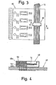
- each landing call panel 12 has a floor module that is identical for all floors.
- FIG. 3 shows a schematic plan view of such a module, in the form of a printed circuit or card 46 equipped with the corresponding components, in particular with integrated circuits.
- This card 46 can be designed in a conventional manner as a plug-in card and be inserted into a plug-in strip in order to produce the required external connections.
- the connections to the flat cable 14 are made by means of a clamping-cutting plug connector 48, which is shown in section in FIG. 4 and with the aid of which the electrical contact between the individual conductors or cores of the flat cable 14 on the one hand and the printed circuit traces of the card 46 on the other hand.
- the flat cable 14 is simply laid in the area of the connector 48 over the card 46, to which the necessary electrical connections are then made by the cutting tips 50 provided on the upper part 48a of the connector 48 through the line 14 are pressed into the associated receptacles 52 of the lower part 48b of the connector 48. It is understood that the card 46 and the associated terminal block (not shown) are arranged in a protective housing through which the line 14 is passed.
- the individual floor modules or cards 46 differ only in that the memories of the floor modules used for address evaluation are each set to a different address.
- So-called DIL switches which can be coded according to a predetermined plan when installing the modules, have proven particularly useful as memories.
- the data bus 30 normally only two wires are required to transmit the external calls from the individual external call panels 12 to the controller 10.
- three wires are still available for the transmission of special signals, for example for the transmission of the output signals of a door monitoring system.
- the possibility of transmitting at least three special signals is indicated in FIG. 2 by three small input arrows on each of the outside call panels 12.
Landscapes
- Engineering & Computer Science (AREA)
- Automation & Control Theory (AREA)
- Computer Networks & Wireless Communication (AREA)
- Indicating And Signalling Devices For Elevators (AREA)
- Elevator Control (AREA)
- Selective Calling Equipment (AREA)
Priority Applications (3)
| Application Number | Priority Date | Filing Date | Title |
|---|---|---|---|
| AT85100265T ATE35667T1 (de) | 1985-01-12 | 1985-01-12 | Installationssystem fuer eine aufzugsanlage. |
| DE8585100265T DE3563730D1 (en) | 1985-01-12 | 1985-01-12 | Installation system for a lift construction |
| EP85100265A EP0187876B1 (fr) | 1985-01-12 | 1985-01-12 | Système d'installation pour ascenseur |
Applications Claiming Priority (1)
| Application Number | Priority Date | Filing Date | Title |
|---|---|---|---|
| EP85100265A EP0187876B1 (fr) | 1985-01-12 | 1985-01-12 | Système d'installation pour ascenseur |
Publications (2)
| Publication Number | Publication Date |
|---|---|
| EP0187876A1 true EP0187876A1 (fr) | 1986-07-23 |
| EP0187876B1 EP0187876B1 (fr) | 1988-07-13 |
Family
ID=8193224
Family Applications (1)
| Application Number | Title | Priority Date | Filing Date |
|---|---|---|---|
| EP85100265A Expired EP0187876B1 (fr) | 1985-01-12 | 1985-01-12 | Système d'installation pour ascenseur |
Country Status (3)
| Country | Link |
|---|---|
| EP (1) | EP0187876B1 (fr) |
| AT (1) | ATE35667T1 (fr) |
| DE (1) | DE3563730D1 (fr) |
Cited By (10)
| Publication number | Priority date | Publication date | Assignee | Title |
|---|---|---|---|---|
| FR2617149A1 (fr) * | 1987-06-25 | 1988-12-30 | Sofima Financ | Dispositif de commande de monte-charge non accompagnes |
| GB2227856A (en) * | 1989-02-02 | 1990-08-08 | Kone Elevator Gmbh | Procedure and apparatus for transmitting the call data obtained from the call buttons to the control system of an elevator |
| GB2225452B (en) * | 1988-09-20 | 1993-05-19 | Hitachi Ltd | Elevator control system |
| EP0780337B1 (fr) * | 1995-12-19 | 2003-10-15 | Otis Elevator Company | Système de contrôle pour transporteur de passagers avec entrées/sorties décentralisées |
| EP1518812A1 (fr) * | 2003-09-29 | 2005-03-30 | Dätwyler Ag Schweizerische Kabel-, Gummi- Und Kunststoffwerke | Câblage d'une gaine d'ascenseur |
| CN101670964B (zh) * | 2008-09-11 | 2011-06-15 | 宁波经济技术开发区杰奇电梯配件有限公司 | 电梯轿厢操纵板 |
| CN101670963B (zh) * | 2008-09-11 | 2011-08-24 | 宁波经济技术开发区杰奇电梯配件有限公司 | 电梯厅外召唤控制板 |
| RU177633U1 (ru) * | 2016-12-12 | 2018-03-02 | Общество с ограниченной ответственностью "Электронные и программные системы" (ООО "ЭЛИПС") | Сигнальный блок устройства управления лифтом |
| RU2654257C1 (ru) * | 2017-03-13 | 2018-05-17 | Андрей Валентинович Гневашев | Контроллер устройства управления лифтом |
| CN114030959A (zh) * | 2021-11-12 | 2022-02-11 | 日立楼宇技术(广州)有限公司 | 一种电梯串行通信线缆、外呼地址设置系统及电梯 |
Families Citing this family (1)
| Publication number | Priority date | Publication date | Assignee | Title |
|---|---|---|---|---|
| RU174322U1 (ru) * | 2016-12-12 | 2017-10-11 | Общество с ограниченной ответственностью "Электронные и программные системы" (ООО "ЭЛИПС") | Устройство управления лифтом |
Citations (4)
| Publication number | Priority date | Publication date | Assignee | Title |
|---|---|---|---|---|
| US3807531A (en) * | 1973-03-12 | 1974-04-30 | Westinghouse Electric Corp | Elevator system |
| US3841443A (en) * | 1973-09-13 | 1974-10-15 | Westinghouse Electric Corp | Elevator system |
| US4042067A (en) * | 1975-05-16 | 1977-08-16 | Westinghouse Electric Corporation | Elevator system |
| EP0100866A1 (fr) * | 1982-08-18 | 1984-02-22 | Inventio Ag | Circuit de transmission de données à matrice pour installations d'ascenseur |
-
1985
- 1985-01-12 AT AT85100265T patent/ATE35667T1/de not_active IP Right Cessation
- 1985-01-12 EP EP85100265A patent/EP0187876B1/fr not_active Expired
- 1985-01-12 DE DE8585100265T patent/DE3563730D1/de not_active Expired
Patent Citations (4)
| Publication number | Priority date | Publication date | Assignee | Title |
|---|---|---|---|---|
| US3807531A (en) * | 1973-03-12 | 1974-04-30 | Westinghouse Electric Corp | Elevator system |
| US3841443A (en) * | 1973-09-13 | 1974-10-15 | Westinghouse Electric Corp | Elevator system |
| US4042067A (en) * | 1975-05-16 | 1977-08-16 | Westinghouse Electric Corporation | Elevator system |
| EP0100866A1 (fr) * | 1982-08-18 | 1984-02-22 | Inventio Ag | Circuit de transmission de données à matrice pour installations d'ascenseur |
Cited By (13)
| Publication number | Priority date | Publication date | Assignee | Title |
|---|---|---|---|---|
| FR2617149A1 (fr) * | 1987-06-25 | 1988-12-30 | Sofima Financ | Dispositif de commande de monte-charge non accompagnes |
| GB2225452B (en) * | 1988-09-20 | 1993-05-19 | Hitachi Ltd | Elevator control system |
| GB2227856A (en) * | 1989-02-02 | 1990-08-08 | Kone Elevator Gmbh | Procedure and apparatus for transmitting the call data obtained from the call buttons to the control system of an elevator |
| GB2227856B (en) * | 1989-02-02 | 1993-07-28 | Kone Elevator Gmbh | Procedure and apparatus for transmitting the call data obtained from the call buttons to the control system of an elevator |
| EP0780337B1 (fr) * | 1995-12-19 | 2003-10-15 | Otis Elevator Company | Système de contrôle pour transporteur de passagers avec entrées/sorties décentralisées |
| WO2005037703A1 (fr) * | 2003-09-29 | 2005-04-28 | Dätwyler Ag Schweizerische Kabel-, Gummi- Und Kunststoffwerke | Cablage de cage d'ascenseur |
| EP1518812A1 (fr) * | 2003-09-29 | 2005-03-30 | Dätwyler Ag Schweizerische Kabel-, Gummi- Und Kunststoffwerke | Câblage d'une gaine d'ascenseur |
| CN101670964B (zh) * | 2008-09-11 | 2011-06-15 | 宁波经济技术开发区杰奇电梯配件有限公司 | 电梯轿厢操纵板 |
| CN101670963B (zh) * | 2008-09-11 | 2011-08-24 | 宁波经济技术开发区杰奇电梯配件有限公司 | 电梯厅外召唤控制板 |
| RU177633U1 (ru) * | 2016-12-12 | 2018-03-02 | Общество с ограниченной ответственностью "Электронные и программные системы" (ООО "ЭЛИПС") | Сигнальный блок устройства управления лифтом |
| RU2654257C1 (ru) * | 2017-03-13 | 2018-05-17 | Андрей Валентинович Гневашев | Контроллер устройства управления лифтом |
| CN114030959A (zh) * | 2021-11-12 | 2022-02-11 | 日立楼宇技术(广州)有限公司 | 一种电梯串行通信线缆、外呼地址设置系统及电梯 |
| CN114030959B (zh) * | 2021-11-12 | 2023-10-31 | 日立楼宇技术(广州)有限公司 | 一种电梯串行通信线缆、外呼地址设置系统及电梯 |
Also Published As
| Publication number | Publication date |
|---|---|
| DE3563730D1 (en) | 1988-08-18 |
| EP0187876B1 (fr) | 1988-07-13 |
| ATE35667T1 (de) | 1988-07-15 |
Similar Documents
| Publication | Publication Date | Title |
|---|---|---|
| EP1174781B1 (fr) | Appareil de transmission de signal | |
| EP0452658B1 (fr) | Unité de connexion pour installations domestiques | |
| DE4440102C1 (de) | Modulare Steuerungsanlage mit integriertem Feldbusanschluß | |
| DE3740568C2 (fr) | ||
| DE19535277C1 (de) | Baugruppe eines Automatisierungsgeräts | |
| EP0275992A2 (fr) | Parc machine avec plusieurs mobiles | |
| DE3137388C2 (fr) | ||
| WO1999054632A1 (fr) | Systeme electrofluidique modulaire | |
| EP0187876B1 (fr) | Système d'installation pour ascenseur | |
| DE19507407B4 (de) | Einrichtung zur Betätigung und Überwachung von Rauch- und Wärmeabzugsöffnungen | |
| DE19541154A1 (de) | Aktor/Sensor Kombination für die Gebäudesystemtechnik | |
| DE19743974B4 (de) | Schaltschrank | |
| CH629059A5 (de) | Mit anschlussorganen fuer anschlussdraehte versehene elektrische anschlussplatte. | |
| EP1576867B1 (fr) | Carte orientee processus a integration et extension modulaire d'automate programmable | |
| DE29704307U1 (de) | Dezentrales Modul zur Zusammenführung und Verteilung von Signalleitungen | |
| EP0740082A1 (fr) | Dispositif électrique modulaire pour un assemblage de bloc de vannes | |
| DE69527902T2 (de) | System und vorrichtung zur vorautomatisierung der schaltanlagen eines gebäudes | |
| EP0792078B1 (fr) | Système d'interface pour capteurs-actionneurs | |
| DE19647823B4 (de) | Steuerungs- und Überwachungsvorrichtung für eine Rauch- und Wärmeabzugsanlage | |
| DE19813389A1 (de) | Sicherheitsgerichtete Ansteuerschaltung | |
| EP0984168B1 (fr) | Arrangement de soupapes avec au moins une unité composée de plusieurs soupapes à actionnement électrique | |
| EP0891008A1 (fr) | Système de distribution d'énergie | |
| DE4013815C2 (de) | Steuerschaltung für Maschinen | |
| EP0585548A1 (fr) | Station de terrain pour un système de bus sériel commandé par ordinateur | |
| EP0855816A2 (fr) | Méthode et appareil pour la transmission de données d'un bus de secteur dans le domain de la technique de réseau domestiques par un interface de bus pour les modules d'application de la technique de systèmes domestiques |
Legal Events
| Date | Code | Title | Description |
|---|---|---|---|
| PUAI | Public reference made under article 153(3) epc to a published international application that has entered the european phase |
Free format text: ORIGINAL CODE: 0009012 |
|
| AK | Designated contracting states |
Kind code of ref document: A1 Designated state(s): AT BE CH DE FR GB LI NL |
|
| 17P | Request for examination filed |
Effective date: 19861230 |
|
| 17Q | First examination report despatched |
Effective date: 19870909 |
|
| GRAA | (expected) grant |
Free format text: ORIGINAL CODE: 0009210 |
|
| AK | Designated contracting states |
Kind code of ref document: B1 Designated state(s): AT BE CH DE FR GB LI NL |
|
| REF | Corresponds to: |
Ref document number: 35667 Country of ref document: AT Date of ref document: 19880715 Kind code of ref document: T |
|
| REF | Corresponds to: |
Ref document number: 3563730 Country of ref document: DE Date of ref document: 19880818 |
|
| GBT | Gb: translation of ep patent filed (gb section 77(6)(a)/1977) | ||
| ET | Fr: translation filed | ||
| PLBE | No opposition filed within time limit |
Free format text: ORIGINAL CODE: 0009261 |
|
| STAA | Information on the status of an ep patent application or granted ep patent |
Free format text: STATUS: NO OPPOSITION FILED WITHIN TIME LIMIT |
|
| 26N | No opposition filed | ||
| PGFP | Annual fee paid to national office [announced via postgrant information from national office to epo] |
Ref country code: CH Payment date: 19930125 Year of fee payment: 9 |
|
| PGFP | Annual fee paid to national office [announced via postgrant information from national office to epo] |
Ref country code: NL Payment date: 19930131 Year of fee payment: 9 |
|
| PGFP | Annual fee paid to national office [announced via postgrant information from national office to epo] |
Ref country code: BE Payment date: 19930201 Year of fee payment: 9 |
|
| PG25 | Lapsed in a contracting state [announced via postgrant information from national office to epo] |
Ref country code: BE Effective date: 19940131 Ref country code: CH Effective date: 19940131 Ref country code: LI Effective date: 19940131 |
|
| BERE | Be: lapsed |
Owner name: THYSSEN-M.A.N. AUFZUGE G.M.B.H. Effective date: 19940131 |
|
| PG25 | Lapsed in a contracting state [announced via postgrant information from national office to epo] |
Ref country code: NL Effective date: 19940801 |
|
| NLV4 | Nl: lapsed or anulled due to non-payment of the annual fee | ||
| REG | Reference to a national code |
Ref country code: CH Ref legal event code: PL |
|
| PGFP | Annual fee paid to national office [announced via postgrant information from national office to epo] |
Ref country code: AT Payment date: 19990119 Year of fee payment: 15 |
|
| PGFP | Annual fee paid to national office [announced via postgrant information from national office to epo] |
Ref country code: FR Payment date: 19991230 Year of fee payment: 16 |
|
| PG25 | Lapsed in a contracting state [announced via postgrant information from national office to epo] |
Ref country code: AT Free format text: LAPSE BECAUSE OF NON-PAYMENT OF DUE FEES Effective date: 20000112 |
|
| PGFP | Annual fee paid to national office [announced via postgrant information from national office to epo] |
Ref country code: GB Payment date: 20000112 Year of fee payment: 16 |
|
| PGFP | Annual fee paid to national office [announced via postgrant information from national office to epo] |
Ref country code: DE Payment date: 20000223 Year of fee payment: 16 |
|
| PG25 | Lapsed in a contracting state [announced via postgrant information from national office to epo] |
Ref country code: GB Free format text: LAPSE BECAUSE OF NON-PAYMENT OF DUE FEES Effective date: 20010112 |
|
| GBPC | Gb: european patent ceased through non-payment of renewal fee |
Effective date: 20010112 |
|
| PG25 | Lapsed in a contracting state [announced via postgrant information from national office to epo] |
Ref country code: FR Free format text: LAPSE BECAUSE OF NON-PAYMENT OF DUE FEES Effective date: 20010928 |
|
| PG25 | Lapsed in a contracting state [announced via postgrant information from national office to epo] |
Ref country code: DE Free format text: LAPSE BECAUSE OF NON-PAYMENT OF DUE FEES Effective date: 20011101 |
|
| REG | Reference to a national code |
Ref country code: FR Ref legal event code: ST |