EP0187939A2 - Leitung zum Versorgen von elektrischer Energie mit reduzierten elektrodynamischen Kurzschluss- und Induktionswirkungen - Google Patents
Leitung zum Versorgen von elektrischer Energie mit reduzierten elektrodynamischen Kurzschluss- und Induktionswirkungen Download PDFInfo
- Publication number
- EP0187939A2 EP0187939A2 EP85115346A EP85115346A EP0187939A2 EP 0187939 A2 EP0187939 A2 EP 0187939A2 EP 85115346 A EP85115346 A EP 85115346A EP 85115346 A EP85115346 A EP 85115346A EP 0187939 A2 EP0187939 A2 EP 0187939A2
- Authority
- EP
- European Patent Office
- Prior art keywords
- duct
- conductors
- electric power
- supplying electric
- center
- Prior art date
- Legal status (The legal status is an assumption and is not a legal conclusion. Google has not performed a legal analysis and makes no representation as to the accuracy of the status listed.)
- Withdrawn
Links
- 230000005520 electrodynamics Effects 0.000 title description 4
- 230000000694 effects Effects 0.000 title description 2
- 239000004020 conductor Substances 0.000 claims abstract description 37
- 230000005484 gravity Effects 0.000 claims abstract description 7
- 230000007935 neutral effect Effects 0.000 claims abstract description 6
- 230000008878 coupling Effects 0.000 claims 1
- 238000010168 coupling process Methods 0.000 claims 1
- 238000005859 coupling reaction Methods 0.000 claims 1
- 230000003247 decreasing effect Effects 0.000 description 2
- 238000000034 method Methods 0.000 description 2
- 238000003466 welding Methods 0.000 description 2
- 239000012212 insulator Substances 0.000 description 1
- 239000002184 metal Substances 0.000 description 1
- 230000003071 parasitic effect Effects 0.000 description 1
Images
Classifications
-
- H—ELECTRICITY
- H02—GENERATION; CONVERSION OR DISTRIBUTION OF ELECTRIC POWER
- H02G—INSTALLATION OF ELECTRIC CABLES OR LINES, OR OF COMBINED OPTICAL AND ELECTRIC CABLES OR LINES
- H02G5/00—Installations of bus-bars
- H02G5/06—Totally-enclosed installations, e.g. in metal casings
Definitions
- the present invention relates to a duct for supplying electric power, having reduced electrodynamic short--circuit and inductance effects.
- the presently available ducts consist of a plurality of conductors or wires arranged in an adjoining relationship, in such a way as to provide a single duct supplied with several phases.
- Each conductor consists of sections which are so arranged as to oppose a maximum moment of inertia to the electromechanical stresses, and is supported by suitable strong insulators or bushings.
- suitable strong insulators or bushings On the other hand, frequently deformations of the conductors or breakages of the supporting bushings occurs, because of the electromechanical stresses, without considering the losses caused by the mutual inductance of the conductors.
- the main object of the present invention is to provide such a duct for supplying electric power which is effective to overcome the above mentioned drawback, that is to greatly reduce the electrodynamic forces, mutual inductance of the conductors and the consequences related to those phenomena.
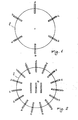
- the duct for supplying electric power according to the present invention is characterized in that all of the conductors forming it are arranged evenly along the points of a single circle, the center of which coincides with the center of gravity of the neutral wire.
- the duct for supplying electric power comprises a plurality of conductors arranged with their centers of gravity along the points of a single circle L, having such a diameter which depends on that of said conductors.
- the same letter indicates all of the conductors of the same polarity.
- this letter is arranged in such a way that its center of gravity coincides with the center of the circle L.
- the conductors have a rectangular corss-section, but it should be apparent that the shape and surface thereof may vary depending on the contingent technical requirements.
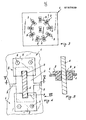
- the conductors a, b or c are supported, inside the duct body (not shown for clarity) by plate members 1, more or less spaced along the duct depending on the provided electrodynamic stresses.
- Each block 3 consists of an insulating base pair 5, affixed by means of bolts 6 to the plate member 1.
- the bases 5 house the conductor 4 inside slots 8 having the same shape as said conductor with a slight clearance in order to fit expansions.
- the altter may be provided with three openings 2, therethrough three conductors of the type a, b, c are passed, said openings being coupled by cuts 9.
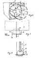
- the conductors may be tangentially arranged with respect to the hypotetical circle thereon they are arranged, whereas the bushings 10 are shaped as small cylinders having a respective groove 8 for receiving the conductors 4 and are provided, oppositedly to the groove 8, with s flat surface 11.
- a sheet metal housing 12 is so shaped as to the house the bushing 10 and is restrained, for example by welding, to the plate member 1.
- the housing 12 laterally projects with respect to the bushing 10 in such a way that a pin pairs 13 is able of preventing the bushings 10 from being laterally shifted, thereby affording the possibility of easily replacing them.
- the procedures or methods for affixing the plate members 1 to the inner part of the duct body may be many, for example welding, bolting to the frame and the like.
Landscapes
- Coils Of Transformers For General Uses (AREA)
- Housings And Mounting Of Transformers (AREA)
Applications Claiming Priority (2)
| Application Number | Priority Date | Filing Date | Title |
|---|---|---|---|
| IT2411084 | 1984-12-18 | ||
| IT24110/84A IT1177444B (it) | 1984-12-18 | 1984-12-18 | Condotto per il trasporto di energia elettrica con ridotti effetti elettrodinamici, di corto circuito e dell'induttanza |
Publications (2)
| Publication Number | Publication Date |
|---|---|
| EP0187939A2 true EP0187939A2 (de) | 1986-07-23 |
| EP0187939A3 EP0187939A3 (de) | 1987-09-30 |
Family
ID=11212026
Family Applications (1)
| Application Number | Title | Priority Date | Filing Date |
|---|---|---|---|
| EP85115346A Withdrawn EP0187939A3 (de) | 1984-12-18 | 1985-12-03 | Leitung zum Versorgen von elektrischer Energie mit reduzierten elektrodynamischen Kurzschluss- und Induktionswirkungen |
Country Status (2)
| Country | Link |
|---|---|
| EP (1) | EP0187939A3 (de) |
| IT (1) | IT1177444B (de) |
Family Cites Families (3)
| Publication number | Priority date | Publication date | Assignee | Title |
|---|---|---|---|---|
| FR1188281A (fr) * | 1957-12-12 | 1959-09-21 | Comp Generale Electricite | Canalisation électrique préfabriquée |
| US2973405A (en) * | 1958-02-21 | 1961-02-28 | Helmuth W Zuch | Electrical distribution bus ducts |
| US3803343A (en) * | 1972-09-12 | 1974-04-09 | E Carlson | Enclosed cablebus setup |
-
1984
- 1984-12-18 IT IT24110/84A patent/IT1177444B/it active
-
1985
- 1985-12-03 EP EP85115346A patent/EP0187939A3/de not_active Withdrawn
Also Published As
| Publication number | Publication date |
|---|---|
| EP0187939A3 (de) | 1987-09-30 |
| IT8424110A0 (it) | 1984-12-18 |
| IT1177444B (it) | 1987-08-26 |
Similar Documents
| Publication | Publication Date | Title |
|---|---|---|
| CA1309473C (en) | Thermally efficient power busway housing | |
| CA1099792A (en) | Busbar system of electric high voltage switchgear | |
| US4886468A (en) | Insulated electrical power distribution busway tabs | |
| US4121276A (en) | Electrical switchboard apparatus with center fed vertical riser bus | |
| US4929801A (en) | Thermally efficient ventilated electric busway system | |
| US4785378A (en) | Loop-feed wiring arrangement for electric circuit breakers and switches | |
| CA1051495A (en) | Biaxial compression phase lead connector | |
| US4307304A (en) | Electrical switchboard apparatus with center fed vertical riser bus | |
| US4136374A (en) | Electrical switchboard apparatus including double-flanged vertical riser conductors | |
| ES8700511A1 (es) | Perfeccionamientos en un rotor de una maquina electrica | |
| US4093970A (en) | Main lug assembly for circuit breaker load centers | |
| US6142807A (en) | High current and low current electrical busway systems having compatible bus plug | |
| EP0187939A2 (de) | Leitung zum Versorgen von elektrischer Energie mit reduzierten elektrodynamischen Kurzschluss- und Induktionswirkungen | |
| GB1560168A (en) | Electrical terminal block | |
| US2008109A (en) | Heavy current conductor system, more particularly for rushes of heavy currents | |
| EP0190551B1 (de) | Gasisolierte Schaltanlage | |
| EP1451911B1 (de) | Trägerisolator | |
| CN210007065U (zh) | 接线装置及输电设备 | |
| JP3073393U (ja) | 配電盤の垂直母線クランピング装置 | |
| CN220234137U (zh) | 一种空气绝缘母线槽 | |
| US6400558B1 (en) | Line deadend structure and method | |
| CA2155218A1 (en) | Multi-phase electric machine with offset multi-polar electric pole units | |
| SU1239795A1 (ru) | Электрическа машина посто нного тока | |
| US20250286359A1 (en) | Additional cover structure for phase insulated medium voltage busbar systems | |
| US3243502A (en) | Interphase support arrangement for isolated phase bus system |
Legal Events
| Date | Code | Title | Description |
|---|---|---|---|
| PUAI | Public reference made under article 153(3) epc to a published international application that has entered the european phase |
Free format text: ORIGINAL CODE: 0009012 |
|
| AK | Designated contracting states |
Kind code of ref document: A2 Designated state(s): AT BE CH DE FR GB IT LI NL SE |
|
| PUAL | Search report despatched |
Free format text: ORIGINAL CODE: 0009013 |
|
| AK | Designated contracting states |
Kind code of ref document: A3 Designated state(s): AT BE CH DE FR GB IT LI NL SE |
|
| STAA | Information on the status of an ep patent application or granted ep patent |
Free format text: STATUS: THE APPLICATION IS DEEMED TO BE WITHDRAWN |
|
| 18D | Application deemed to be withdrawn |
Effective date: 19880331 |
|
| RIN1 | Information on inventor provided before grant (corrected) |
Inventor name: CLIN, MICHEL |