EP0187946B1 - Régulateur de tension électronique avec action à deux directions pour alternateurs - Google Patents
Régulateur de tension électronique avec action à deux directions pour alternateurs Download PDFInfo
- Publication number
- EP0187946B1 EP0187946B1 EP85115588A EP85115588A EP0187946B1 EP 0187946 B1 EP0187946 B1 EP 0187946B1 EP 85115588 A EP85115588 A EP 85115588A EP 85115588 A EP85115588 A EP 85115588A EP 0187946 B1 EP0187946 B1 EP 0187946B1
- Authority
- EP
- European Patent Office
- Prior art keywords
- voltage
- regulator
- electronic
- alternator
- triac
- Prior art date
- Legal status (The legal status is an assumption and is not a legal conclusion. Google has not performed a legal analysis and makes no representation as to the accuracy of the status listed.)
- Expired
Links
- 230000005284 excitation Effects 0.000 claims abstract description 37
- 238000004804 winding Methods 0.000 claims abstract description 19
- 230000000694 effects Effects 0.000 claims description 6
- 230000007423 decrease Effects 0.000 claims description 5
- 238000010276 construction Methods 0.000 abstract description 4
- 150000001875 compounds Chemical class 0.000 description 7
- 238000010586 diagram Methods 0.000 description 7
- 230000004048 modification Effects 0.000 description 4
- 238000012986 modification Methods 0.000 description 4
- 230000001105 regulatory effect Effects 0.000 description 3
- 230000002123 temporal effect Effects 0.000 description 3
- 230000004907 flux Effects 0.000 description 2
- 230000007257 malfunction Effects 0.000 description 2
- 238000000034 method Methods 0.000 description 2
- 230000033228 biological regulation Effects 0.000 description 1
- 238000006073 displacement reaction Methods 0.000 description 1
- 230000006698 induction Effects 0.000 description 1
- 230000003993 interaction Effects 0.000 description 1
Images



Classifications
-
- H—ELECTRICITY
- H02—GENERATION; CONVERSION OR DISTRIBUTION OF ELECTRIC POWER
- H02P—CONTROL OR REGULATION OF ELECTRIC MOTORS, ELECTRIC GENERATORS OR DYNAMO-ELECTRIC CONVERTERS; CONTROLLING TRANSFORMERS, REACTORS OR CHOKE COILS
- H02P9/00—Arrangements for controlling electric generators for the purpose of obtaining a desired output
- H02P9/14—Arrangements for controlling electric generators for the purpose of obtaining a desired output by variation of field
- H02P9/26—Arrangements for controlling electric generators for the purpose of obtaining a desired output by variation of field using discharge tubes or semiconductor devices
- H02P9/30—Arrangements for controlling electric generators for the purpose of obtaining a desired output by variation of field using discharge tubes or semiconductor devices using semiconductor devices
- H02P9/305—Arrangements for controlling electric generators for the purpose of obtaining a desired output by variation of field using discharge tubes or semiconductor devices using semiconductor devices controlling voltage
-
- H—ELECTRICITY
- H02—GENERATION; CONVERSION OR DISTRIBUTION OF ELECTRIC POWER
- H02P—CONTROL OR REGULATION OF ELECTRIC MOTORS, ELECTRIC GENERATORS OR DYNAMO-ELECTRIC CONVERTERS; CONTROLLING TRANSFORMERS, REACTORS OR CHOKE COILS
- H02P9/00—Arrangements for controlling electric generators for the purpose of obtaining a desired output
- H02P9/14—Arrangements for controlling electric generators for the purpose of obtaining a desired output by variation of field
- H02P9/38—Self-excitation by current derived from rectification of both output voltage and output current of generator
Definitions
- the invention concerns an electronic regulation system for alternator excitation, which is liable to be added by means of connectors, or of other connecting means, to an alternator already being provided with its own excitation system.
- the excitation of the compound type is obtained by calculating the vectorial sum of two currents, the one being proportional to the voltage of the generator terminals, the other being proportional tothe phase current, and by rectifying the resulting current.
- the excitation by means of electronic voltage regulator is obtained by taking the voltage from the terminals at the exit of the alternator and comparing it with a reference voltage and by inserting the same into the electronic regulator which supplies the power necessary forthe excitation.
- the mixed excitation on the other hand, foresees a compound which supplies to the machine an insufficient or an excessive excitation, and the electronic regulator, which, as a consequence acts by respectively adding or subtracting.
- the compound excitation presents some advantages, such as, for example, the simplicity and the low-cost of the construction and the relative easiness to excite the machine, even with the low voltages generated by the residual induction, it is also true that said excitation does not insure satisfactory performances, particularly because of some functional conditions: in fact, the voltage stability is rather approximate when the number of revolutions changes and even when the cos (p of the load changes; besides, it is not always easy to obtain parallel performances between alternators being thus excited.
- the regulator In the case of an electronic regulator which compensates by adding to the compound, the regulator itself must also be dimensioned so that it can stand the overloads of the machine, so that its construction becomes rather costly; besides, should a malfunction of the regulator occur, the same type of drawbacks due to the insufficient dimensioning of the compound excitation would present themselves.
- the purpose of the present invention is that of overcoming many of the above-mentioned drawbacks being attributed to the known electronic regulators, by creating an electronic regulator being able to supply excitation voltage both in addition to and in subtraction from the alternator voltage and that being done automatically and so as to insure a constant voltage to the terminals of the alternator, no matter what the load conditions are.
- Another purpose of the invention is that of obtaining that the regulator itself be of limited power and be easy to apply to the alternators, whith out considerable constructive variations to the alternators themselves.
- an electronic voltage regulator for alternators equipped with a self-excitation system wherein said regulator is able to add to, as well to subtract power from the self-excitation system, said regulator supplying an auxiliary excitation current whose direction and intensity depend on the comparison between a reference voltage (124) and the output voltage of the alternator, or a part of it (123), said addition or subtraction being done by electric or magnetic means.
- the regulator can supply power in both directions, it can act in the circuits belonging to the alternator both by adding to or subtracting from the power being present in said circuits.
- the algebraic sum of the excitation power belonging to the alternator and the power produced by the electronic regulator can be obtained causing the circuits of the regulator and those of the alternator to interact both magnetically and electrically.
- the alternator is provided both with its own excitation winding and with an auxiliary winding, so that the resulting fluxes add themselves up or subtract themselves, thereby increasing or lowering the alternator excitation flux.
- an alternator 110 equipped with its own excitation system 111, acting through the excitation windings 112, is equipped with some windings for auxiliary excitation 113, the power of which is provided by the electronic regulator 114 being the object of the invention.
- the functional diagram of the device is represented in Fig. 2 and it includes a device 121 being able to conduct power in two directions and a corresponding control circuit 122 being able to control the conduction of circuit 121, so that the power produced by it and circulating within the auxiliary winding 113, has an intensity and a direction being the result of the comparison between a reference voltage 124 and the voltage produced by the alternator (or a part of it) 123.
- a particularly advantageous realization of the circuit having a two-directional conduction 121 is obtained by using triac 210 as a component, as shown in Fig. 3.
- This circuit is fed at the terminals A and B by an auxiliary alternate voltage 211, which may be the exit voltage of the alternator or a part of it, or a voltage generated by a separate winding of the alternator or even supplied by an independent source.
- auxiliary alternate voltage 211 which may be the exit voltage of the alternator or a part of it, or a voltage generated by a separate winding of the alternator or even supplied by an independent source.
- a series of ingoing impulses 212 arrive, which are produced by a control circuit and trigger the conduction of TRIAC 210.
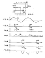
- Said impulses produce in the reactance 113 of circuit 121 of Fig. 3, currents having opposite directions according to the temporal instant at which they occur, in relation to the movement of the auxiliary voltage 211.
- the triggering impulses 212 also being generated by the control circuit 122, occur in the temporal instants 261 and 262 (Fig. 8, during the negative semi-wave of voltage 211, then the voltage at the terminals of reactance 113 acquires a negative value having the same movement as represented in Fig. 9, and the same happens to the current lm, which also becomes negative (Fig. 10).
- the main function required of the electronic regulator is achieved, i.e. that of producing an uxiliary excitation current, which, once the direction of the auxiliary winding 113 has been fixed, adds itself to or subtracts itself from the excitation of the alternator itself, according to the direction which said current takes, depending on the triggering instant of the TRIAC.
- a voltage 123 being present at the exit of the alternator, for instance between two terminals at the exit, is introduced or, in any case, a part being proportional to said voltage.
- the alternate voltage 123 is converted, through the rectifying circuit with the capacitive filter indicated with 311, into a direct voltage 321 being proportional to it and it is introduced into the inverting entrance of a differential amplifier 312, where, into the noninverting entrance 322 a reference direct voltage 124 is fed through terminal E.
- auxiliary alternate voltage 211 in reference to which the triggering instants of TRIAC 210 have previously been referred to (see Figs. 4 to 10), and which, for convenience of representation, has been repeated in Fig. 12, is applied to the terminals FG of circuit 122, and, through a dephasing circuit RC 310, an alternate voltage 320 is obtained, which is dephased by approximately 90° in comparison with voltage 211, as shown in Fig. 13.
- the same voltage 320 is also inserted into the inverting amplifier 313 having a unitary gain, so that it comes out dephased by 180° as shown in Fig. 14, where said wave-shape is represented with reference 330.
- the direct signal 323 also goes into a similar inverting amplifier 314 having a unitary gain and it comes out with a changed sign, indicated with 331 in Fig. 15.
- the two signals 330 and 331 then go into adder 315 and they generate the total signal 324 shown in Fig. 15.
- Fig. 15 it can be observed that the wave shapes 324 and 325 are symmetrical in relation to the axis of the abscissas.
- the signals 324 and 325 tend to mutually increase or decrease the distance between each other, to the point of even interchanging their respective quadrants, while maintaining the symmetry in relation to the axis of the abscissas.
- Signal 326 given by the positive parts of the signals 324 and 325, reaches the impulse generating circuit 319, through the diodes 317 and 318, as shown in Fig. 16.
- the triggering impulse generator 319 produces, by means of the comparison with a pre-determined reference 341, the exciting impulses 212 in the instants 231 and 232.
- the exciting impulse will occur during the positive semi-wave of voltage 211 at the same instant at which wave 326 oversteps the threshold of the pre-determined reference 341.
- a corresponding variation of voltage 123 being applied to the control circuit 122 also occurs, and in turn it produces a variation having the opposite sign of the direct voltage 323, which, as a consequence, has a displacement of the sinusoidal waves 325 and 324, so that the triggering impulses 212 position themselves in such a way, as to vary the value and the sign of the current of the auxiliary excitation; from this the ensuing variation in the return of the alternator voltage is obtained.
- Fig. 17 An alternative solution, yet having an equal effect to that of the regulating circuit illustrated in Fig. 3, is shown in Fig. 17, where TRIAC 210 is replaced by a pair of controlled diodes being connected in inverted parallel.
- the functioning of the system is virtually identical, but, in order to insure an appropriate triggering of the controlled diodes, some modifications of the control circuit 122 are necessary. Said modifications imply techniques known to the expert.
- FIG. 18 Yet another variation of the electronic regulator is shown in Fig. 18.
- the circuit reproduced here is fed by a unidirectional and pulsing voltage (400) positioned between the terminals LM in replacement of the preceding auxiliary voltage 211; Said voltage 400 can be obtained, for instance, by rectifying voltage 211 itself.
- a unidirectional and pulsing voltage 400
- Said voltage 400 can be obtained, for instance, by rectifying voltage 211 itself.
- two controlled diodes 410 and 411 are used in the circuit. They are connected to two separate auxiliary windings 412 and 413, being wound in the opposite directions. In this case the addition or subtraction effect in relation to the excitation belonging to the alternator is obtained by causing either one of the two controlled diodes to conduct, thereby sending current into either one of the auxiliary windings.
- the impulses 212 turning on the controlled diodes will be supplied circuitously by a control circuit being different from the control circuit 122, but having virtually identical functions.
- FIG. 19 Yet another variation of the electronic regulator shown in Fig. 3, is shown in Fig. 19. Only one auxiliary winding 425 is present in this circuit, but, in order to obtain that the current moves in both directions of winding 425, four controlled diodes, marked with 421,422,423 and 424, are necessary. Said diodes are positioned so that they will conduct in crossed pairs, such as 421 and 423 or 422 and 424.
- the applied voltage 400 must be of the pulsing and unidirectional type in order to guarantee the turning off of the devices when the impulse stops.
Landscapes
- Engineering & Computer Science (AREA)
- Power Engineering (AREA)
- Control Of Eletrric Generators (AREA)
- Ignition Installations For Internal Combustion Engines (AREA)
- Details Of Television Scanning (AREA)
Claims (6)
Priority Applications (1)
| Application Number | Priority Date | Filing Date | Title |
|---|---|---|---|
| AT85115588T ATE46234T1 (de) | 1984-12-14 | 1985-12-07 | Elektronischer spannungsregler mit zweigerichteter wirkung fuer wechselspannungserzeuger. |
Applications Claiming Priority (2)
| Application Number | Priority Date | Filing Date | Title |
|---|---|---|---|
| IT85669/84A IT1181799B (it) | 1984-12-14 | 1984-12-14 | Regolatore elettronico della tensione ad azione bidirezionale per alternatori |
| IT8566984 | 1984-12-14 |
Publications (2)
| Publication Number | Publication Date |
|---|---|
| EP0187946A1 EP0187946A1 (fr) | 1986-07-23 |
| EP0187946B1 true EP0187946B1 (fr) | 1989-09-06 |
Family
ID=11329698
Family Applications (1)
| Application Number | Title | Priority Date | Filing Date |
|---|---|---|---|
| EP85115588A Expired EP0187946B1 (fr) | 1984-12-14 | 1985-12-07 | Régulateur de tension électronique avec action à deux directions pour alternateurs |
Country Status (7)
| Country | Link |
|---|---|
| US (1) | US4733157A (fr) |
| EP (1) | EP0187946B1 (fr) |
| AT (1) | ATE46234T1 (fr) |
| AU (1) | AU575703B2 (fr) |
| CA (1) | CA1256160A (fr) |
| DE (1) | DE3572901D1 (fr) |
| IT (1) | IT1181799B (fr) |
Families Citing this family (6)
| Publication number | Priority date | Publication date | Assignee | Title |
|---|---|---|---|---|
| DE4016573C1 (fr) * | 1990-05-23 | 1991-08-29 | Mercedes-Benz Aktiengesellschaft, 7000 Stuttgart, De | |
| US5486751A (en) * | 1992-02-27 | 1996-01-23 | Onan Corporation | Electronic trimming voltage regulator |
| AU687847B2 (en) * | 1993-06-14 | 1998-03-05 | Ecoair Corp. | Hybrid alternator with voltage regulator |
| US5408067A (en) * | 1993-12-06 | 1995-04-18 | The Lincoln Electric Company | Method and apparatus for providing welding current from a brushless alternator |
| EP1320186A1 (fr) * | 2001-12-07 | 2003-06-18 | Linz Electric S.r.l. | Dispositif de régulation de la tension de sortie pour alternateurs |
| US10250173B1 (en) * | 2017-09-19 | 2019-04-02 | Kutai Electronics Industry Co., Ltd. | Power generator system and generator exciter device thereof |
Family Cites Families (10)
| Publication number | Priority date | Publication date | Assignee | Title |
|---|---|---|---|---|
| US3521148A (en) * | 1963-09-20 | 1970-07-21 | Gen Motors Corp | Semiconductor voltage regulator for a generator with main and bucking field windings |
| FR1392698A (fr) * | 1964-01-28 | 1965-03-19 | Alsthom Cgee | Système d'excitation série pour machine électrique à courant continu |
| CH477125A (de) * | 1967-08-05 | 1969-08-15 | Siemens Ag | Einrichtung zur kontinuierlichen Veränderung der Felderregung eines Gleichstromgenerators |
| AT280437B (de) * | 1968-03-01 | 1970-04-10 | Siemens Gmbh | Einrichtung zur Selbsterregung von Synchronmaschinen |
| US3512076A (en) * | 1968-09-11 | 1970-05-12 | Gen Motors Corp | Transistor voltage regulating system for generators having main and reverse field windings |
| US3713016A (en) * | 1972-02-03 | 1973-01-23 | Gen Motors Corp | Generator field coil energizing reversing circuit |
| JPS4947810A (fr) * | 1972-08-23 | 1974-05-09 | ||
| GB1478297A (en) * | 1974-08-08 | 1977-06-29 | Contrology Tech Ltd | Control circuit for electric alternators |
| JPS5524358B2 (fr) * | 1975-02-10 | 1980-06-28 | ||
| DE3035819A1 (de) * | 1980-09-23 | 1982-05-06 | Robert Bosch Gmbh, 7000 Stuttgart | Selbsterregter elektrischer generator |
-
1984
- 1984-12-14 IT IT85669/84A patent/IT1181799B/it active
-
1985
- 1985-12-07 EP EP85115588A patent/EP0187946B1/fr not_active Expired
- 1985-12-07 AT AT85115588T patent/ATE46234T1/de not_active IP Right Cessation
- 1985-12-07 DE DE8585115588T patent/DE3572901D1/de not_active Expired
- 1985-12-10 AU AU51076/85A patent/AU575703B2/en not_active Ceased
- 1985-12-11 CA CA000497409A patent/CA1256160A/fr not_active Expired
- 1985-12-12 US US06/808,063 patent/US4733157A/en not_active Expired - Lifetime
Also Published As
| Publication number | Publication date |
|---|---|
| CA1256160A (fr) | 1989-06-20 |
| ATE46234T1 (de) | 1989-09-15 |
| IT1181799B (it) | 1987-09-30 |
| US4733157A (en) | 1988-03-22 |
| DE3572901D1 (en) | 1989-10-12 |
| IT8485669A0 (it) | 1984-12-14 |
| AU5107685A (en) | 1986-06-19 |
| AU575703B2 (en) | 1988-08-04 |
| EP0187946A1 (fr) | 1986-07-23 |
Similar Documents
| Publication | Publication Date | Title |
|---|---|---|
| EP0187946B1 (fr) | Régulateur de tension électronique avec action à deux directions pour alternateurs | |
| US3619761A (en) | Excitation control device of self-exciting, compound synchronous machine | |
| US3022453A (en) | Direct current speed drive system | |
| US3211987A (en) | Excitation system for a dynamoelectric machine | |
| GB1282455A (en) | Rectifier controlled apparatus for an a.c. generator excitation system | |
| US2728044A (en) | Regulator systems | |
| US2186847A (en) | Regulating system | |
| US3496448A (en) | Static converter with means responsive to a decrease in output voltage | |
| US2474647A (en) | Speed control of dynamoelectric machines | |
| US2325407A (en) | Dynamoelectric machine | |
| US1893354A (en) | Arc welding system | |
| US2740084A (en) | Voltage regulating system | |
| US3278831A (en) | Regulator systems for self-excited direct current generators | |
| US3287619A (en) | Permanent magnet generator output control | |
| US2483151A (en) | Dynamoelectric machine | |
| US366349A (en) | Regulator for self-exciting alternate-current electric generators | |
| US2749500A (en) | Voltage deviation detector | |
| US2119406A (en) | Electric circuit control means | |
| US2012884A (en) | Regulating vapor electric discharge rectifier | |
| US2246150A (en) | Electric valve circuit | |
| US1633808A (en) | Regulating system for dynamo-electric machines | |
| US2585145A (en) | Synchronous dynamoelectric machine | |
| US1909104A (en) | Regulator compensator | |
| US1663891A (en) | Regulator system employing electron-discharge devices | |
| US1694253A (en) | Regulating system |
Legal Events
| Date | Code | Title | Description |
|---|---|---|---|
| PUAI | Public reference made under article 153(3) epc to a published international application that has entered the european phase |
Free format text: ORIGINAL CODE: 0009012 |
|
| AK | Designated contracting states |
Kind code of ref document: A1 Designated state(s): AT BE CH DE FR GB LI LU NL |
|
| 17P | Request for examination filed |
Effective date: 19861002 |
|
| 17Q | First examination report despatched |
Effective date: 19880218 |
|
| GRAA | (expected) grant |
Free format text: ORIGINAL CODE: 0009210 |
|
| AK | Designated contracting states |
Kind code of ref document: B1 Designated state(s): AT BE CH DE FR GB LI LU NL |
|
| REF | Corresponds to: |
Ref document number: 46234 Country of ref document: AT Date of ref document: 19890915 Kind code of ref document: T |
|
| REF | Corresponds to: |
Ref document number: 3572901 Country of ref document: DE Date of ref document: 19891012 |
|
| ET | Fr: translation filed | ||
| PG25 | Lapsed in a contracting state [announced via postgrant information from national office to epo] |
Ref country code: LU Free format text: LAPSE BECAUSE OF NON-PAYMENT OF DUE FEES Effective date: 19891231 |
|
| PLBE | No opposition filed within time limit |
Free format text: ORIGINAL CODE: 0009261 |
|
| STAA | Information on the status of an ep patent application or granted ep patent |
Free format text: STATUS: NO OPPOSITION FILED WITHIN TIME LIMIT |
|
| 26N | No opposition filed | ||
| PGFP | Annual fee paid to national office [announced via postgrant information from national office to epo] |
Ref country code: AT Payment date: 19941219 Year of fee payment: 10 |
|
| PGFP | Annual fee paid to national office [announced via postgrant information from national office to epo] |
Ref country code: CH Payment date: 19941222 Year of fee payment: 10 |
|
| PGFP | Annual fee paid to national office [announced via postgrant information from national office to epo] |
Ref country code: NL Payment date: 19941231 Year of fee payment: 10 |
|
| PG25 | Lapsed in a contracting state [announced via postgrant information from national office to epo] |
Ref country code: AT Effective date: 19951207 |
|
| PG25 | Lapsed in a contracting state [announced via postgrant information from national office to epo] |
Ref country code: LI Effective date: 19951231 Ref country code: CH Effective date: 19951231 |
|
| PG25 | Lapsed in a contracting state [announced via postgrant information from national office to epo] |
Ref country code: NL Effective date: 19960701 |
|
| REG | Reference to a national code |
Ref country code: CH Ref legal event code: PL |
|
| NLV4 | Nl: lapsed or anulled due to non-payment of the annual fee |
Effective date: 19960701 |
|
| PGFP | Annual fee paid to national office [announced via postgrant information from national office to epo] |
Ref country code: BE Payment date: 19961212 Year of fee payment: 12 |
|
| PG25 | Lapsed in a contracting state [announced via postgrant information from national office to epo] |
Ref country code: BE Free format text: LAPSE BECAUSE OF NON-PAYMENT OF DUE FEES Effective date: 19971231 |
|
| BERE | Be: lapsed |
Owner name: M.E.C.C. ALTE S.P.A. Effective date: 19971231 |
|
| PGFP | Annual fee paid to national office [announced via postgrant information from national office to epo] |
Ref country code: FR Payment date: 20001129 Year of fee payment: 16 |
|
| PGFP | Annual fee paid to national office [announced via postgrant information from national office to epo] |
Ref country code: GB Payment date: 20001207 Year of fee payment: 16 |
|
| PGFP | Annual fee paid to national office [announced via postgrant information from national office to epo] |
Ref country code: DE Payment date: 20010222 Year of fee payment: 16 |
|
| PG25 | Lapsed in a contracting state [announced via postgrant information from national office to epo] |
Ref country code: GB Free format text: LAPSE BECAUSE OF NON-PAYMENT OF DUE FEES Effective date: 20011207 |
|
| REG | Reference to a national code |
Ref country code: GB Ref legal event code: IF02 |
|
| PG25 | Lapsed in a contracting state [announced via postgrant information from national office to epo] |
Ref country code: DE Free format text: LAPSE BECAUSE OF NON-PAYMENT OF DUE FEES Effective date: 20020702 |
|
| GBPC | Gb: european patent ceased through non-payment of renewal fee |
Effective date: 20011207 |
|
| PG25 | Lapsed in a contracting state [announced via postgrant information from national office to epo] |
Ref country code: FR Free format text: LAPSE BECAUSE OF NON-PAYMENT OF DUE FEES Effective date: 20020830 |
|
| REG | Reference to a national code |
Ref country code: FR Ref legal event code: ST |