EP0187964B1 - Unité de déviation électromagnétique corrigeant la faute de distorsion - Google Patents
Unité de déviation électromagnétique corrigeant la faute de distorsion Download PDFInfo
- Publication number
- EP0187964B1 EP0187964B1 EP85115857A EP85115857A EP0187964B1 EP 0187964 B1 EP0187964 B1 EP 0187964B1 EP 85115857 A EP85115857 A EP 85115857A EP 85115857 A EP85115857 A EP 85115857A EP 0187964 B1 EP0187964 B1 EP 0187964B1
- Authority
- EP
- European Patent Office
- Prior art keywords
- permanent magnets
- electromagnetic deflection
- auxiliary permanent
- distortion
- deflection
- Prior art date
- Legal status (The legal status is an assumption and is not a legal conclusion. Google has not performed a legal analysis and makes no representation as to the accuracy of the status listed.)
- Expired
Links
Images



Classifications
-
- H—ELECTRICITY
- H01—ELECTRIC ELEMENTS
- H01J—ELECTRIC DISCHARGE TUBES OR DISCHARGE LAMPS
- H01J29/00—Details of cathode-ray tubes or of electron-beam tubes of the types covered by group H01J31/00
- H01J29/46—Arrangements of electrodes and associated parts for generating or controlling the ray or beam, e.g. electron-optical arrangement
- H01J29/70—Arrangements for deflecting ray or beam
- H01J29/701—Systems for correcting deviation or convergence of a plurality of beams by means of magnetic fields at least
Definitions
- This invention relates to a deflection-distortion corrector for a cathode-ray tube (CRT) display unit, and more specifically to such a corrector using permanent magnets.
- CTR cathode-ray tube
- a system known as electromagnetic deflection For the deflection of electron beam in CRT display units, a system known as electromagnetic deflection is predominantly used.
- the system as typically shown in Fig. 2, employs horizontal and vertical deflection coils 3 arranged around the neck of the CRT 2 having a phosphor screen 1 and supplied with a current to deflect the path of electron beam 4 scanning the screen. Close to the deflection coils, there is usually provided a deflection yoke of a high-permeability ferrite core.
- a countermeasure usually taken is a system of electronic circuits for adjusting the deflecting current to the optimum value for each of the horizontal and vertical coordinate points, a system of permanent magnets arranged close to the deflection coils to correct the residual distortion in each magnetic field they generate in the space, or both.
- the permanent magnet system is less expensive because they use fixed magnets, but permanent magnets of proper length and strength in proper arrangement are so complex to design that high-accuracy deflection distortion correction by the system is seldom realized.
- the permanent magnet system in use will now be explained by reference to Figs. 1 and 4 illustrating the present invention.
- a horizontal deflection coil 13
- a vertical deflection coil 12 and a conical deflection yoke 11.
- four bar-shaped permanent magnets 14 are also disposed (Fig. 4).
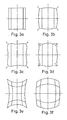
- the visual presentation on a CRT display unit is, ideally, required to be of good linearity as represented by the raster in Fig. 3a.
- correction by the permanent magnet system leaves residual distortions as in Fig. 3b, Fig. 3c or Fig. 3d, necessitating adjustments in the directions of the arrows.
- An attempt to combine the system with another corrector means of electronic circuits presents other problems of inevitable residual distortion where weight is placed on cost reduction, or very high cost of complete correction. Precise correction by the electronic circuits alone is again extremely costly.
- a deflection-distortion corrector system which comprises a plurality of rubber magnets which are symmetrically arranged around an insulating sleeve disposed on the neck of a cathode-ray tube.
- Each of the magnets is carried on a peg the axis of which is inclined with respect to the axis of the cathode-ray tube.
- the magnets are adapted to be moved forwardly and backwardly in the direction of the axis of the associated peg. Furthermore the magnets can be rotated about this axis.
- the present invention aims at providing means for enabling a distortion corrector for a CRT display unit of the electromagnetic deflection type to perform the correction of distortions simply, economically, and with high accuracy.
- the invention thus provides an electromagnetic deflection-distortion corrector comprising a plurality of fixed main permanent magnets symmetrically arranged around the tubular wall of a cathode-ray tube of electromagnetic deflection type, a plurality of movable auxiliary permanent magnets symmetrically arranged around said tubular wall, and adjuster means for moving each auxiliary permanent magnet forwardly and backwardly in the direction of the axis of the cathode-ray tube, said auxiliary permanent magnets having magnetization in a direction normal to the direction of the movement of said auxiliary permanent magnets.
- the rough correction obtained by the distortion-correcting main permanent magnets is combined with the fine adjustment by the auxiliary permanent magnets, wherein the magnitude and direction of the magnetic field produced by each auxiliary or fine adjusting permanent magnet and applicable to each coordinate point that requires fine adjustment may be freely chosen as desired.
- each point that needs correction can be corrected in a desired direction over a desired distance, and high-accuracy correction is accomplished in a simple and economical way.
- the fine-adjusting permanent magnets according to the invention are held by support means in such a manner that their back-and-forth movement parallel to the axis of the CRT, and their angle of rotation are adjustable by screw means or the like. In this way the direction and magnitude of the magnetic field each magnet produces can be arbitrarily set with respect to the particular coordinate point where adjustment is to be made.
- These permanent magnets have only to be provided in a number (eight, in the embodiment being described) corresponding to the number of coordinate points requiring precise correction.
- the screw or other similar means must simply force the individual magnets toward or away from the path of electron beam corresponding to given coordinate points.
- a horizontal deflection coil 12 Around the conical tube wall at the neck of a CRT 10 are fitted, in the usual manner, a horizontal deflection coil 12, a vertical deflection coil 13, and a deflection yoke 11 of sintered ferrite material.
- These components are not limited in design and structure to those shown but other known components of different designs or structures may be employed instead.
- distortion-correcting main permanent magnets 14 are carried by an appropriate nonmagnetic support frame 15 around the deflection yoke and coils. These main permanent magnets act to correct the pincushion distortion of Fig. 3e or barrel distortion of in Fig. 3f to the form shown in Fig. 3b, Fig. 3c or Fig. 3d. The deflected image must be further corrected in the direction of arrows.
- fine-adjusting permanent magnets 16 are arranged, in addition to the main permanent magnets 14, around the CRT, so that the smaller magnetic field of each fine-adjusting magnet acts on the path 17 of electron beam to effect desired correction.
- the inwardly extending annular flange of the support frame 15 made of plastic or other nonmagnetic material has a plurality of retainers or supports in the form of threaded holes 18 at points conforming to the points where the raster correction is to be done. With these holes are engaged a corresponding number of the permanent magnets 16 each of which, as enlarged in Fig. 6, is externally threaded and diametrally magnetized.
- the magnets also have a slot or recess formed in one end to receive the tip of a screwdriver.
- the threaded holes 18 of the support frame are extended away from the tube wall to a length enough to provide an adequate distance for movement of the individual permanent magnets 16. Desirably, the locations of these holes are fixed so that, when each magnet has been retracted to the full, its magnetic field is substantially completely absorbed by the deflection yoke 11.
- the strength of the permanent magnets 16 is so chosen as to enable each magnet to make the necessary amount of correction when it has moved to the point nearest to the CRT wall.
- the direction of magnetization of each fine-adjusting permanent magnet 16 turns as the magnet moves in thread engagement with the hole. In this way the magnitude and intensity of the correcting magnetic field applied to a preselected position inside the CRT wall can be freely changed within the range of magnetization of the permanent magnet 16.
- FIG. 7 there is shown a cylindrical magnet 16 held by a partly threaded support 19, as compared with the fine-adjusting permanent magnet 16 of Fig. 1 which is threaded on itself.
- the magnet 16 in this embodiment with its direction of magnetization at right angles to the axis of the threaded shank of the support, functions and achieves effects in the same manner as with the preceding embodiment.
- the present invention is characterized in that, in a distortion correction system using fine-adjusting permanent magnets arranged close to the deflection coils external to the CRT, the direction of magnetization of each fine-adjusting permanent magnet is turned through 360 deg. to any desired direction as the magnet moves ahead toward, or backward away from, the confronting wall of the CRT.
- the correction magnetic field applied to the path of electron beam is allowed to have a desired magnitude and direction and thereby correct any deflection distortion to the normal distortionless state.
- Proper choice of the surface magnetic flux density and total number of produced magnetic fluxes of the fine-adjusting permanent magnets 16, the number of magnets, pitch and lead of screw thread thereon, etc. makes it possible to design with ease a corrector capable of fine adjustments with desired accuracy.
- the fine-adjusting magnet was revolved and translated using thread.
- the threaded shank is replaced by a radially magnetized cylindrical bar permanent magnet 16 which is supported by a more than semi-cylindrical inner surface of a non-magnetic retainer 20 secured to the support frame 15.
- the retainer 20 includes a pair of resilient walls which bear against the surface of the cylindrical bar magnet 16.
- a rectangular bar 21 of a handle 22 extends through the complemental axial hole of the magnet 16. Manual operation of the handle 22 allows an efficient axial positioning of the magnet 16 as well as angular positioning.
- Fig. 10 illustrates a further embodiment of the invention.
- the main correction permanent magnets 14 are supported by the support frame 15.
- Fine-adjusting permanent magnets 16 and 17 are respectively supported by retainers 20 and 18 secured to the support frame 15.
- the magnets 16 and the supports 20 are similar to that of the embodiment in Fig. 9 but may be those of the other embodiments.
- the magnets 17 are rectangular in cross section as they are not required to be revolved for fine correction of distortion because the distortion corrections on the horizontal and vertical lines passing through the center of the CRT are needed only in the directions along these two lines (See Fig. 3b, Fig.3c and Fig.3d.
- the bar magnets 17 can only be adjusted axially and the resilient retainers 18 prevent them from rotating.
- More concrete structure of the magnets 17 and the retainers 18 may be one of those illustrated in Figs. 11, 12, 13 and 14 (the members 21, 22 are omitted in Figs. 13 and 14).
Landscapes
- Video Image Reproduction Devices For Color Tv Systems (AREA)
Claims (5)
- Un correcteur de distorsion de déflexion électromagnétique, comprenant un ensemble d'aimants permanents principaux fixes (14), disposés symétriquement autour de la paroi tubulaire d'un tube cathodique (10) du type à déflexion électromagnétique, un ensemble d'aimants permanents auxiliaires mobiles (16, 17) disposés symétriquement autour de la paroi tubulaire, et des moyens de réglage (18, 19, 20) pour déplacer chaque aimant permanent auxiliaire vers l'avant et vers l'arrière dans la direction de l'axe du tube cathodique, ces aimants permanents auxiliaires étant aimantés dans une direction perpendiculaire à la direction du mouvement des aimants permanents auxiliaires.
- Un correcteur de distorsion de déflexion électromagnétique selon la revendication 1, dans lequel chacun des moyens de réglage (18, 19, 20) est également conçu pour faire tourner l'aimant permanent auxiliaire respectif (16).
- Un correcteur de distorsion de déflexion électromagnétique selon la revendication 2, dans lequel chacun des aimants permanents auxiliaires (16) comporte une partie filetée extérieurement qui est vissée dans un support fixe (18).
- Un correcteur de distorsion de déflexion électromagnétique selon la revendication 2, dans lequel chacun des aimants permanents auxiliaires (16) a une surface cylindrique lisse et il est supporté par un élément de retenue élastique (20).
- Un correcteur de distorsion de déflexion électromagnétique selon la revendication 1, dans lequel les aimants permanents auxiliaires (17) qui sont disposés sur l'axe vertical et/ou horizontal passant par le centre du tube (10) ont une section transversale rectangulaire et sont supportés par des éléments de retenue élastiques (18).
Applications Claiming Priority (2)
| Application Number | Priority Date | Filing Date | Title |
|---|---|---|---|
| JP261826/84 | 1984-12-13 | ||
| JP59261826A JPS61140031A (ja) | 1984-12-13 | 1984-12-13 | 電磁偏向歪補正装置 |
Publications (2)
| Publication Number | Publication Date |
|---|---|
| EP0187964A1 EP0187964A1 (fr) | 1986-07-23 |
| EP0187964B1 true EP0187964B1 (fr) | 1991-06-12 |
Family
ID=17367269
Family Applications (1)
| Application Number | Title | Priority Date | Filing Date |
|---|---|---|---|
| EP85115857A Expired EP0187964B1 (fr) | 1984-12-13 | 1985-12-12 | Unité de déviation électromagnétique corrigeant la faute de distorsion |
Country Status (4)
| Country | Link |
|---|---|
| US (1) | US4714908A (fr) |
| EP (1) | EP0187964B1 (fr) |
| JP (1) | JPS61140031A (fr) |
| DE (1) | DE3583228D1 (fr) |
Families Citing this family (11)
| Publication number | Priority date | Publication date | Assignee | Title |
|---|---|---|---|---|
| FR2598809B1 (fr) * | 1986-05-13 | 1988-07-22 | Thomson Cgr | Bloc correcteur d'homogeneite de champ magnetique et aimant muni de tels blocs |
| US5028898A (en) * | 1988-08-24 | 1991-07-02 | Hitachi, Ltd. | Color cathode-ray tube having deflection yoke |
| JPH0793200B2 (ja) * | 1991-08-12 | 1995-10-09 | 住友電気工業株式会社 | 多極ウィグラ |
| EP0551027B1 (fr) * | 1992-01-10 | 1997-09-17 | THOMSON TUBES & DISPLAYS S.A. | Appareil à focalisation magnétique |
| EP0562200B1 (fr) * | 1992-03-27 | 1996-08-14 | THOMSON TUBES & DISPLAYS S.A. | Système de focalisation à aimants permanents ayant un correcteur d'astigmatisme intégré |
| JPH09180652A (ja) * | 1995-12-27 | 1997-07-11 | Sony Corp | 偏向ヨーク |
| FR2754636B1 (fr) * | 1996-10-15 | 1998-11-27 | Thomson Tubes & Displays | Systeme de deviation de faisceau d'electrons pour tube a rayons catholiques monochrome |
| JP3379085B2 (ja) | 1998-02-26 | 2003-02-17 | 日本ビクター株式会社 | 偏向ヨーク及びネジコアの製造方法 |
| TW412056U (en) * | 1998-10-26 | 2000-11-11 | Koninkl Philips Electronics Nv | Picture display device comprising a deflection unit, and deflection unit for such a picture display device |
| US6573817B2 (en) | 2001-03-30 | 2003-06-03 | Sti Optronics, Inc. | Variable-strength multipole beamline magnet |
| FR2824184B1 (fr) * | 2001-04-27 | 2003-09-26 | Thomson Licensing Sa | Tube cathodique en couleurs avec blindage magnetique interne |
Family Cites Families (13)
| Publication number | Priority date | Publication date | Assignee | Title |
|---|---|---|---|---|
| US2899579A (en) * | 1959-08-11 | Cathode ray tubes or the like - | ||
| US2883569A (en) * | 1956-01-24 | 1959-04-21 | Herman F Kaiser | Magnetic quadrupole focusing system |
| US3247426A (en) * | 1963-01-23 | 1966-04-19 | Gen Electric | Deflection control device for cathode ray tubes |
| DE1439534A1 (de) * | 1964-09-11 | 1968-12-19 | Standard Elek K Lorenz Ag | Anordnung zur Geometrieentzerrung bei Elektronenstrahlroehren,insbesondere Fernsehbildroehren |
| DE2143282C3 (de) * | 1971-08-30 | 1980-12-04 | Draegerwerk Ag, 2400 Luebeck | Gasspür- bzw. Staubspür- und -meßgerät |
| US3781731A (en) * | 1973-03-23 | 1973-12-25 | L Poel | Purity and blue lateral assembly for delta beam type cathode ray tube |
| US3942146A (en) * | 1974-11-21 | 1976-03-02 | General Instrument Corporation | Purity adjusting device for slotted mask in-line color picture tubes |
| DE2621711C2 (de) * | 1976-05-15 | 1978-11-02 | Licentia Patent-Verwaltungs-Gmbh, 6000 Frankfurt | Ablenkeinheit für einen Fernsehempfänger mit Permanentmagneten zur Beseitigung von Geometriefehlern |
| JPS5324726A (en) * | 1976-08-20 | 1978-03-07 | Hitachi Ltd | Color receiving tube |
| JPS542623A (en) * | 1977-06-08 | 1979-01-10 | Toshiba Corp | Color picture tube of beam-index type |
| US4198614A (en) * | 1978-11-06 | 1980-04-15 | Rca Corporation | Deflection yoke assembly including a beam positioning magnet arrangement |
| JPS5568054A (en) * | 1978-11-16 | 1980-05-22 | Sony Corp | Electron beam alignment device |
| US4456853A (en) * | 1981-07-06 | 1984-06-26 | Tektronix, Inc. | Feedback CRT for use in a closed-loop correction system |
-
1984
- 1984-12-13 JP JP59261826A patent/JPS61140031A/ja active Pending
-
1985
- 1985-12-06 US US06/806,167 patent/US4714908A/en not_active Expired - Fee Related
- 1985-12-12 EP EP85115857A patent/EP0187964B1/fr not_active Expired
- 1985-12-12 DE DE8585115857T patent/DE3583228D1/de not_active Expired - Fee Related
Also Published As
| Publication number | Publication date |
|---|---|
| US4714908A (en) | 1987-12-22 |
| JPS61140031A (ja) | 1986-06-27 |
| EP0187964A1 (fr) | 1986-07-23 |
| DE3583228D1 (de) | 1991-07-18 |
Similar Documents
| Publication | Publication Date | Title |
|---|---|---|
| US2431077A (en) | Cathode-ray tube with revolving magnets and adjustable sleeve | |
| EP0187964B1 (fr) | Unité de déviation électromagnétique corrigeant la faute de distorsion | |
| US4143345A (en) | Deflection yoke with permanent magnet raster correction | |
| JPH0736623B2 (ja) | インラインカラ−受像管装置 | |
| JP2628648B2 (ja) | 陰極線管 | |
| US4396897A (en) | Cathode ray tube having permanent magnets for modulating the deflection field | |
| US2525919A (en) | Centering arrangement for cathode-ray tubes | |
| KR100251601B1 (ko) | 감소된 스폿 성장을 갖는 컬러 디스플레이 튜브 시스템 | |
| KR880001900B1 (ko) | 동적편향장으로 변조될 수 있는 정적 다극장을 발생하는 영구 자석세트를 가진 편향유니트를 가지고 있는 음극선관 | |
| EP0404243B1 (fr) | Tube image couleur muni de moyens de correction de la torsion des faisceaux | |
| US4296359A (en) | Television display error correction | |
| CA1093625A (fr) | Appareil produisant un champ magnetique octopolaire statique pour corriger la distorsion de trame d'un telecouleur | |
| KR940003047B1 (ko) | 비디오 표시 장치 | |
| KR100235518B1 (ko) | 빔 스폿을 조절하는 편향 시스템 | |
| US4401917A (en) | Color display tube including cylindrical dipole correction magnets | |
| KR100240100B1 (ko) | 음극선관장치의 래스터 일그러짐 보정장치 | |
| GB2037068A (en) | Deflection yoke assembly including a beam positioning magnet arrangement | |
| EP0197573B1 (fr) | Tube image | |
| JP2708488B2 (ja) | カラーブラウン管用マグネット装置 | |
| US5719476A (en) | Apparatus for correcting distortion of an electron beam generated spot on a cathode ray tube screen | |
| US4395692A (en) | Apparatus for magnetizing a convergence device for in-line color-picture tubes and methods of adjusting convergence with such apparatus | |
| JP2871698B2 (ja) | 偏向ヨーク付きカラーブラウン管 | |
| US6621203B2 (en) | Deflection unit for in-line type cathode ray tubes having grooves separated by groove walls including a thickened groove wall section | |
| US6300730B1 (en) | Electron beam deflection system for cathode ray tubes | |
| US6476569B2 (en) | Deflection apparatus, cathode ray tube apparatus and beam landing adjustment method |
Legal Events
| Date | Code | Title | Description |
|---|---|---|---|
| PUAI | Public reference made under article 153(3) epc to a published international application that has entered the european phase |
Free format text: ORIGINAL CODE: 0009012 |
|
| AK | Designated contracting states |
Kind code of ref document: A1 Designated state(s): DE FR GB NL |
|
| 17P | Request for examination filed |
Effective date: 19870108 |
|
| 17Q | First examination report despatched |
Effective date: 19890123 |
|
| GRAA | (expected) grant |
Free format text: ORIGINAL CODE: 0009210 |
|
| AK | Designated contracting states |
Kind code of ref document: B1 Designated state(s): DE FR GB NL |
|
| REF | Corresponds to: |
Ref document number: 3583228 Country of ref document: DE Date of ref document: 19910718 |
|
| ET | Fr: translation filed | ||
| PLBE | No opposition filed within time limit |
Free format text: ORIGINAL CODE: 0009261 |
|
| STAA | Information on the status of an ep patent application or granted ep patent |
Free format text: STATUS: NO OPPOSITION FILED WITHIN TIME LIMIT |
|
| 26N | No opposition filed | ||
| PGFP | Annual fee paid to national office [announced via postgrant information from national office to epo] |
Ref country code: GB Payment date: 19961203 Year of fee payment: 12 |
|
| PGFP | Annual fee paid to national office [announced via postgrant information from national office to epo] |
Ref country code: FR Payment date: 19961211 Year of fee payment: 12 |
|
| PGFP | Annual fee paid to national office [announced via postgrant information from national office to epo] |
Ref country code: DE Payment date: 19961223 Year of fee payment: 12 |
|
| PGFP | Annual fee paid to national office [announced via postgrant information from national office to epo] |
Ref country code: NL Payment date: 19961231 Year of fee payment: 12 |
|
| PG25 | Lapsed in a contracting state [announced via postgrant information from national office to epo] |
Ref country code: GB Free format text: LAPSE BECAUSE OF NON-PAYMENT OF DUE FEES Effective date: 19971212 |
|
| PG25 | Lapsed in a contracting state [announced via postgrant information from national office to epo] |
Ref country code: FR Free format text: THE PATENT HAS BEEN ANNULLED BY A DECISION OF A NATIONAL AUTHORITY Effective date: 19971231 |
|
| PG25 | Lapsed in a contracting state [announced via postgrant information from national office to epo] |
Ref country code: NL Free format text: LAPSE BECAUSE OF NON-PAYMENT OF DUE FEES Effective date: 19980701 |
|
| GBPC | Gb: european patent ceased through non-payment of renewal fee |
Effective date: 19971212 |
|
| NLV4 | Nl: lapsed or anulled due to non-payment of the annual fee |
Effective date: 19980701 |
|
| PG25 | Lapsed in a contracting state [announced via postgrant information from national office to epo] |
Ref country code: DE Free format text: LAPSE BECAUSE OF NON-PAYMENT OF DUE FEES Effective date: 19980901 |
|
| REG | Reference to a national code |
Ref country code: FR Ref legal event code: ST |