EP0187986A1 - Dispositif d'étiquetage - Google Patents
Dispositif d'étiquetage Download PDFInfo
- Publication number
- EP0187986A1 EP0187986A1 EP85116295A EP85116295A EP0187986A1 EP 0187986 A1 EP0187986 A1 EP 0187986A1 EP 85116295 A EP85116295 A EP 85116295A EP 85116295 A EP85116295 A EP 85116295A EP 0187986 A1 EP0187986 A1 EP 0187986A1
- Authority
- EP
- European Patent Office
- Prior art keywords
- paint roller
- roller holder
- web
- swivel bracket
- arms
- Prior art date
- Legal status (The legal status is an assumption and is not a legal conclusion. Google has not performed a legal analysis and makes no representation as to the accuracy of the status listed.)
- Granted
Links
- 238000002372 labelling Methods 0.000 title claims abstract description 29
- 239000003973 paint Substances 0.000 claims description 75
- 239000000853 adhesive Substances 0.000 claims description 8
- 238000000034 method Methods 0.000 claims description 4
- 230000000295 complement effect Effects 0.000 claims description 3
- 230000008569 process Effects 0.000 claims description 3
- 230000007480 spreading Effects 0.000 claims description 3
- 238000011161 development Methods 0.000 description 4
- 230000018109 developmental process Effects 0.000 description 4
- 238000005096 rolling process Methods 0.000 description 3
- 230000009471 action Effects 0.000 description 2
- 238000013461 design Methods 0.000 description 2
- 238000003780 insertion Methods 0.000 description 2
- 230000037431 insertion Effects 0.000 description 2
- 230000003993 interaction Effects 0.000 description 2
- 238000012546 transfer Methods 0.000 description 2
- 230000002745 absorbent Effects 0.000 description 1
- 239000002250 absorbent Substances 0.000 description 1
- 230000001070 adhesive effect Effects 0.000 description 1
- 230000008901 benefit Effects 0.000 description 1
- 230000008859 change Effects 0.000 description 1
- 125000000524 functional group Chemical group 0.000 description 1
- 230000005764 inhibitory process Effects 0.000 description 1
- 238000003825 pressing Methods 0.000 description 1
- 230000002035 prolonged effect Effects 0.000 description 1
- 230000000284 resting effect Effects 0.000 description 1
- 230000007704 transition Effects 0.000 description 1
Images


Classifications
-
- B—PERFORMING OPERATIONS; TRANSPORTING
- B41—PRINTING; LINING MACHINES; TYPEWRITERS; STAMPS
- B41K—STAMPS; STAMPING OR NUMBERING APPARATUS OR DEVICES
- B41K3/00—Apparatus for stamping articles having integral means for supporting the articles to be stamped
- B41K3/54—Inking devices
- B41K3/60—Inking devices using rollers, e.g. rollers with integral ink-supply devices
-
- B—PERFORMING OPERATIONS; TRANSPORTING
- B65—CONVEYING; PACKING; STORING; HANDLING THIN OR FILAMENTARY MATERIAL
- B65C—LABELLING OR TAGGING MACHINES, APPARATUS, OR PROCESSES
- B65C11/00—Manually-controlled or manually-operable label dispensers, e.g. modified for the application of labels to articles
- B65C11/02—Manually-controlled or manually-operable label dispensers, e.g. modified for the application of labels to articles having printing equipment
- B65C11/0205—Manually-controlled or manually-operable label dispensers, e.g. modified for the application of labels to articles having printing equipment modified for the application of labels to articles
- B65C11/021—Manually-controlled or manually-operable label dispensers, e.g. modified for the application of labels to articles having printing equipment modified for the application of labels to articles label feeding from strips
-
- B—PERFORMING OPERATIONS; TRANSPORTING
- B65—CONVEYING; PACKING; STORING; HANDLING THIN OR FILAMENTARY MATERIAL
- B65C—LABELLING OR TAGGING MACHINES, APPARATUS, OR PROCESSES
- B65C2210/00—Details of manually controlled or manually operable label dispensers
- B65C2210/0037—Printing equipment
- B65C2210/004—Printing equipment using printing heads
- B65C2210/0045—Printing equipment using printing heads mechanically actuated, e.g. by a hand lever
-
- B—PERFORMING OPERATIONS; TRANSPORTING
- B65—CONVEYING; PACKING; STORING; HANDLING THIN OR FILAMENTARY MATERIAL
- B65C—LABELLING OR TAGGING MACHINES, APPARATUS, OR PROCESSES
- B65C2210/00—Details of manually controlled or manually operable label dispensers
- B65C2210/0037—Printing equipment
- B65C2210/004—Printing equipment using printing heads
- B65C2210/0051—Means for applying print to labels
- B65C2210/0056—Inking rollers
-
- B—PERFORMING OPERATIONS; TRANSPORTING
- B65—CONVEYING; PACKING; STORING; HANDLING THIN OR FILAMENTARY MATERIAL
- B65C—LABELLING OR TAGGING MACHINES, APPARATUS, OR PROCESSES
- B65C2210/00—Details of manually controlled or manually operable label dispensers
- B65C2210/0037—Printing equipment
- B65C2210/004—Printing equipment using printing heads
- B65C2210/0062—Printing equipment using printing heads using color printing heads
Definitions
- the invention relates to a labeling device for printing, dispensing and attaching self-adhesive labels to objects, having a printing unit with printing types and a device for inking the printing types, which contains a swivel bracket rotatably mounted about a swivel axis and a paint roller connected thereto each printing process is rolled over by swiveling the swivel bracket to transfer ink to the printing types.
- Such a labeling device is known from US Pat. No. 3,817,177.
- S has chwenkbügel two arms, two slots provided in the side remote from the pivot axis free ends into which protruding axle journals on the front of the paint roller can be inserted.
- the slots are designed such that they have a constriction which is dimensioned such that the axle journals can be pressed into the respective slot beyond the constriction by applying a certain force, but the axle journals are prevented from falling out.
- the slots in the swivel bracket run in the radial direction of the swivel axis, so that the insertion and removal of the paint roller also takes place in the radial direction of the swivel axis.
- the invention has for its object to design a labeling device of the type described so that the ink roller of the inking device can be replaced by the operator with little effort despite a reliable firm fit in the device.
- this object is achieved in that the paint roller is seated in a paint roller holder which can be plugged onto the swivel bracket in a direction running radially to the swivel axis of the swivel bracket, in that latching means are attached to the contact surfaces between the paint roller holder and the swivel bracket, which hold the paint roller holder in the hold the attached position on the swivel bracket, and that the paint roller holder holds the paint roller in a direction tangential to a circle around the swivel axis at a distance from the area where the paint roller holder is attached to the swivel bracket.
- the paint roller holder has two arms running at a distance corresponding to the width of the paint roller and a web connecting the arms at one end, that the swivel bracket for receiving the paint roller holder has a tongue running radially to the swivel axis with an upper tongue with the swivel bracket connected edge, an opposite lower, free edge, and two opposite side edges, which are each designed as guide rails, and that in the web of the paint roller holder on the side facing away from the arms are complementary grooves formed on the guide rails, the engage the guide strips when the paint roller holder is placed on the tongue.
- the guide strips and the guide grooves on the swivel bracket or on the paint roller holder make it considerably easier for the operator to attach the paint roller holder to the tongue of the swivel bracket.
- the latching means consist of at least one projection projecting in the direction of the web of the attached paint roller holder, over which the paint roller holder can be pushed away by applying a predetermined force, and that Distance of this at least one projection from the upper edge of the tongue is slightly larger than the height of the web of the paint roller holder in the push-on direction.
- the ink roller holder is securely held on the swivel bracket by means of the at least one projection. Despite this projection, the ink roller holder can be easily attached to the tongue of the swivel bracket by the operator, since the force that has to be exerted to push the ink roller holder over the projection is relatively small.
- the invention provides that at least one hook is attached to the upper edge of the tongue, which engages over the web of the attached paint roller holder.
- the invention provides that at least one hook is attached to the upper edge of the tongue, which engages over the web of the attached paint roller holder.
- the invention provides that the web of the paint roller holder sits with play between the at least one hook and the at least one projection.
- the release of a paint roller from the paint roller holder is made possible according to an advantageous development of the invention in that the web of the paint roller holder has a predetermined kink and that the connect the ends of the arms connected to the web to the web side facing away from the arms, for gripping surfaces for gripping the paint roller holder and for spreading the arms apart by exerting opposing forces on these gripping surfaces.
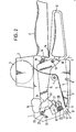
- the labeling device shown in FIG. 1 has a housing 1 to which a handle 2 is attached. On the top of the housing there is a shaft 3 for receiving a supply roll 4 of a carrier tape 5 with self-adhesive labels 6 adhering to it.
- the carrier tape 5 runs in the device from the shaft 3 first downward and then after a deflection on a roll 7 forward to a dispensing edge 8 , on which the carrier tape 5 is deflected and guided past a schematically illustrated transport device 9 to the rear end of the housing.
- a pressure roller 10 is rotatably mounted in the housing 1 about an axis 11, with which a label 6 'detached from the carrier tape 5 on the dispensing edge 8 and in the dispensing position can be glued to an object by rolling off the pressure roller 10.
- An operating lever 12 is mounted below the handle 2 and is rotatably mounted about an axis 13. Between the handle 2 and the operating lever 12 there is a spring 14 which always tries to push the operating lever 12 into the rest position shown in FIG. 1.
- a printing unit lever 15 In the housing 1 there is also a printing unit lever 15, which is also rotatably mounted about the axis 13.
- This printing unit lever 15 carries a printing unit 16, by means of which a self-adhesive label 6 located on a printing table 17 can be printed.
- a spring 19 is attached between an arm 18 of the operating lever 12 and the printing unit lever 15 and serves to transmit a movement of the operating lever 12 directed against the handle 2 to the printing unit lever 15. In the rest position shown in FIG. 1, the printing unit lever 15 is held in the raised position by a lug 20 on the operating lever 12.
- a swivel bracket 21 is rotatably mounted about an axis 22.
- a torsion spring 23 is placed, which is supported at one end on the swivel bracket and at the other end on a stop 24 fixed to the housing.
- the torsion spring 23 exerts a force on the swivel bracket 21 which attempts to rotate the swivel bracket 21 counterclockwise about the axis 22.
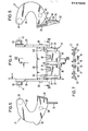
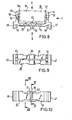
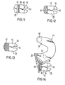
- the swivel bracket 21 carries a ink roller holder 25, which holds an ink roller 26, by means of which printing types 27 located on the lower end face of the printing unit 16 can be inked. Details of the swivel bracket 21 can be seen in FIGS. 4, 5, 6 and 7, while details of the paint roller holder can be seen in FIGS. 8 to 13.
- the swivel bracket 21 has two parallel arms 28, 29 which are connected to one another by a web 30 at one end. At the lower end of the web 30 there is a tongue 32 divided by a slot 31. The side edges of the tongue 32 are designed as guide strips 33, 34. Furthermore, two projections 35, 36 are attached adjacent to the slot 31 in the lower region of the two parts of the tongue 32. At the upper end of the tongue 32 two hooks 37, 38 are attached on both sides of the slot 31.
- journal 39, 40 At the upper ends of the arms 28, 29 there are two journals 39, 40, the axes 41, 42 of which lie on a common line. These two journals 39, 40 are used in the labeling device of FIG. 1 in recesses in the side walls of the housing 1, so that the axis 22 is fixed in this way, about which the pivot bracket 21 can be pivoted in the labeling device.
- the paint roller holder 25 shown in FIGS. 8 to 13 partly in complete views and partly in section has two arms 43, 44 which run parallel to one another and are connected to one another by a web 45.
- gripping surfaces 46, 47 are attached to the outside of the arms 43, 44, which have a corrugated surface.
- grooves 48, 49 are recessed, the shape of which is complementary to the shape of the guide strips 33, 34 of the tongue 32 on the swivel bracket 21.
- the color roller holder 25 can therefore be pushed radially from below to the pivot axis 22 over the tongue 32, the guide strips 33, 34 and the grooves 48, 49 coming into engagement.
- the web 45 has two symmetrical halves which are connected to one another by an arch-shaped bridge 50.
- the bridge 50 extends over the entire height of the web 45.
- the bridge 50 forms a predetermined kink, which causes the ends of the arms 43, 44 located at the top in FIG. 8 to spread apart when opposing compressive forces are exerted on the gripping surfaces 46, 47 will. So that the kinking of the web 45 does not go so far when the application of such pressure forces that the web 45 breaks off at the bridge 50, two limiting tabs 51, 52 are attached to the web 45 on the side facing away from the bridge 50 and extend over the entire web height that run parallel at a predetermined distance from each other. Due to the attachment of these limiting tabs 51, 52, the web 45 can only be bent by exerting pressure on the gripping surfaces 46, 47 until the limiting tabs 51, 52 touch. A further kink would only be possible by applying an excessive force.
- the paint roller 26 consists of an absorbent roller body 55, which is impregnated with a printing ink, and of two disks 56, 57 adjoining the roller body 55 laterally, from whose outer surfaces two axle journals 58, 59 protrude.
- the bearing recesses 54 are dimensioned such that they allow the ink roller 26 to rotate freely about the axle journals 58, 59.
- the axle journals 58 and 59 are securely seated in the bearing recesses 54, so that the ink roller 26 cannot fall out of the ink roller holder 25.
- the arms 43, 44 must be spread so far apart by exerting pressure on the gripping surfaces 46, 47 that the journals 58, 59 come out of engagement with the bearing recesses 54.
- the ink roller 26 then falls out of the ink roller holder 25. This procedure must be carried out if a used paint roller is to be exchanged for a new one.
- Fig. 14 shows how the ink roller holder 25 is inserted in the swivel bracket 21 and is held by the projections and hooks.
- Fig. 3 shows how the disks 56, 57 abut the housing of the printing unit 16 and keep the roller body 55 at a distance from the housing when the printing unit 16 is completely lowered onto the printing table 17.
- the swivel bracket 21 is pivoted so far that the lower end of the tongue 32 protrudes from an opening in the end face of the housing 1 of the labeling device, as shown in FIG. 3.
- the transport device 9 Via a lever connection, not shown, the transport device 9 has been moved simultaneously from the position shown in FIG. 1 in the direction of the printing table 17 along the carrier belt 5.
- the spring 14 moves the operating lever back into the starting position shown in FIG. 1, the nose 20 pivoting the printing unit lever 15 back into its shown starting position clockwise in the axis 13.
- the transport device 9 is also moved back into its starting position shown in FIG. 1; However, in this B e-movement it is fixed to the carrier tape 5 in engagement, so that this one of the length of a self- adhesive label corresponding distance is drawn around the dispensing edge 8.
- a self-adhesive label detaches from the carrier tape and comes into the position of the self-adhesive label 6 i below the pressure roller 10.
- the operator brings the swivel bracket 21 into the position shown in FIG. 3 by pulling the operating lever, in which the tongue 32 protrudes on the end face of the housing 1 of the labeling device.
- the operator can pivot the swivel bracket 21 even further out of the opening made in the front face of the housing, so that the ink roller holder 25 and the ink roller 26 are finally located outside the housing 1. So that the swivel bracket 21 remains in this pivoted position when the tongue 32 is released, the elevations 60, 61 shown in FIG.
- the swivel bracket 21 can be swiveled out of the opening on the end face of the housing 1 via the elevations 60, 61, but the force of the torsion spring 23 is not sufficient to swivel it back into the housing.
- the swivel bracket 21 thus remains in a position in which the paint roller holder 25 can be easily removed from the swivel bracket 21 for the purpose of replacing the paint roller 26.
- the ink roller holder is held on the swivel bracket 21 by the cooperation of the projections 35, 36 and the hooks 37, 38 with the web 45.
- the paint roller holder 25 is seated with a relatively large amount of play between the projections 35, 36 and the hooks 37, 38, so that it can be easily pulled down from the tongue 32 by the operator.
- the operator has the ink roller holder 25 to a little counterclockwise rotate only in the view of Fig. 14, so that the rear surface of the web arbrollenhalter 25 thus can 45 over the protrusions 35, 36 slide over and F are removed from the swivel bracket 21.
- the ink roller 26 can then be removed from the ink roller holder 25 by exerting pressure on the gripping surfaces 46, 47 and thereby spreading the arms 43, 44 and replaced with a new ink roller.
- connection between the ink roller holder 25 and the swivel bracket 21 must therefore be at least so firm that the forces that occur do not lead to the ink roller holder being released from the swivel bracket 21.
- This is mainly achieved in that the exercise of the print types 27 exerted forces and the force acting on the ink roll 26 the centrifugal force on the ink roller holder 25, a torque ig the ink roller holder 25 in the view from F. 14 tried to turn clockwise. Because of this rotation, the projections 35, 36 come into firm engagement with the web 45, so that the ink roller holder 25 is thereby securely held on the swivel bracket 21 despite its relatively loose fit.
- the swivel bracket 21 is equipped with two inclined surfaces 62, 63, of which the inclined surface 63 in FIG. 6 can be clearly recognized in its course. The end face of the printing unit 16 comes into contact with these inclined surfaces when it is lowered by actuating the operating lever 12 and the ink roller holder 25 is removed from the swivel bracket 21.
- the pivoting of the swivel bracket 21 caused by the interaction of the inclined surfaces 62, 63 with the printing unit 16 is not sufficient, however, to swivel the swivel bracket 21 to the front side of the housing 1 so that the operator can easily grasp the tongue 32.
- a stop 64 is attached to the printing unit lever 15, which comes into engagement with a nose 65 on the pivot bracket 21 when the printing unit lever 15 is lowered, so that when the printing unit lever 15 is lowered further, the pivot bracket 21 pivots out of the housing 1 as far as possible until it assumes the position shown in FIG. 3, which it would also assume if the ink roller holder 25 and the ink roller 26 were present. The operator can thereby grasp the swivel bracket 21 on the tongue 32 and bring it back into the position in which the ink roller holder 25 can be easily pushed onto the tongue 32.
- the labeling described contains an e infhausbevorraum for the printing types of the printing unit that allows a simple and convenient replacement of spent paint roller and set the ink roller carriage anyway and securely holds the swivel bracket 21 so that an unintentional release of the paint roller holder 25 excluded from the swivel bracket 21 is.
Landscapes
- Labeling Devices (AREA)
- Vending Machines For Individual Products (AREA)
Priority Applications (1)
| Application Number | Priority Date | Filing Date | Title |
|---|---|---|---|
| AT85116295T ATE53807T1 (de) | 1985-01-10 | 1985-12-19 | Etikettiergeraet. |
Applications Claiming Priority (2)
| Application Number | Priority Date | Filing Date | Title |
|---|---|---|---|
| DE3500656 | 1985-01-10 | ||
| DE19853500656 DE3500656A1 (de) | 1985-01-10 | 1985-01-10 | Etikettiergeraet |
Publications (2)
| Publication Number | Publication Date |
|---|---|
| EP0187986A1 true EP0187986A1 (fr) | 1986-07-23 |
| EP0187986B1 EP0187986B1 (fr) | 1990-05-02 |
Family
ID=6259571
Family Applications (1)
| Application Number | Title | Priority Date | Filing Date |
|---|---|---|---|
| EP85116295A Expired - Lifetime EP0187986B1 (fr) | 1985-01-10 | 1985-12-19 | Dispositif d'étiquetage |
Country Status (5)
| Country | Link |
|---|---|
| US (1) | US4724034A (fr) |
| EP (1) | EP0187986B1 (fr) |
| JP (1) | JPS61217336A (fr) |
| AT (1) | ATE53807T1 (fr) |
| DE (2) | DE3500656A1 (fr) |
Cited By (4)
| Publication number | Priority date | Publication date | Assignee | Title |
|---|---|---|---|---|
| EP0286997A3 (en) * | 1987-04-16 | 1989-04-26 | Klaus-Dieter Hermann | Hand labeller |
| WO1991000218A1 (fr) * | 1989-07-01 | 1991-01-10 | Hermann Klaus D | Agencement pour l'impression de bandes d'etiquettes |
| DE19848977A1 (de) * | 1998-10-23 | 2000-04-27 | Meto International Gmbh | Etikettiergerät |
| DE19848976A1 (de) * | 1998-10-23 | 2000-04-27 | Meto International Gmbh | Etikettiergerät |
Families Citing this family (7)
| Publication number | Priority date | Publication date | Assignee | Title |
|---|---|---|---|---|
| DE3706433A1 (de) * | 1987-02-27 | 1988-09-08 | Esselte Meto Int Gmbh | Handetikettiergeraet |
| DE3706439C1 (de) * | 1987-02-27 | 1988-06-23 | Esselte Meto Internat Gmbh | Handetikettiergeraet |
| US5254206A (en) * | 1992-01-31 | 1993-10-19 | Wing Donald B | Hand-held labeling device |
| USD365597S (en) | 1993-04-22 | 1995-12-26 | Esselte Meto International Produktions Gmbh | Hand held labeler |
| US6138734A (en) * | 1995-01-12 | 2000-10-31 | Monarch Marking Systems, Inc. | Hand-held labeler and method of making same |
| US6766842B1 (en) * | 1996-08-22 | 2004-07-27 | Paxar Americas, Inc. | Hand-held labeler |
| EP0919503B1 (fr) * | 1997-11-24 | 2001-08-29 | Roberto Orlandi | Appareil pour appliquer un ruban adhésif comprenant systèmes d'impression pour imprimer sur la surface extérieure du ruban |
Citations (3)
| Publication number | Priority date | Publication date | Assignee | Title |
|---|---|---|---|---|
| US3817177A (en) * | 1973-05-07 | 1974-06-18 | Avery Products Corp | Hand labeler |
| DE2502108A1 (de) * | 1975-01-20 | 1976-07-22 | Sato Kenkyusho Setagaya Kk | Handetikettiergeraet mit unterschlag-einfaerbevorrichtung |
| US4273046A (en) * | 1979-06-18 | 1981-06-16 | Kabushiki Kaisha Sato Kenkyusho | Attaching mechanism for inking device of portable label printing machine or the like |
Family Cites Families (10)
| Publication number | Priority date | Publication date | Assignee | Title |
|---|---|---|---|---|
| US3759178A (en) * | 1971-02-03 | 1973-09-18 | Pitney Bowes Inc | Inking roller assembly |
| US4216715A (en) * | 1975-01-09 | 1980-08-12 | Kabushiki Kaisha Sato Kenkyusho | Cartridge-type ink supply device for labeling machines |
| DE2618502A1 (de) * | 1975-04-28 | 1976-11-18 | Sato Kenkyusho | Farbstoff-zufuehreinrichtung fuer tragbare etikettiergeraete |
| US4044677A (en) * | 1975-08-13 | 1977-08-30 | Monarch Marking Systems, Inc. | Inking mechanism |
| JPS5226917A (en) * | 1975-08-26 | 1977-02-28 | Sato Kenkyusho | Device for supplying ink to label printing labeler or the like |
| JPS5244598A (en) * | 1975-10-07 | 1977-04-07 | Sato Kenkyusho:Kk | Ink supply equipment for label printer/sticker |
| JPS5327644A (en) * | 1976-08-27 | 1978-03-15 | Gunei Kagaku Kogyo Kk | Selffemulsifiable phenolic resin compound |
| CA1093383A (fr) * | 1976-09-06 | 1981-01-13 | Yo Sato | Dispositif d'alimentation en encre pour etiqueteuse manuelle |
| US4252060A (en) * | 1979-04-23 | 1981-02-24 | Monarch Marking Systems, Inc. | Label printing apparatus |
| US4359939A (en) * | 1981-04-21 | 1982-11-23 | Kabushiki Kaisha Sato Kenkyusho | Printing device |
-
1985
- 1985-01-10 DE DE19853500656 patent/DE3500656A1/de active Granted
- 1985-12-19 EP EP85116295A patent/EP0187986B1/fr not_active Expired - Lifetime
- 1985-12-19 AT AT85116295T patent/ATE53807T1/de not_active IP Right Cessation
- 1985-12-19 DE DE8585116295T patent/DE3577428D1/de not_active Expired - Lifetime
-
1986
- 1986-01-07 US US06/816,855 patent/US4724034A/en not_active Expired - Lifetime
- 1986-01-10 JP JP61003380A patent/JPS61217336A/ja active Granted
Patent Citations (3)
| Publication number | Priority date | Publication date | Assignee | Title |
|---|---|---|---|---|
| US3817177A (en) * | 1973-05-07 | 1974-06-18 | Avery Products Corp | Hand labeler |
| DE2502108A1 (de) * | 1975-01-20 | 1976-07-22 | Sato Kenkyusho Setagaya Kk | Handetikettiergeraet mit unterschlag-einfaerbevorrichtung |
| US4273046A (en) * | 1979-06-18 | 1981-06-16 | Kabushiki Kaisha Sato Kenkyusho | Attaching mechanism for inking device of portable label printing machine or the like |
Cited By (6)
| Publication number | Priority date | Publication date | Assignee | Title |
|---|---|---|---|---|
| EP0286997A3 (en) * | 1987-04-16 | 1989-04-26 | Klaus-Dieter Hermann | Hand labeller |
| WO1991000218A1 (fr) * | 1989-07-01 | 1991-01-10 | Hermann Klaus D | Agencement pour l'impression de bandes d'etiquettes |
| DE19848977A1 (de) * | 1998-10-23 | 2000-04-27 | Meto International Gmbh | Etikettiergerät |
| DE19848976A1 (de) * | 1998-10-23 | 2000-04-27 | Meto International Gmbh | Etikettiergerät |
| DE19848977B4 (de) * | 1998-10-23 | 2004-04-08 | Meto International Gmbh | Etikettiergerät |
| DE19848976B4 (de) * | 1998-10-23 | 2006-02-23 | Meto International Gmbh | Etikettiergerät |
Also Published As
| Publication number | Publication date |
|---|---|
| DE3500656C2 (fr) | 1987-10-08 |
| US4724034A (en) | 1988-02-09 |
| DE3500656A1 (de) | 1986-07-10 |
| DE3577428D1 (de) | 1990-06-07 |
| JPH021744B2 (fr) | 1990-01-12 |
| EP0187986B1 (fr) | 1990-05-02 |
| ATE53807T1 (de) | 1990-06-15 |
| JPS61217336A (ja) | 1986-09-26 |
Similar Documents
| Publication | Publication Date | Title |
|---|---|---|
| DE2857834C2 (de) | Handetikettiergeraet | |
| EP0039803B1 (fr) | Etiqueteuse à main | |
| DE2734334C2 (de) | Leiteinrichtung für ein Etikettenband in einem Handetikettiergerät | |
| EP0187986B1 (fr) | Dispositif d'étiquetage | |
| DE3403103C2 (de) | Vorrichtung zur Verriegelung eines Stiftteils in einer Anschlußbüchse eines Befestigungselements | |
| DE3907716C2 (fr) | ||
| DE2831319A1 (de) | Handgeraet zum drucken und aufbringen von druckempfindlichen etiketten | |
| DE2901696C2 (de) | Handetikettiergerät zum Bedrucken, Ausgeben und Anbringen von Selbstklebeetiketten | |
| DE3706433C2 (fr) | ||
| EP0035240B1 (fr) | Dispositif d'impression | |
| DE2518782C3 (de) | Gerät zum Bedrucken, Ausgeben und Anbringen von selbsthaftenden Etiketten | |
| EP0284721B1 (fr) | Etiqueteuse à main | |
| DE3711960C2 (de) | Handetikettiergerät | |
| DE2502108C3 (de) | Unterschlag-Einfärbevorrichtung für das Druckwerk eines Handetikettiergerätes | |
| EP0039781B1 (fr) | Appareil d'impression et de distribution d'étiquettes autocollantes portées par une bande support | |
| EP0200031B1 (fr) | Rouleau presseur pour dispositif d'étiquetage | |
| DE3618908C2 (fr) | ||
| DE3130378C2 (de) | Gerät zum Bedrucken und Ausgeben von auf einem Trägerband haftenden Selbstklebeetiketten | |
| DE2923164C2 (fr) | ||
| DE2916549A1 (de) | Vorrichtung zum einfuehren eines etikettenbandes | |
| DE3302437C2 (de) | Handetikettiergerät | |
| DE1924023C3 (de) | Handetikettiergerat | |
| EP0074980B1 (fr) | Ouvre-boite avec pince de maintien | |
| DE2639810B2 (de) | Verfahren und Vorrichtung zum Abziehen eines Materialbahnabschnittes vorgegebener Länge von einer Vorratsrolle | |
| DE3033572C1 (de) | Vorrichtung zur Aufnahme einer Tintenrolle |
Legal Events
| Date | Code | Title | Description |
|---|---|---|---|
| PUAI | Public reference made under article 153(3) epc to a published international application that has entered the european phase |
Free format text: ORIGINAL CODE: 0009012 |
|
| AK | Designated contracting states |
Kind code of ref document: A1 Designated state(s): AT DE FR GB NL SE |
|
| 17P | Request for examination filed |
Effective date: 19860912 |
|
| 17Q | First examination report despatched |
Effective date: 19870331 |
|
| RAP1 | Party data changed (applicant data changed or rights of an application transferred) |
Owner name: ESSELTE METO INTERNATIONAL PRODUKTIONS GMBH |
|
| 111L | Licence recorded |
Free format text: 0100 ESSELTE METO, S.N.C. |
|
| GRAA | (expected) grant |
Free format text: ORIGINAL CODE: 0009210 |
|
| AK | Designated contracting states |
Kind code of ref document: B1 Designated state(s): AT DE FR GB NL SE |
|
| REF | Corresponds to: |
Ref document number: 53807 Country of ref document: AT Date of ref document: 19900615 Kind code of ref document: T |
|
| ET | Fr: translation filed | ||
| GBT | Gb: translation of ep patent filed (gb section 77(6)(a)/1977) | ||
| REF | Corresponds to: |
Ref document number: 3577428 Country of ref document: DE Date of ref document: 19900607 |
|
| PLBE | No opposition filed within time limit |
Free format text: ORIGINAL CODE: 0009261 |
|
| STAA | Information on the status of an ep patent application or granted ep patent |
Free format text: STATUS: NO OPPOSITION FILED WITHIN TIME LIMIT |
|
| 26N | No opposition filed | ||
| PGFP | Annual fee paid to national office [announced via postgrant information from national office to epo] |
Ref country code: SE Payment date: 19911030 Year of fee payment: 7 |
|
| PGFP | Annual fee paid to national office [announced via postgrant information from national office to epo] |
Ref country code: AT Payment date: 19911210 Year of fee payment: 7 |
|
| PGFP | Annual fee paid to national office [announced via postgrant information from national office to epo] |
Ref country code: NL Payment date: 19911231 Year of fee payment: 7 |
|
| PG25 | Lapsed in a contracting state [announced via postgrant information from national office to epo] |
Ref country code: AT Effective date: 19921219 |
|
| PG25 | Lapsed in a contracting state [announced via postgrant information from national office to epo] |
Ref country code: SE Effective date: 19921220 |
|
| REG | Reference to a national code |
Ref country code: FR Ref legal event code: CL |
|
| PG25 | Lapsed in a contracting state [announced via postgrant information from national office to epo] |
Ref country code: NL Effective date: 19930701 |
|
| NLV4 | Nl: lapsed or anulled due to non-payment of the annual fee | ||
| EUG | Se: european patent has lapsed |
Ref document number: 85116295.8 Effective date: 19930709 |
|
| REG | Reference to a national code |
Ref country code: GB Ref legal event code: IF02 |
|
| PGFP | Annual fee paid to national office [announced via postgrant information from national office to epo] |
Ref country code: FR Payment date: 20021210 Year of fee payment: 18 |
|
| PGFP | Annual fee paid to national office [announced via postgrant information from national office to epo] |
Ref country code: GB Payment date: 20021218 Year of fee payment: 18 |
|
| PGFP | Annual fee paid to national office [announced via postgrant information from national office to epo] |
Ref country code: DE Payment date: 20021219 Year of fee payment: 18 |
|
| PG25 | Lapsed in a contracting state [announced via postgrant information from national office to epo] |
Ref country code: GB Free format text: LAPSE BECAUSE OF NON-PAYMENT OF DUE FEES Effective date: 20031219 |
|
| PG25 | Lapsed in a contracting state [announced via postgrant information from national office to epo] |
Ref country code: DE Free format text: LAPSE BECAUSE OF NON-PAYMENT OF DUE FEES Effective date: 20040701 |
|
| GBPC | Gb: european patent ceased through non-payment of renewal fee |
Effective date: 20031219 |
|
| PG25 | Lapsed in a contracting state [announced via postgrant information from national office to epo] |
Ref country code: FR Free format text: LAPSE BECAUSE OF NON-PAYMENT OF DUE FEES Effective date: 20040831 |
|
| REG | Reference to a national code |
Ref country code: FR Ref legal event code: ST |