EP0188089A2 - Verkaufsschaustellungsvorrichtung - Google Patents
Verkaufsschaustellungsvorrichtung Download PDFInfo
- Publication number
- EP0188089A2 EP0188089A2 EP85309009A EP85309009A EP0188089A2 EP 0188089 A2 EP0188089 A2 EP 0188089A2 EP 85309009 A EP85309009 A EP 85309009A EP 85309009 A EP85309009 A EP 85309009A EP 0188089 A2 EP0188089 A2 EP 0188089A2
- Authority
- EP
- European Patent Office
- Prior art keywords
- box
- wall
- panel
- sales display
- sales
- Prior art date
- Legal status (The legal status is an assumption and is not a legal conclusion. Google has not performed a legal analysis and makes no representation as to the accuracy of the status listed.)
- Withdrawn
Links
Images

Classifications
-
- B—PERFORMING OPERATIONS; TRANSPORTING
- B65—CONVEYING; PACKING; STORING; HANDLING THIN OR FILAMENTARY MATERIAL
- B65D—CONTAINERS FOR STORAGE OR TRANSPORT OF ARTICLES OR MATERIALS, e.g. BAGS, BARRELS, BOTTLES, BOXES, CANS, CARTONS, CRATES, DRUMS, JARS, TANKS, HOPPERS, FORWARDING CONTAINERS; ACCESSORIES, CLOSURES, OR FITTINGS THEREFOR; PACKAGING ELEMENTS; PACKAGES
- B65D15/00—Containers having bodies formed by interconnecting or uniting two or more rigid, or substantially rigid, sections made of different materials
- B65D15/22—Containers having bodies formed by interconnecting or uniting two or more rigid, or substantially rigid, sections made of different materials of polygonal cross-section
-
- B—PERFORMING OPERATIONS; TRANSPORTING
- B65—CONVEYING; PACKING; STORING; HANDLING THIN OR FILAMENTARY MATERIAL
- B65D—CONTAINERS FOR STORAGE OR TRANSPORT OF ARTICLES OR MATERIALS, e.g. BAGS, BARRELS, BOTTLES, BOXES, CANS, CARTONS, CRATES, DRUMS, JARS, TANKS, HOPPERS, FORWARDING CONTAINERS; ACCESSORIES, CLOSURES, OR FITTINGS THEREFOR; PACKAGING ELEMENTS; PACKAGES
- B65D5/00—Rigid or semi-rigid containers of polygonal cross-section, e.g. boxes, cartons or trays, formed by folding or erecting one or more blanks made of paper
- B65D5/42—Details of containers or of foldable or erectable container blanks
- B65D5/44—Integral, inserted or attached portions forming internal or external fittings
- B65D5/441—Reinforcements
- B65D5/445—Reinforcements formed separately from the container
-
- B—PERFORMING OPERATIONS; TRANSPORTING
- B65—CONVEYING; PACKING; STORING; HANDLING THIN OR FILAMENTARY MATERIAL
- B65D—CONTAINERS FOR STORAGE OR TRANSPORT OF ARTICLES OR MATERIALS, e.g. BAGS, BARRELS, BOTTLES, BOXES, CANS, CARTONS, CRATES, DRUMS, JARS, TANKS, HOPPERS, FORWARDING CONTAINERS; ACCESSORIES, CLOSURES, OR FITTINGS THEREFOR; PACKAGING ELEMENTS; PACKAGES
- B65D5/00—Rigid or semi-rigid containers of polygonal cross-section, e.g. boxes, cartons or trays, formed by folding or erecting one or more blanks made of paper
- B65D5/42—Details of containers or of foldable or erectable container blanks
- B65D5/44—Integral, inserted or attached portions forming internal or external fittings
- B65D5/52—External stands or display elements for contents
Definitions
- This invention relates to merchanidising equipment and is concerned in particular with sales display devices for use in connection with the display and sale of articles.
- the sales display devices of the invention improve both the usefulness and the appearance of containers holding articles.
- An example of the kinds of articles, packaged in containers, with which the invention is especially beneficial is bags of snackfoods.
- a very wide variety of snackfoods such as nuts, potato crisps, potato rings and other potato- based and cereal-based snack products, are commonly put up for sale in bags. Substantial quantities of these bags of snack-foods are displayed for sale in retail premises, such as supermarkets, shops in the grocery, confectionery and allied trades and in off-licences and public houses.
- retail premises such as supermarkets, shops in the grocery, confectionery and allied trades and in off-licences and public houses.
- the containers in which the bags of snackfoods are packaged are usually cartons or cardboard cases.
- boxes these and any other kind of container, with which a sales display device of the invention can be used, is referred to below as a "box"; this term is to be understood as thus having this very wide meaning, in this context.
- the boxes used for this purpose are usually conventional rectangular cardboard boxes, having four upright wall panels forming two long side walls and two short sides or end walls, which are connected together at the corners of the case. These side and end walls have closure flaps for the case attached to their bottom and top edges.
- the bottom flaps are closed to make the base of the box, the contents are put in and the top flaps are then closed.
- one common practice is to provide a circular, rectangular or other panel, for instance in one end wall, and this panel is defined for instance by means of one or more lines of perforations. This panel can easily be removed, by separating the material of the box at the perforations, so that the bags can then be readily taken from the box by customers, as they pass the area where the boxes are displayed and so can select the number of bags required.
- the devices of the invention enable the particular kinds of products to be indicated more clearly, they enable the sales price to be changed readily, if desired, and also they provide larger openings for access to the contents of the boxes than is generally possible under the present practice.
- the expression "access aperture” is used to mean the hole in the box and the expression “access opening” is used to mean the hole in the sales display device, by which articles in the prepared box can be taken out of it.
- a sales display device for use in association with a box having a wall containing a removable panel, which comprises a mask having a size and shape so that it can fit over such wall of the box and including a peripheral frame defining an opening giving access to the interior of the box, through the aperture formed by removing the panel from the box wall, t when the device is fitted over such wall.
- the frame conceals the edges of the aperture in the box, when the device is fitted over such wall.
- the edges concealed by the frame, in use of the device most preferably are those which at least partly coincide with the edges of panels adjacent the box wall containing the removable panel.
- the sales display device of the invention is a one-piece plastics moulding or vacuum-formed article.
- the sales display device includes a display panel, for instance for the receipt and indication of information. It is preferable, in accordance with this embodiment of the invention, for the access opening to comprise from half to three-quarters of the area of the box wall fitted with the device in use and the display panel comprises the remainder of such area.
- the access opening advantageously comprises the upper part of the mask and the display panel comprises its lower part.
- the device is of approximately the same shape overall as the end of the related box and of slightly larger dimensions, so that it can fit over that end.
- the sales display device of the invention includes, along at least part of its periphery, a rearwardly-open channel, comprising an outer wall part and an inner wall part, which in use are respectively located outside the box wall and inside the edges of the aperture.
- This channel formation can conveniently be disposed along at least a major part of the periphery of the device, corresponding for instance to the edges of an end wall of the box, and within this frame the device defines an access opening, which typically is equivalent in area to half, two-thirds or even as much as three-quarters of the whole area of the end wall of the box.
- a substantial part or even the whole of the end wall panel is preferably made easily removable, for instance by being defined by lines of perforations made in the box material. These lines may extend along the upper edge and along substantial lengths of the two opposed side edges of the end or side wall or panel, with a lower line of perforations joining these side edges.
- the mask is preferably shaped to fit over an entire wall of the box, e.g. its entire end or side wall, with the interior part of the frame, defining the access opening, fitting inside the access aperture formed in the side or end wall of the box when the panel has been removed.
- a method for preparing a box of articles for display and sale of the articles such box having a wall containing a removable panel, which comprises removing the panel, fitting a sales display device over such wall of the box, the device including a peripheral frame defining an opening giving access to the interior of the box through the aperture formed by removing the panel, and displaying the assembled box and device so that the wall fitted with the device is visible and accessible.
- the invention resides in a kit of sales display devices, for use in association with boxes having a removable panel either in an end or side wall or in a top wall or having an openable top, which comprises at least one first sales display device for association with the end or side wall of one of the boxes and at least one second sales display device comprising a rearwardly-open tray for receiving the base of a top-opening box.
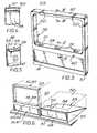
- the sales display device of the embodiment of the invention shown in Figs. 1 and 2, indicated generally at 10, is intended to be used with a typical rectangular cardboard box or case, an end portion of which is indicated generally at 11 in Fig. 2.
- the box 11 consists of an opposed pair of side walls 12 joined by a corresponding opposed pair of end walls (only the lower part of one of which is shown at 14 in Fig. 2), these side and end walls 12,14 typically being joined at each of the resultant four upright corners of the box, the join at one of the corners usually involving gluing and/or stitching, as is well known in the cardboard box art.
- the top and bottom of the box 11 are closed by interengaging flaps in conventional fashion, parts of the top and bottom wall panels of the box 11, formed from such flaps, being indicated at 15 and 16 respectively in Fig. 2.
- the box 11 is filled with articles, such as bags of a snackfood, for instance 48 1-ounce (28 gm) bags of potato crisps.
- Information about the contents of the box, such as the flavour, bag weight and other details of the snackfood, is indicated in a bold fashion on the outside surfaces of the box 11.
- One of the walls of the box 11, for instance, an end wall typically, is provided with a large and readily- removable panel, not shown in Fig.
- the lines of perforations in the box and thus included in the blank from which it was made can typically be located along the fold lines which join adjacent panels together, except perhaps for the line of perforations on one side of the panel, as is shown in effect in Fig. 2; thus, removal of the panel defined by these lines exposes the edge or thickness of the cardboard or other sheet material along at least some of the sides of the resultant access aperture.
- These edges are shown at 25 for parts of the side panels 12 and at 26 for the top panel 15.
- the edge or thickness of the cardboard or other material is also exposed, e.g. as shown at 27 for the end panel 14, where part of the end panel is not included in the removable panel.
- the sales display device 10 consists of a generally rectangular mask-like one-piece plastics moulding or vacuum-formed article, which has a frame-like outer wall part 17 extending rearwardly from the rectangular periphery of the sales display device 10 and thus from a plane representing the front surface of the device 10.
- the wall part 17 is intended to fit over and around the exterior of the end of the box 11 and so completely conceals or masks the parts of the side walls 12 and the top and bottom of the box 11 adjacent the end wall with the removable panel, i.e. the parts immediately adjacent the edges 25 and 26 around the access aperture formed on removal of the panel.
- the removable panel i.e. the parts immediately adjacent the edges 25 and 26 around the access aperture formed on removal of the panel.
- the wall part 17 is associated with a corresponding internal wall part 18, so that these wall parts 17 and 18 of the mask 10 consist of a rearwardly-open and divergent U-shaped channel, as indicated most clearly at the top in Fig. 1.
- the channel comprising the wall part 18 and the associated portions of the wall part 17 thus defines a generally rectangular access opening of substantial size, which preferably corresponds very closely in size and shape to the access aperture formed in the end of the box 11 by removing the removable panel. It will be appreciated that a mask 10 could be used with a box 11 having an access aperture larger than the access opening in the mask 10, so that the same mask could be used with boxes having different sizes or shapes of access apertures, if desired or necessary.
- the sales device 10 includes a further internal wall 19, which in use is located above and immediately adjacent the edge 27 and so completes the interior of the frame around the access opening in the device 10, by forming its lowest part.
- the sales device 10 includes a rectangular panel-like area 20, which preferably includes a recessed region 21, for receiving a self-adhesive indicator panel, such as a price ticket or label which can typically be supplied to retail premises with the box and the sales device 10 and can form part of a kit of sales display device components.
- a delivery of a range of boxes of snackfoods e.g. to a supermarket, will include the corresponding sales devices 10 and the indicator panels and other items associated with them.
- the access aperture In order to prepare a box for display for retail purposes, it is merely necessary to form the access aperture by removing the prepared panel, by separating it from the rest of the box along the lines of perforations, and then to fit the corresponding sales device or mask 10 into place over the thus- prepared wall panel of the box 11, as indicated in Fig. 2.
- the rectangular frame formed i.a. by the wall parts 17 thus surrounds the end of the box 11 and the internal wall parts 18 and 19 define the access opening and also form a frame or lining for the access aperture, in which the bags of snackfoods are thus displayed and are readily available for removal.
- One or more labels appropriate to the particular snackfood in the box 11 are then applied to the recessed area 21 and, if required, the appropriate self-adhesive price ticket is then attached to the label. It is found that the U-shaped configuration of the wall parts 17, 18, 19, with the preferred tapering configuration of the channel between the wall parts 17 and 18, can be sufficient to ensure that the sales device 10 will remain in place while the bags are removed, as may occur over a period of time until the box 11 is empty. This can be achieved simply, by matching the cross-section of the channel between the wall parts 17 and 18 to the thickness or gauge of the cardboard or other sheet material, so that the latter fits tightly in the U-profile of the channel.
- the sales device 10 is provided with means which give a positive engagement or interlock between the prepared end or other wall of a box, i.e. which has been opened by removal of a panel to form the access aperture, and the corresponding mask-like sales display device of the invention.
- the positive engagement or interlock means can take the form, for instance, of appropriately-directed projections, located at spaced points around the external wall part 17 and/or the internal wall parts 18 or 19. These projections, such as the projections or pips shown at 22 in the wall part 17 or at 23 in the wall part 18 in Fig. 1, can be so arranged as to press against the material of the box, which thus enables the mask 10 to grip the underlying parts of the box 11.
- a further possibility is to arrange the projections so that they can engage with corresponding depressions or apertures formed in the parts of the box 11 which are covered by the wall parts 17 and/or 18 when the device 10 is fitted into place.
- Another possible form of positive interlock is given by downwardly-directed projections, shown at 24 in Fig. 1, provided in the wall part 19, which snap behind the upstanding edge of a box wall, e.g. the wall panel 14, when the mask 10 is pressed into place over the end of the box 11.
- the sales device or mask shown in Figs. 3, 4 and 5 is indicated at 30 and likewise consists of a one- .piece article, such as a plastics moulding or a vacuum-formed plastics article.
- a large access opening in the upper part of the mask 30 is defined by internal wall parts 38 which, with external wall parts 37, form a rearwardly-open U-shaped channel.
- the mask 30 includes a rearwardly-directed internal wall part 39 and below this, i.e. between the wall parts 37 and 39, the mask 30 includes a display panel 40, preferably incorporating a recessed portion 41.
- the rearwardly-open U-shaped channel defined by the wall parts 37 and 38 incudes one or more inwardly- directed projections 50. Each of these is directed inwardly, in the sense that it reduces in its locality the cross-sectional width of the interior of the channel.
- the projections 50 in the wall part 37 are thus made inwardly towards the access opening, while the projections 50 in the wall part 38 are made inwardly of the channel and are therefore directed away from the access opening.
- at least three of the projections 50 are provided along each side of the access opening, which is rectangular as shown in Fig. 3, there being two spaced projections 50 in the respective portion of the outer wall part 37 and a central projection 50 in the associated part of the inner wall part 38.
- the projections 50 When the mask 30 is fitted over the end of a box, the projections 50 reduce the effective width of the rearwardly-open channel and firmly engage the edge of the cardboard or other material forming the side walls and top of the case, from which a panel has been removed to form the access aperture in the case. This material does not need to be selected so as to have a gauge or thickness which is accurately matched to the dimensions of the channel, as the projections 50 ensure a tight fit over a wide range of sheet material thicknesses.
- Each of the projections 50 preferably consists of a part-circular U-shaped channel, shown in more detail in cross-section in Fig. 4.
- the rearwardly-directed wall part 39 forming the lower periphery of the access opening is provided with one or more and preferably, as shown in Fig. 3, three downwardly-directed projections 51.
- Each of these can consist of a major rectangular area having a greater inclination from rear to front than the associated portions of the wall part 39, to which they are connected by side webs, as indicated in Fig. 5 at 58 and 59 respectively.
- the present invention also provides a form of sales display device for use with boxes such as cardboard or other cartons or cases which either are not suitable for the inclusion of a removable access panel, i.e. in an end or side wall, or which have such a panel in the top or have any desired form of openable top. It is nevertheless desirable for such boxes to have an integrated appearance and means of use in association with boxes which are suitable for use with the above- described sales display devices of the invention, embodiments of which are illustrated in relation to the masks 10 and 30 described above.
- the associated sales display device consists preferably of a rearwardly-open tray, shown in Fig. 6 at 53, and, like the masks 10 and 30, preferably comprising a one-piece plastics moulding or vacuum-formed plastics article.
- the tray 53 preferably consists of a rectangular base 54, sized to accommodate the base of a box 52, an upstanding front panel 56, preferably having a recessed panel portion 57 and generally corresponding in function and appearance to the lower part of the sales display device or masks 10,30 with their recessed panel portions 21 or 41, and, joining the side edges of the base 54 to the side edges of the upstanding panel 56, triangular side panels 55.
- the various sales display articles of the invention allow better display and use of cartons and cases of all kinds, whether or not they include removable access panels, and they also ensure that an integrated display of a plurality of such cases can be maintained to a higher and more satisfactory standard and ensure a substantially improved appearance for sales displays equipped with these devices.
- they can form, for instance in conjunction with suitable labels and/or price tickets, a set or kit of sales display devices for use with two or more different types of boxes.
- a kit of parts can consist of one or more filled boxes having removable panels producing access apertures in one of' their upright walls when standing, normally on their bases, most probably in an end wall and one or more other filled boxes having removable or openable top panels.
Landscapes
- Engineering & Computer Science (AREA)
- Mechanical Engineering (AREA)
- Cartons (AREA)
- Details Of Rigid Or Semi-Rigid Containers (AREA)
- Control Of Vending Devices And Auxiliary Devices For Vending Devices (AREA)
Applications Claiming Priority (4)
| Application Number | Priority Date | Filing Date | Title |
|---|---|---|---|
| GB858500328A GB8500328D0 (en) | 1985-01-07 | 1985-01-07 | Sales display device |
| GB8500328 | 1985-01-07 | ||
| GB8519690 | 1985-08-06 | ||
| GB858519690A GB8519690D0 (en) | 1985-08-06 | 1985-08-06 | Sales display device |
Publications (2)
| Publication Number | Publication Date |
|---|---|
| EP0188089A2 true EP0188089A2 (de) | 1986-07-23 |
| EP0188089A3 EP0188089A3 (de) | 1987-11-11 |
Family
ID=26288643
Family Applications (1)
| Application Number | Title | Priority Date | Filing Date |
|---|---|---|---|
| EP85309009A Withdrawn EP0188089A3 (de) | 1985-01-07 | 1985-12-11 | Verkaufsschaustellungsvorrichtung |
Country Status (2)
| Country | Link |
|---|---|
| EP (1) | EP0188089A3 (de) |
| GB (1) | GB2169432A (de) |
Families Citing this family (1)
| Publication number | Priority date | Publication date | Assignee | Title |
|---|---|---|---|---|
| IE912672A1 (en) * | 1991-07-30 | 1993-02-10 | H B Ice Cream Ltd | A Display Unit |
Family Cites Families (9)
| Publication number | Priority date | Publication date | Assignee | Title |
|---|---|---|---|---|
| GB339069A (en) * | 1929-10-31 | 1930-12-04 | Thomas James Sims | Improvements in boxes for laundry use |
| GB452120A (en) * | 1935-02-15 | 1936-08-17 | Reckitt & Sons Ltd | Improvements in and relating to counter display cards |
| BE794496A (fr) * | 1972-02-08 | 1973-05-16 | Ferrero Gmbh | Emballage de transport et de presentation pour objets en forme de plaques |
| US3836044A (en) * | 1972-07-28 | 1974-09-17 | Rapid American Corp | Bulk package incorporating movable dispenser insert for individual dispensing of substantially wet sheets from stack |
| FR2298487A1 (fr) * | 1975-01-22 | 1976-08-20 | Sauterot Drac | Boite presentoir |
| GB1562320A (en) * | 1976-11-25 | 1980-03-12 | Kerwin F | Display device |
| US4127228A (en) * | 1977-08-04 | 1978-11-28 | Willamette Industries, Inc. | Asparagus box |
| US4239306A (en) * | 1978-11-27 | 1980-12-16 | Fellowes Manufacturing Company | File frame |
| DE3202129A1 (de) * | 1982-01-23 | 1983-07-28 | Henkel KGaA, 4000 Düsseldorf | Faltschachtel |
-
1985
- 1985-11-25 GB GB08528963A patent/GB2169432A/en not_active Withdrawn
- 1985-12-11 EP EP85309009A patent/EP0188089A3/de not_active Withdrawn
Also Published As
| Publication number | Publication date |
|---|---|
| EP0188089A3 (de) | 1987-11-11 |
| GB2169432A (en) | 1986-07-09 |
| GB8528963D0 (en) | 1986-01-02 |
Similar Documents
| Publication | Publication Date | Title |
|---|---|---|
| US6401932B1 (en) | Handleset packaging with interactive feature | |
| US4925087A (en) | Packaging container with display window | |
| US4312451A (en) | Self standing flanged tray with integral lid | |
| US5888565A (en) | Food package including a tray with cover member having a raised top surface | |
| US4724964A (en) | Reusable plastic container mounted to backing board | |
| US4116330A (en) | Combination package and display case | |
| US5485919A (en) | Clamshell package and packaging system | |
| US7681733B2 (en) | Packaging container with criss-cross grain pattern having product holding chambers and method for making the same | |
| US5251972A (en) | Device for displaying and dispensing consumer products on shelving | |
| US4307806A (en) | Integral foldable package | |
| US4042110A (en) | Carton display device | |
| US4925088A (en) | Packaging container | |
| US4955469A (en) | Convertible container | |
| US6199692B1 (en) | Reduced material box design for round objects | |
| US5291995A (en) | Pack for notions and the like | |
| US6837379B2 (en) | Display box | |
| US6886737B2 (en) | Point-of-purchase display with indicia panel | |
| US5762203A (en) | Container for shipping and displaying of product | |
| US4484681A (en) | Package for carded merchandise | |
| EP0188089A2 (de) | Verkaufsschaustellungsvorrichtung | |
| US7328552B2 (en) | Method of packaging articles for shipment, storage and display | |
| JP3023325B2 (ja) | 容 器 | |
| EP1194335B1 (de) | Warenschaudose und spender | |
| GB2141102A (en) | Packaging system | |
| JPH0452791Y2 (de) |
Legal Events
| Date | Code | Title | Description |
|---|---|---|---|
| PUAI | Public reference made under article 153(3) epc to a published international application that has entered the european phase |
Free format text: ORIGINAL CODE: 0009012 |
|
| AK | Designated contracting states |
Kind code of ref document: A2 Designated state(s): AT BE CH DE FR IT LI LU NL SE |
|
| PUAL | Search report despatched |
Free format text: ORIGINAL CODE: 0009013 |
|
| AK | Designated contracting states |
Kind code of ref document: A3 Designated state(s): AT BE CH DE FR IT LI LU NL SE |
|
| STAA | Information on the status of an ep patent application or granted ep patent |
Free format text: STATUS: THE APPLICATION IS DEEMED TO BE WITHDRAWN |
|
| 18D | Application deemed to be withdrawn |
Effective date: 19880705 |
|
| RIN1 | Information on inventor provided before grant (corrected) |
Inventor name: MARTIN, CHARLES MALCOLM |