EP0188096B1 - Assemblage semi-rigide de modules photovoltaiques et support de montage pour celui-ci - Google Patents
Assemblage semi-rigide de modules photovoltaiques et support de montage pour celui-ci Download PDFInfo
- Publication number
- EP0188096B1 EP0188096B1 EP85309055A EP85309055A EP0188096B1 EP 0188096 B1 EP0188096 B1 EP 0188096B1 EP 85309055 A EP85309055 A EP 85309055A EP 85309055 A EP85309055 A EP 85309055A EP 0188096 B1 EP0188096 B1 EP 0188096B1
- Authority
- EP
- European Patent Office
- Prior art keywords
- semirigid
- photovoltaic module
- support member
- accordance
- support
- Prior art date
- Legal status (The legal status is an assumption and is not a legal conclusion. Google has not performed a legal analysis and makes no representation as to the accuracy of the status listed.)
- Expired - Lifetime
Links
- 239000003351 stiffener Substances 0.000 claims description 29
- 239000000463 material Substances 0.000 claims description 19
- 239000000853 adhesive Substances 0.000 claims description 10
- 230000001070 adhesive effect Effects 0.000 claims description 10
- 230000000712 assembly Effects 0.000 claims description 8
- 238000000429 assembly Methods 0.000 claims description 8
- 229910021417 amorphous silicon Inorganic materials 0.000 claims description 6
- 239000012777 electrically insulating material Substances 0.000 claims description 2
- 239000003381 stabilizer Substances 0.000 claims 1
- 239000004065 semiconductor Substances 0.000 description 8
- 239000000758 substrate Substances 0.000 description 7
- 238000000151 deposition Methods 0.000 description 6
- 238000004519 manufacturing process Methods 0.000 description 6
- 239000000565 sealant Substances 0.000 description 6
- 229910045601 alloy Inorganic materials 0.000 description 5
- 239000000956 alloy Substances 0.000 description 5
- 238000003491 array Methods 0.000 description 5
- 239000011521 glass Substances 0.000 description 5
- 229910052782 aluminium Inorganic materials 0.000 description 4
- XAGFODPZIPBFFR-UHFFFAOYSA-N aluminium Chemical compound [Al] XAGFODPZIPBFFR-UHFFFAOYSA-N 0.000 description 4
- 229920000515 polycarbonate Polymers 0.000 description 4
- 239000004417 polycarbonate Substances 0.000 description 4
- 229920005989 resin Polymers 0.000 description 4
- 239000011347 resin Substances 0.000 description 4
- XUIMIQQOPSSXEZ-UHFFFAOYSA-N Silicon Chemical compound [Si] XUIMIQQOPSSXEZ-UHFFFAOYSA-N 0.000 description 3
- 230000008021 deposition Effects 0.000 description 3
- 238000011161 development Methods 0.000 description 3
- 239000003822 epoxy resin Substances 0.000 description 3
- 238000003780 insertion Methods 0.000 description 3
- 230000037431 insertion Effects 0.000 description 3
- 229910052751 metal Inorganic materials 0.000 description 3
- 239000002184 metal Substances 0.000 description 3
- 230000036961 partial effect Effects 0.000 description 3
- 229920000647 polyepoxide Polymers 0.000 description 3
- 229910052710 silicon Inorganic materials 0.000 description 3
- 239000010703 silicon Substances 0.000 description 3
- 230000000087 stabilizing effect Effects 0.000 description 3
- ZOXJGFHDIHLPTG-UHFFFAOYSA-N Boron Chemical compound [B] ZOXJGFHDIHLPTG-UHFFFAOYSA-N 0.000 description 2
- 229910000831 Steel Inorganic materials 0.000 description 2
- XECAHXYUAAWDEL-UHFFFAOYSA-N acrylonitrile butadiene styrene Chemical compound C=CC=C.C=CC#N.C=CC1=CC=CC=C1 XECAHXYUAAWDEL-UHFFFAOYSA-N 0.000 description 2
- 229920000122 acrylonitrile butadiene styrene Polymers 0.000 description 2
- 239000004676 acrylonitrile butadiene styrene Substances 0.000 description 2
- 229910052796 boron Inorganic materials 0.000 description 2
- 239000013078 crystal Substances 0.000 description 2
- 239000002019 doping agent Substances 0.000 description 2
- 238000009429 electrical wiring Methods 0.000 description 2
- 239000000835 fiber Substances 0.000 description 2
- 239000004088 foaming agent Substances 0.000 description 2
- 238000000034 method Methods 0.000 description 2
- 238000012986 modification Methods 0.000 description 2
- 230000004048 modification Effects 0.000 description 2
- 238000012545 processing Methods 0.000 description 2
- 230000001681 protective effect Effects 0.000 description 2
- 239000013464 silicone adhesive Substances 0.000 description 2
- 239000010959 steel Substances 0.000 description 2
- 235000012431 wafers Nutrition 0.000 description 2
- 239000002023 wood Substances 0.000 description 2
- OKTJSMMVPCPJKN-UHFFFAOYSA-N Carbon Chemical compound [C] OKTJSMMVPCPJKN-UHFFFAOYSA-N 0.000 description 1
- 229920002430 Fibre-reinforced plastic Polymers 0.000 description 1
- GYHNNYVSQQEPJS-UHFFFAOYSA-N Gallium Chemical compound [Ga] GYHNNYVSQQEPJS-UHFFFAOYSA-N 0.000 description 1
- 229910001335 Galvanized steel Inorganic materials 0.000 description 1
- UFHFLCQGNIYNRP-UHFFFAOYSA-N Hydrogen Chemical compound [H][H] UFHFLCQGNIYNRP-UHFFFAOYSA-N 0.000 description 1
- 229910000746 Structural steel Inorganic materials 0.000 description 1
- 230000002411 adverse Effects 0.000 description 1
- 230000003466 anti-cipated effect Effects 0.000 description 1
- 229910052785 arsenic Inorganic materials 0.000 description 1
- RQNWIZPPADIBDY-UHFFFAOYSA-N arsenic atom Chemical compound [As] RQNWIZPPADIBDY-UHFFFAOYSA-N 0.000 description 1
- 238000005452 bending Methods 0.000 description 1
- 229910052799 carbon Inorganic materials 0.000 description 1
- 229910021419 crystalline silicon Inorganic materials 0.000 description 1
- 230000003247 decreasing effect Effects 0.000 description 1
- 238000005137 deposition process Methods 0.000 description 1
- 229920001971 elastomer Polymers 0.000 description 1
- 230000005611 electricity Effects 0.000 description 1
- 230000007613 environmental effect Effects 0.000 description 1
- -1 ethylene propylene dienes Chemical class 0.000 description 1
- 239000011151 fibre-reinforced plastic Substances 0.000 description 1
- 229910052733 gallium Inorganic materials 0.000 description 1
- 239000008397 galvanized steel Substances 0.000 description 1
- LNEPOXFFQSENCJ-UHFFFAOYSA-N haloperidol Chemical compound C1CC(O)(C=2C=CC(Cl)=CC=2)CCN1CCCC(=O)C1=CC=C(F)C=C1 LNEPOXFFQSENCJ-UHFFFAOYSA-N 0.000 description 1
- BHEPBYXIRTUNPN-UHFFFAOYSA-N hydridophosphorus(.) (triplet) Chemical compound [PH] BHEPBYXIRTUNPN-UHFFFAOYSA-N 0.000 description 1
- 229910052739 hydrogen Inorganic materials 0.000 description 1
- 239000001257 hydrogen Substances 0.000 description 1
- 229910052738 indium Inorganic materials 0.000 description 1
- APFVFJFRJDLVQX-UHFFFAOYSA-N indium atom Chemical compound [In] APFVFJFRJDLVQX-UHFFFAOYSA-N 0.000 description 1
- AMGQUBHHOARCQH-UHFFFAOYSA-N indium;oxotin Chemical compound [In].[Sn]=O AMGQUBHHOARCQH-UHFFFAOYSA-N 0.000 description 1
- 238000009434 installation Methods 0.000 description 1
- 238000002955 isolation Methods 0.000 description 1
- 230000000670 limiting effect Effects 0.000 description 1
- 230000005923 long-lasting effect Effects 0.000 description 1
- 239000004005 microsphere Substances 0.000 description 1
- 229910021421 monocrystalline silicon Inorganic materials 0.000 description 1
- 239000012811 non-conductive material Substances 0.000 description 1
- 230000002093 peripheral effect Effects 0.000 description 1
- 229920000728 polyester Polymers 0.000 description 1
- 229920001296 polysiloxane Polymers 0.000 description 1
- 229920002635 polyurethane Polymers 0.000 description 1
- 239000004814 polyurethane Substances 0.000 description 1
- 229920000915 polyvinyl chloride Polymers 0.000 description 1
- 239000004800 polyvinyl chloride Substances 0.000 description 1
- 238000010248 power generation Methods 0.000 description 1
- 230000005855 radiation Effects 0.000 description 1
- 238000005096 rolling process Methods 0.000 description 1
- 239000007787 solid Substances 0.000 description 1
- 239000010935 stainless steel Substances 0.000 description 1
- 229910001220 stainless steel Inorganic materials 0.000 description 1
- 230000007847 structural defect Effects 0.000 description 1
- 238000012360 testing method Methods 0.000 description 1
- 125000000391 vinyl group Chemical group [H]C([*])=C([H])[H] 0.000 description 1
- 229920002554 vinyl polymer Polymers 0.000 description 1
Images


Classifications
-
- H—ELECTRICITY
- H02—GENERATION; CONVERSION OR DISTRIBUTION OF ELECTRIC POWER
- H02S—GENERATION OF ELECTRIC POWER BY CONVERSION OF INFRARED RADIATION, VISIBLE LIGHT OR ULTRAVIOLET LIGHT, e.g. USING PHOTOVOLTAIC [PV] MODULES
- H02S20/00—Supporting structures for PV modules
-
- F—MECHANICAL ENGINEERING; LIGHTING; HEATING; WEAPONS; BLASTING
- F24—HEATING; RANGES; VENTILATING
- F24S—SOLAR HEAT COLLECTORS; SOLAR HEAT SYSTEMS
- F24S25/00—Arrangement of stationary mountings or supports for solar heat collector modules
- F24S25/10—Arrangement of stationary mountings or supports for solar heat collector modules extending in directions away from a supporting surface
- F24S25/12—Arrangement of stationary mountings or supports for solar heat collector modules extending in directions away from a supporting surface using posts in combination with upper profiles
-
- F—MECHANICAL ENGINEERING; LIGHTING; HEATING; WEAPONS; BLASTING
- F24—HEATING; RANGES; VENTILATING
- F24S—SOLAR HEAT COLLECTORS; SOLAR HEAT SYSTEMS
- F24S25/00—Arrangement of stationary mountings or supports for solar heat collector modules
- F24S25/20—Peripheral frames for modules
-
- H—ELECTRICITY
- H10—SEMICONDUCTOR DEVICES; ELECTRIC SOLID-STATE DEVICES NOT OTHERWISE PROVIDED FOR
- H10F—INORGANIC SEMICONDUCTOR DEVICES SENSITIVE TO INFRARED RADIATION, LIGHT, ELECTROMAGNETIC RADIATION OF SHORTER WAVELENGTH OR CORPUSCULAR RADIATION
- H10F19/00—Integrated devices, or assemblies of multiple devices, comprising at least one photovoltaic cell covered by group H10F10/00, e.g. photovoltaic modules
- H10F19/80—Encapsulations or containers for integrated devices, or assemblies of multiple devices, having photovoltaic cells
-
- Y—GENERAL TAGGING OF NEW TECHNOLOGICAL DEVELOPMENTS; GENERAL TAGGING OF CROSS-SECTIONAL TECHNOLOGIES SPANNING OVER SEVERAL SECTIONS OF THE IPC; TECHNICAL SUBJECTS COVERED BY FORMER USPC CROSS-REFERENCE ART COLLECTIONS [XRACs] AND DIGESTS
- Y02—TECHNOLOGIES OR APPLICATIONS FOR MITIGATION OR ADAPTATION AGAINST CLIMATE CHANGE
- Y02E—REDUCTION OF GREENHOUSE GAS [GHG] EMISSIONS, RELATED TO ENERGY GENERATION, TRANSMISSION OR DISTRIBUTION
- Y02E10/00—Energy generation through renewable energy sources
- Y02E10/40—Solar thermal energy, e.g. solar towers
- Y02E10/47—Mountings or tracking
-
- Y—GENERAL TAGGING OF NEW TECHNOLOGICAL DEVELOPMENTS; GENERAL TAGGING OF CROSS-SECTIONAL TECHNOLOGIES SPANNING OVER SEVERAL SECTIONS OF THE IPC; TECHNICAL SUBJECTS COVERED BY FORMER USPC CROSS-REFERENCE ART COLLECTIONS [XRACs] AND DIGESTS
- Y02—TECHNOLOGIES OR APPLICATIONS FOR MITIGATION OR ADAPTATION AGAINST CLIMATE CHANGE
- Y02E—REDUCTION OF GREENHOUSE GAS [GHG] EMISSIONS, RELATED TO ENERGY GENERATION, TRANSMISSION OR DISTRIBUTION
- Y02E10/00—Energy generation through renewable energy sources
- Y02E10/50—Photovoltaic [PV] energy
Definitions
- the present invention relates to a semirigid photovoltaic module assembly and a structural support member therefore. More specifically, the invention relates to a flexible photovoltaic module and semirigid support means therefore.
- the support means imparts semirigidity to the photovoltaic module for permanent deployment in the field in a lightweight, versatile and economic manner.
- the support means may be fixedly attached to the photovoltaic module in its manufacture or attached to the module in the field.
- Photovoltaic devices devices that convert solar radiation directly to electricity, have been developed dramatically in the last 25 years. The majority of the development effort in the photovoltaic area originally was directed towards the development of crystalline photovoltaic devices.
- Single crystal devices such as single crystal silicon solar cells, originate as thin wafers cut from a solid cylinder of crystalline silicon. These wafers are very fragile and must be protected from breakage. In many applications, these single crystal photovoltaic devices are intended to be interconnected, either in series or in parallel, and permanently deployed for power generation.
- amorphous materials such as those disclosed in United States patent number 4,2217,374 entitled “Amorphous Semiconductor Equivalent to Crystalline Semiconductors” to Ovshinsky, et al. may be deposited on a flexible substrate material. Such amorphous materials do not share the fragile characteristics of their crystalline and polycrystalline counterparts, and so do not have to be as carefully protected.
- United States patent number 4,410,558, entitled “Continuous Amorphous Solar Cell Production System” to Izu, et al. describes a method of making laminated flexible amorphous silicon solar cells.
- Such solar cells may incorporate a thin electrically conductive substrate such as stainless steel, amorphous silicon layers and a transparent electrically conductive top contact of indium tin oxide, the resultant solar cells having a high degree of flexibility that does not impair the cells' efficiency.
- a thin electrically conductive substrate such as stainless steel, amorphous silicon layers and a transparent electrically conductive top contact of indium tin oxide
- Arrays of solar cells in accordance with United States patent number 4,419,530, entitled “Solar Cell and Method of Producing Same” to Nath comprises strips of subcells interconnected in series and/or in parallel.
- An array of such solar cells may be laminated so as to form a flexible array capable of being rolled or similarly disposed for easy transport, unlike rigid crystalline or semicrystalline solar cell arrays.
- an amorphous solar cell array When deployed in the filed, an amorphous solar cell array does not require a protective glass cover as does crystalline or semicrystalline arrays, and so retains its flexibility. However, for permanent or semipermanent deployment, some degree of rigidity is desirable.
- Such support means include metal frames as discussed in United States patent number 4,089,705 to Rubin, and fiber reinforced plastic support means as disclosed in United States patent number 4,132,570 to Carusso, et al.
- Carusso, et al. teach a solar cell support made from an electrically non-conductive material having a plurality of interconnecting wells in the top surface, each well adaptable to receive one crystalline solar cell.
- the support is designed to accept a glass top cover.
- the bottom of the support contains rib stiffeners to impart rigidity to the solar cell module.
- FR-A 2 350 695 concerns a photovoltaic assembly for a satellite comprising a flexible photovoltaic module fixed on a lightweight support member formed of a frame provided with rib stiffeners.
- What is lacking in the field of photovoltaic devices is a lightweight, semirigid support capable of accepting and retaining a flexible photovoltaic module and imparting a high degree of rigidity to the assembly.
- the invention relates to a semirigid photovoltaic module assembly comprising:
- the photovoltaic module assembly additionally includes a gasket disposed continuously around the perimeter of the photovoltaic module.
- the invention further relates to a semirigid support for an array of flexible photovoltaic modules, which semirigid support comprises:
- the phrase "flexible photovoltaic module” refers to a photovoltaic device capable of yielding, as by rolling, bending or flexing, without impairing the cells' performance in any way. Such flexible photovoltaic modules are generally identified by the absence of a rigid substrate material and a rigid top cover, such as glass.
- an array of flexible photovoltaic modules refers to the deployment of more than one flexible photovoltaic module for use in a particular application. The individual modules being of predetermined size, shape and electrical output, it will often be desirable to combine more than one flexible photovoltaic module for a particular application. It therefore becomes desirable to employ an array of such modules.
- This invention pertains to module assemblies that enable flexible photovoltaic modules and arrays thereof to be deployed in a semirigid fashion. This is accomplished by the use of a semirigid support member for individual flexible photovoltaic modules.
- the flexible photovoltaic modules referred to herein generally comprise amorphous silicon photovoltaic devices.
- amorphous silicon cells may comprise a p-n junction or p-i-n junction cell such as that described in United States patent number 4,409,605 to Ovshinsky et al.
- Amorphous silicon alloys can be deposited in multiple layers over large area substrates to form photovoltaic devices in a high volume, continuous processing system.
- Such continuous processing systems are disclosed in United States patents 4,400,409, entitled “A Method of Making P-Doped Silicon Films and Devices Made Therefrom”; 4,410,588, entitled “Continuous Amorphous Solar Cell Production System”; and 4,438,723, entitled “Multiple Chamber Deposition and Isolation System and Method".
- a flexible substrate may be continuously advanced through a succession of interconnected environmentally protected deposition chambers, wherein each chamber is dedicated to the deposition of a specific semiconductor material.
- each chamber is dedicated to the deposition of a specific semiconductor material.
- the first chamber is dedicated for depositing a p-type semiconductor alloy.
- the second chamber is dedicated for depositing an intrinsic amorphous semiconductor alloy, and the third chamber is dedicated for depositing an n-type semiconductor alloy.
- Such amorphous semiconductor materials may be adjusted for various bandgap energies by doping the various p, i and n layers with dopants such as phosphorous and arsenic to produce an n-type conductivity layer, and boron, aluminum, gallium and indium to produce a p-type conductivity layer.
- dopants such as phosphorous and arsenic to produce an n-type conductivity layer, and boron, aluminum, gallium and indium to produce a p-type conductivity layer.
- United States patent 4,400,409 to Izu, et al. teaches a method of making p-doped silicon films by utilizing previously known p-dopant metal or boron gaseous materials in unique forms and conditions in a glow discharge silicon, preferably hydrogen and flourine compensated, deposition process.
- p-i-n type refers to any sequence of p and n or p, i and n semiconductor alloy layers.
- a frame having an inwardly facing flange extending upward from the frame, a skirt depending downward from the frame, rib stiffeners integral to the frame and extending inward, and adhesive means for attaching a flexible photovoltaic module to the support member.
- the semirigid support member may be composed of any material having the requisite materials strength.
- the semirigid support may be selected from the group consisting of wood, steel, aluminum, fiber reinforced resin, plasticized concrete and fused glass microspheres.
- the support member comprises an electrically insulating material having a high strength such as a fiber reinforced polycarbonate.
- a fiber reinforced polycarbonate is General Electric FL 930 Resin with foaming agent, a tradename of the General Electric Company.
- the frame preferably has the same general configuration as the perimeter of the flexible photovoltaic module, and preferably has a flat surface intended to be in contact with the perimeter of the photovoltaic module.
- An inwardly disposed flange extending upward from the flat surface of the frame is used to maintain the flexible photovoltaic module in position.
- a gasket is preferably disposed around the perimeter of the photovoltaic module.
- the gasket is preferably made from rubber and/or elastomeric materials such as ethylene propylene dienes, silicones, polyurethanes, and plasticized vinyl.
- the gasket seals the photovoltaic module edges from the external elements as well as providing an easy to handle module, since the flexible photovoltaic module in a laminate form often has sharp edges not suited for handling.
- the flange need not be continuous around the perimeter of the frame.
- flange portions are disposed in opposing configurations so as to maintain a well-distributed compressive force on the photovoltaic module.
- the module may be bowed and then flattened onto the support member frame, fitting the gasketed peripheral edge of the module snuggly under the flange sections.
- the photovoltaic module is secured to the frame by utilizing an adhesive sealant disposed between the frame and the photovoltaic module.
- an adhesive sealant disposed between the frame and the photovoltaic module.
- Such sealants must have long lasting characteristics and not be adversely effected by environmental conditions. It is expected that flexible photovoltaic modules disposed on semirigid support materials may be deployed for particular applications in excess of 20 years.
- the adhesive sealant must likewise be capable of enduring and performing for such a period of time. Examples of such adhesive materials suitable for use in the photovoltaic module assemblies of this invention include epoxy resins and silicone adhesives.
- the semirigid support member frame further includes a skirt extending downward around the periphery of the frame.
- This skirt provides structural support to the flexible photovoltaic module and provides the necessary strength to withstand forces perpendicular to the exposed surface of the photovoltaic module.
- the skirt may have thickened portions for additional support, preferably at the intersections of the frame with the rib stiffeners. Also, spaced thickened portions of the skirt may be utilized for securing support members to other support members in an array or to a base support.
- the thickened skirt portions may have openings therein so that adjacent support members or a base support may be bolted thereto.
- Rib stiffeners are utilized for additional support.
- the rib stiffeners extend inward from the support member frame and preferably are interconnected near the center of the support member for additional structural integrity.
- the rib stiffeners have a flat surface intended to be in contact with the flexible photovoltaic module. Contact is made permanent by the use of an adhesive material disposed between the rib stiffeners and the flexible module, such as an epoxy resin or a silicone adhesive.
- the semirigid support member is seen to cooperatively provide structural integrity to the photovoltaic module assembly in conjunction with the flexible photovoltaic module itself.
- the flexible photovoltaic module provides a degree of strength to the final assembly, unlike its crystalline or polycrystalline counterparts. Crystalline and polycrystalline photovoltaic devices are fragile and must rely entirely on the structural support member for strength and protection, whereas a flexible photovoltaic module is inherently more resilient and can utilize its own substrate for strength when displayed in an assembly. For this reason a continuous faceplate is not an essential feature of the semirigid support member described herein.
- the contact surface between the flexible photovoltaic module and the frame and rib stiffeners cooperate with the inherent strength of the flexible module to provide an assembly having the requisite strength for being permanently arrayed.
- a semirigid photovoltaic assembly may still be obtained in accordance with this invention either by increasing the number of rib stiffeners in the semirigid support member to compensate therefore, or by additionally providing a faceplate disposed between the frame and rib stiffeners and the flexible photovoltaic module.
- a faceplate may either be integral to the semirigid support member or may be added as a backing to the flexible photovoltaic module.
- a faceplate may be selected from the group consisting of polyester, polyvinyl chloride, polycarbonate, steel, aluminum and a carbon loaded acrylonitrile butadiene-styrene resin (ABS).
- FIG. 1 a semirigid support member in accordance with the subject invention, generally identified by the reference number 10.
- This semirigid support member comprises a frame portion 12 preferably having a continuous flat surface.
- Alternative embodiments may utilize a frame portion having a discontinuous surface or a top surface incorporating a well or grooves for holding and maintaining a sealant therein and for providing additional surface area for bonding.
- the frame 12 incorporates an inward facing, upwardly extending flange 14.
- flange 14 includes an upwardly extending portion 15 and an inwardly extending portion 16.
- Upwardly extending portion 15 is designed to be about equal to the thickness of the photovoltaic module or gasketed photovoltaic module to be inserted into the flange.
- Inwardly extending portion 16 is designed to overlap a portion of the perimeter of the flexible photovoltaic module and to hold that portion in place.
- flange 14 may comprise one angularly disposed portion to accomplish the desired results. The flange 14 need not be continuous around the frame.
- a flange portion is disposed opposite a second flange portion on the support member such that both flanges cooperate in maintaining the photovoltaic module in place.
- Figure 1 utilizes two flanges 14 disposed on opposing sidewalls of a rectangular frame 12. To insert a photovoltaic module onto the frame, it is only necessary to bow the photovoltaic module outward, dispose the module on the frame and flatten the module out forcing the periphery of the photovoltaic module under the opposing flanges.
- the semirigid support module also incorporates a skirt 17 depending downward from the frame 12, preferably continuous around the frame, and rib stiffeners 20 extending inward from the frame.
- the skirt 17 and rib stiffeners 20 provide structural support to the photovoltaic module assembly.
- the rib stiffeners 20 are interconnected. This interconnection provides a strengthened support member for a deployed photovoltaic module assembly.
- the eight rib stiffeners are interconnected by means of a rectangular structure 23 located at about the center of the frame.
- the skirt portion 17 of the semirigid support member preferably employs thickened sections 19 for additional structural support.
- Such thickened skirt sections 19 preferably occur at those points were the frame 12 and skirt 17 intersect a rib stiffener and also where connection means are to be employed for attaching the support member to adjacent support members or to a base support.
- the thickened skirt section 19 may also have openings 18 therein to permit the adjacent attachment of bolts or other fastening means so as to connect the support member to adjacent support members or to a base support.
- the support member shown in Figure 1 also functions cooperatively with the photovoltaic module by providing a rectangular structure 23 therein for acceptance of an electrical junction box.
- the rectangular structure 23 may include thickened portions for acceptance of screws or bolts for installation of such a junction box.
- the support member may incorporate a clamp 24 for alternative electrical connection means.
- An example of such an alternative electrical connection means is described in a brochure entitled "AMP Solarlok Connector System", Data Sheet 83-17, issued November, 1983.
- the semirigid support module depicted in Figure 1 is seen to provide a high degree of structural support to a flexible photovoltaic module deployed thereon and includes cooperative means for maintaining secure electrical wiring connections between the photovoltaic module and adjacent photovoltaic modules or a current collection means.
- Figure 2 shows a top plan view of an alternative embodiment of a semirigid support member in accordance with the present invention.
- rib stiffeners 20 need not be interconnected nor need a means for attaching a conventional junction box be incorporated in the semirigid support members of this invention.
- Figure 2 incorporates a frame 12 having flanges 14, a skirt 17, and rib stiffeners 20 that extend partially inwards.
- a photovoltaic module deployed on such a support member would be secured to the frame and to the surface of the rib stiffeners by means of an adhesive, and also held in place by flanges 14.
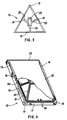
- FIG 3 is a top plan view of yet another embodiment of the semirigid support member of the present invention.
- the frame 12 is seen to be triangular in shape, as contrasted to the rectangular frames displayed in Figures 1 and 2.
- the frame 12 is designed to have a geometry similar to that of the photovoltaic module intended to be deployed thereon, that is, a flexible triangular photovoltaic module.
- each side of the frame is seen to utilize a flange portion 14 and one rib stiffener 20 extending inward toward the center of the support member.
- the rib stiffeners terminate inwardly at a rectangular structure 23 near the center of the triangular frame where additional means exists for acceptance of an electrical junction box.
- a semirigid support member in accordance with this invention is intended to make efficient use of materials as are necessary to provide structural support to a flexible photovoltaic module and to cooperate in attachment of electrical interconnects therebetween.
- FIG 4 is a partial view of a photovoltaic module assembly in accordance with the present invention.
- the support member incorporates a frame 12, a skirt 17 depending downward therefrom having thickened portions 19 in those areas wherein the frame and skirt intersect rib stiffeners 20 and wherein the support is intended to be attached to adjacent supports or to a base support means.
- Those areas of the skirt intended for attachment are thickened and have openings 18 therethrough to accept bolts, screws and the like.
- the support member shown utilizes two flanges 14 on opposing sidewalls of the rectangular frame 12.
- a flexible photovoltaic module 22 having a gasket 23 around the perimeter thereof is shown in partial cut away view.
- the module 22 is attached to the frame 12 and to rib stiffeners 20 by means of an adhesive sealant 21 such as an epoxy resin like Scotch-Weld Structural Adhesive 2216, a trademark of the 3M Corporation. Further, the flexible photovoltaic module has an electrical wiring harness (not shown) extending therefrom that is intended to be connected with external wiring in an electrical connection box, not shown, that is held in place with containment brackets 24. Such a photovoltaic module assembly is now ready for permanent deployment.
- an adhesive sealant 21 such as an epoxy resin like Scotch-Weld Structural Adhesive 2216, a trademark of the 3M Corporation.
- FIGS 5-8 are schematic views of possible means for deploying the photovoltaic module assemblies as arrays in the field. Similar features found in each of the Figures are identified by the same reference numbers. In Figures 5-8 the flexible photovoltaic modules have been omitted to provide a clear understanding of the invention.
- FIG 5 there is shown an array 30 of four semirigid support members 32.
- Each support member is similar to that depicted in Figure 1 above, each having a frame 33 incorporating a pair of oppositely disposed flanges 34, a skirt 35, and inwardly extending rib stiffeners 36 that terminate near the center of the frame in a rectangular structure 37 suitable for insertion of an electrical junction box therein.
- Each interconnected semirigid support member is secured to an adjacent support member with bolts through holes in thickened portions of the skirt 35.
- the four module array 30 is permanently deployed by attaching the two outer exposed sides of the array, 40 and 41 to a permanent base 42.
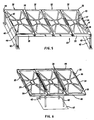
- FIG. 6 depicts an alternative embodiment of an array of semirigid photovoltaic module assemblies that can be deployed in a permanent manner.
- Each support member is similar to that depicted in Figures 1 and 5 above, having a frame 33 incorporating a pair of oppositely disposed flanges 34, a skirt 35, and inwardly extending rib stiffeners 36 that terminate near the center of the frame in a rectangular structure 37 suitable for insertion of an electrical junction box therein.
- each adjacent semirigid support number is interconnected by fastening means such as bolts extending through holes in the thickened portions of the skirt 35.
- the three module array 30, shown in Figure 6, is permanently deployed by disposing support posts 43 between adjacent photovoltaic modules. The posts 43 are in turn attached to a permanent base 42.
- the length of the post and disposition of the base are prefixed so that the array is deployed in a configuration for optimum photovoltaic responsive effectiveness.
- thickened portions of the skirt having openings therethrough may be provided along the shortened dimension of the support member and, if desired, a stabilizing bar 44 may be attached there across for additional support.
- a stabilizing bar 44 is shown at the top and bottom of the photovoltaic array 30 in Figure 6.
- FIG. 7 Still another means for deploying a photovoltaic array in accordance with the present invention is shown in Figure 7.
- the three photovoltaic module assemblies depicted in Figure 7 incorporate semirigid support members similar to the one shown in Figure 1.
- electrical interconnects between the flexible photovoltaic modules and an outside current collector can be made by utilizing a novel junction box, not shown, and a clamp 45.
- the rectangular structure 37 disposed near the center of the frame is utilized not for a conventional electrical junction box, but for a center mounted support for the photovoltaic array.
- Posts 43 extend from the rectangular structure 37 in the two outer semirigid support members and are fixedly attached to permanent bases 42.
- at least one stabilizing bar 44 may be incorporated to provide additional stability to the array.
- FIG. 8 Another means for deploying a photovoltaic array 30 in accordance with the subject invention is depicted in Figure 8.
- the three photovoltaic module support members 32 are similar to that depicted in Figure 1, having a frame 33 incorporating a pair of oppositely disposed flanges not shown, a skirt 35, and inwardly extending rib stiffeners 36 that terminate near the center of the frame in a rectangular structure not shown suitable for insertion of an electrical junction box therein.
- a rear-view of the photovoltaic array 30 is shown in Figure 8.
- the adjacent semirigid support members are not interconnected, but rather each member is attached to a common torque bar 46.
- the support members include means for accepting bolts or screws in thickened skirt areas. Bolts or screws 47 extend through the torque bar 46 and are fastened to the support members 32. This arrangement permits easy removal of any one or more photovoltaic module assembly without disturbing the remaining assemblies.
- the torque bar 46 is in turn fastened to a permanent base 42, as with support posts 43.
- the torque bar may comprise one or more bars made of aluminum, galvanized steel, wood and other materials obvious to one skilled in the art.
- the semirigid support members described hereinabove were tested in the following manner to insure their structural support.
- Two semirigid support members similar to that depicted in Figure 1 above, were made from General Electric FL 930 Resin, a tradename of the General Electric Company, and a foaming agent.
- the polycarbonate support members were bolted together through openings provided in the support member skirt.
- the support member was then subjected to a uniform pressurized loading of 2.1 kgm/m2 (50 Ibs./ft. 2 ) in a free floating load test.
- the semirigid support member was seen to have about a 5.1 cm (two-inch) deflection under these conditions. This is considered comparable to a wind loading on a photovoltaic module attached to such a support member of about 225 km/h (140 miles/hour).
- An array of modules in accordance with the subject invention were also tested for wind loading.
- Flexible photovoltaic modules were deployed onto four semirigid support members in accordance with the present invention and deployed in a configuration shown in Figure 5. Each adjacent module was connected to the next by means of two bolts. Structural steel was then used as support poles and were bolted to a fixed foundation.
- the photovoltaic array was enveloped in an enclosed space which could be pressurized alternately from above and from below the array. Air was directed against the top of the array equivalent to 145 km/h (90 miles per hour) winds up to a pressure of about 0.84 kgm/m2 (20 Ibs/ft2). The air was then allowed to exhaust while an equivalent force was directed against the back of the photovoltaic array.
- the photovoltaic array was removed from its enclosure and examined. No structural defects were found in the semirigid support members nor did the adhesive sealant that held the flexible photovoltaic modules to the support members exhibit any signs of failure.
- the semirigid support member disclosed in this specification is a light weight, economical and effective means for deployment of flexible photovoltaic modules.
Landscapes
- Engineering & Computer Science (AREA)
- Physics & Mathematics (AREA)
- Life Sciences & Earth Sciences (AREA)
- Sustainable Development (AREA)
- Sustainable Energy (AREA)
- Thermal Sciences (AREA)
- Chemical & Material Sciences (AREA)
- Combustion & Propulsion (AREA)
- Mechanical Engineering (AREA)
- General Engineering & Computer Science (AREA)
- Photovoltaic Devices (AREA)
Claims (12)
Applications Claiming Priority (2)
| Application Number | Priority Date | Filing Date | Title |
|---|---|---|---|
| US06/687,098 US4611090A (en) | 1984-12-28 | 1984-12-28 | Semirigid photovoltaic module assembly and structural support therefor |
| US687098 | 2000-10-16 |
Publications (3)
| Publication Number | Publication Date |
|---|---|
| EP0188096A2 EP0188096A2 (fr) | 1986-07-23 |
| EP0188096A3 EP0188096A3 (en) | 1987-01-14 |
| EP0188096B1 true EP0188096B1 (fr) | 1990-08-29 |
Family
ID=24759027
Family Applications (1)
| Application Number | Title | Priority Date | Filing Date |
|---|---|---|---|
| EP85309055A Expired - Lifetime EP0188096B1 (fr) | 1984-12-28 | 1985-12-12 | Assemblage semi-rigide de modules photovoltaiques et support de montage pour celui-ci |
Country Status (12)
| Country | Link |
|---|---|
| US (1) | US4611090A (fr) |
| EP (1) | EP0188096B1 (fr) |
| JP (1) | JPS61158186A (fr) |
| CN (1) | CN1003066B (fr) |
| AU (1) | AU581476B2 (fr) |
| BR (1) | BR8506547A (fr) |
| CA (1) | CA1260785A (fr) |
| DE (1) | DE3579438D1 (fr) |
| ES (1) | ES8800786A1 (fr) |
| IN (1) | IN165728B (fr) |
| MX (1) | MX159263A (fr) |
| ZA (1) | ZA859564B (fr) |
Cited By (3)
| Publication number | Priority date | Publication date | Assignee | Title |
|---|---|---|---|---|
| DE10062697A1 (de) * | 2000-12-15 | 2002-07-04 | Enbw Ag | Solarenergieanlage und Verfahren zum Aufstellen von Solarenergiemodulen |
| DE20310760U1 (de) * | 2003-07-11 | 2004-11-18 | SCHÜCO International KG | Montagesystem |
| WO2014004275A1 (fr) * | 2012-06-29 | 2014-01-03 | Sunpower Corporation | Système d'ossature pour monter des dispositifs de collecte solaire |
Families Citing this family (137)
| Publication number | Priority date | Publication date | Assignee | Title |
|---|---|---|---|---|
| JPH0625020Y2 (ja) * | 1986-09-09 | 1994-06-29 | 三洋電機株式会社 | 太陽電池装置 |
| US5164020A (en) * | 1991-05-24 | 1992-11-17 | Solarex Corporation | Solar panel |
| US5228924A (en) * | 1991-11-04 | 1993-07-20 | Mobil Solar Energy Corporation | Photovoltaic panel support assembly |
| US5647915A (en) * | 1996-06-13 | 1997-07-15 | Zukerman; Charles | Solar energy panel |
| JP3674234B2 (ja) * | 1997-04-18 | 2005-07-20 | 株式会社カネカ | 大型太陽電池モジュール |
| JPH11103086A (ja) | 1997-07-29 | 1999-04-13 | Kanegafuchi Chem Ind Co Ltd | 太陽電池モジュール |
| DE29714217U1 (de) * | 1997-08-11 | 1997-10-30 | Wismeth, Wolfgang, 90765 Fürth | Verbindungsrahmen für standarisierte Solarmodule |
| WO2003087493A1 (fr) * | 2002-04-11 | 2003-10-23 | Rwe Schott Solar Inc. | Appareil et procede d'installation de systemes de generation d'energie photovoltaique sur des batiments |
| US7574842B2 (en) * | 2002-04-11 | 2009-08-18 | Schott Solar, Inc. | Apparatus for mounting photovoltaic power generating systems on buildings |
| US7807918B2 (en) * | 2003-03-10 | 2010-10-05 | Sunpower Corporation, Systems | Modular shade system |
| CA2539419C (fr) * | 2003-08-20 | 2012-01-03 | Powerlight Corporation | Procedes et appareils d'amelioration de l'efficacite de vent photovoltaique |
| EP1751795A4 (fr) * | 2004-06-04 | 2007-08-29 | Automation Tooling Syst | Procede de construction de modules photovoltaiques rigides |
| US7081585B2 (en) * | 2004-11-02 | 2006-07-25 | Eugene Oak | Super structure for roof patio solar plant |
| US9279415B1 (en) | 2005-07-07 | 2016-03-08 | Sunlink Corporation | Solar array integration system and methods therefor |
| DE102005032716A1 (de) * | 2005-07-07 | 2007-01-11 | Pvflex Solar Produktion Gmbh | Flexibles Solarstrom-Modul mit einer im Rahmen integrierten Stromführung |
| DE102005057468A1 (de) * | 2005-11-30 | 2007-05-31 | Solarwatt Solar-Systeme Ag | Photovoltaisches rahmenloses Solarmodul in Plattenform |
| US11881814B2 (en) | 2005-12-05 | 2024-01-23 | Solaredge Technologies Ltd. | Testing of a photovoltaic panel |
| US10693415B2 (en) | 2007-12-05 | 2020-06-23 | Solaredge Technologies Ltd. | Testing of a photovoltaic panel |
| JP4866210B2 (ja) * | 2006-11-08 | 2012-02-01 | 信越化学工業株式会社 | 単結晶シリコン太陽電池の製造方法 |
| US8013472B2 (en) | 2006-12-06 | 2011-09-06 | Solaredge, Ltd. | Method for distributed power harvesting using DC power sources |
| US11309832B2 (en) | 2006-12-06 | 2022-04-19 | Solaredge Technologies Ltd. | Distributed power harvesting systems using DC power sources |
| US12316274B2 (en) | 2006-12-06 | 2025-05-27 | Solaredge Technologies Ltd. | Pairing of components in a direct current distributed power generation system |
| US8947194B2 (en) | 2009-05-26 | 2015-02-03 | Solaredge Technologies Ltd. | Theft detection and prevention in a power generation system |
| US8618692B2 (en) | 2007-12-04 | 2013-12-31 | Solaredge Technologies Ltd. | Distributed power system using direct current power sources |
| US11855231B2 (en) | 2006-12-06 | 2023-12-26 | Solaredge Technologies Ltd. | Distributed power harvesting systems using DC power sources |
| US8319483B2 (en) | 2007-08-06 | 2012-11-27 | Solaredge Technologies Ltd. | Digital average input current control in power converter |
| US11569659B2 (en) | 2006-12-06 | 2023-01-31 | Solaredge Technologies Ltd. | Distributed power harvesting systems using DC power sources |
| US11296650B2 (en) | 2006-12-06 | 2022-04-05 | Solaredge Technologies Ltd. | System and method for protection during inverter shutdown in distributed power installations |
| US9088178B2 (en) | 2006-12-06 | 2015-07-21 | Solaredge Technologies Ltd | Distributed power harvesting systems using DC power sources |
| US9112379B2 (en) | 2006-12-06 | 2015-08-18 | Solaredge Technologies Ltd. | Pairing of components in a direct current distributed power generation system |
| US8963369B2 (en) | 2007-12-04 | 2015-02-24 | Solaredge Technologies Ltd. | Distributed power harvesting systems using DC power sources |
| US11687112B2 (en) | 2006-12-06 | 2023-06-27 | Solaredge Technologies Ltd. | Distributed power harvesting systems using DC power sources |
| US8816535B2 (en) | 2007-10-10 | 2014-08-26 | Solaredge Technologies, Ltd. | System and method for protection during inverter shutdown in distributed power installations |
| US11888387B2 (en) | 2006-12-06 | 2024-01-30 | Solaredge Technologies Ltd. | Safety mechanisms, wake up and shutdown methods in distributed power installations |
| US8473250B2 (en) | 2006-12-06 | 2013-06-25 | Solaredge, Ltd. | Monitoring of distributed power harvesting systems using DC power sources |
| US9130401B2 (en) | 2006-12-06 | 2015-09-08 | Solaredge Technologies Ltd. | Distributed power harvesting systems using DC power sources |
| US8384243B2 (en) | 2007-12-04 | 2013-02-26 | Solaredge Technologies Ltd. | Distributed power harvesting systems using DC power sources |
| US11735910B2 (en) | 2006-12-06 | 2023-08-22 | Solaredge Technologies Ltd. | Distributed power system using direct current power sources |
| US8319471B2 (en) | 2006-12-06 | 2012-11-27 | Solaredge, Ltd. | Battery power delivery module |
| EP2099985A1 (fr) * | 2006-12-27 | 2009-09-16 | Dow Corning Corporation | Fixation structurelle de modules solaires à des cadres par vitrage transparent |
| US20080163921A1 (en) * | 2007-01-05 | 2008-07-10 | Solyndra, Inc., A Delaware Corporation | Three-legged solar cell support assembly |
| WO2008128163A1 (fr) * | 2007-04-13 | 2008-10-23 | Abt, Inc. | Appareil de montage d'un panneau solaire et procédé et appareil de formation de l'appareil de montage |
| US9022020B2 (en) | 2007-08-27 | 2015-05-05 | Areva Solar, Inc. | Linear Fresnel solar arrays and drives therefor |
| US20090056703A1 (en) * | 2007-08-27 | 2009-03-05 | Ausra, Inc. | Linear fresnel solar arrays and components therefor |
| EP3496258B1 (fr) | 2007-12-05 | 2025-02-05 | Solaredge Technologies Ltd. | Mécanismes de sécurité dans des installations de puissance réparties |
| US11264947B2 (en) | 2007-12-05 | 2022-03-01 | Solaredge Technologies Ltd. | Testing of a photovoltaic panel |
| US8049523B2 (en) | 2007-12-05 | 2011-11-01 | Solaredge Technologies Ltd. | Current sensing on a MOSFET |
| US8748727B2 (en) | 2008-01-18 | 2014-06-10 | Tenksolar, Inc. | Flat-plate photovoltaic module |
| US8933320B2 (en) | 2008-01-18 | 2015-01-13 | Tenksolar, Inc. | Redundant electrical architecture for photovoltaic modules |
| US8212139B2 (en) * | 2008-01-18 | 2012-07-03 | Tenksolar, Inc. | Thin-film photovoltaic module |
| EP4145691A1 (fr) | 2008-03-24 | 2023-03-08 | Solaredge Technologies Ltd. | Convertisseur à découpage avec circuit auxiliaire de commutation par courant nul |
| US20090255530A1 (en) * | 2008-04-14 | 2009-10-15 | Abt, Inc. | Apparatus for mounting a solar panel and method and apparatus for forming the mounting apparatus |
| EP3121922B1 (fr) | 2008-05-05 | 2020-03-04 | Solaredge Technologies Ltd. | Combineur de puissance en courant continu |
| DE102008027857A1 (de) * | 2008-06-11 | 2009-03-05 | Leichtmetallbau Schletter Gmbh | Montagesystem für PV-Module |
| WO2010003102A1 (fr) | 2008-07-02 | 2010-01-07 | Laurence Mackler | Ensemble afficheur de production d’énergie solaire et procédé pour le fournir |
| US8413391B2 (en) | 2008-10-13 | 2013-04-09 | Sunlink Corporation | Solar array mounting system with universal clamp |
| WO2010068706A2 (fr) * | 2008-12-10 | 2010-06-17 | Armageddon Energy, Inc. | Configurations de panneaux solaires |
| TW201036183A (en) * | 2008-12-16 | 2010-10-01 | Solopower Inc | Thin film photovoltaic module manufacturing methods and structures |
| DE102008055561A1 (de) * | 2008-12-19 | 2010-07-01 | Schott Solar Ag | Verfahren zum Herstellen eines Halbleiterbauelementrahmens sowie Halbleiterbauelementrahmen |
| US8294022B2 (en) * | 2009-04-01 | 2012-10-23 | Sunpower Corporation | Photovoltaic array with minimally penetrating rooftop support system |
| ES2326586B1 (es) * | 2009-04-17 | 2010-05-25 | Sener Ingenieria Y Sistemas, S.A. | Faceta para heliostato. |
| US8492645B1 (en) * | 2009-04-22 | 2013-07-23 | Michael Strahm | Transportable solar power system |
| IN2012DN00387A (fr) | 2009-06-15 | 2015-08-21 | Tenksolar Inc | |
| USD611405S1 (en) * | 2009-07-02 | 2010-03-09 | Solaire Generation LLC | Solar power generation assembly |
| USD611404S1 (en) * | 2009-07-02 | 2010-03-09 | Solaire Generation LLC | Solar power generation assembly |
| DE202009018257U1 (de) * | 2009-07-29 | 2011-05-19 | Anicca Ag, 10707 | Anordnung zur Verringerung der Durchbiegung der durch einen Rahmen eingefassten Laminate von Photovoltaik-Modulen |
| US12418177B2 (en) | 2009-10-24 | 2025-09-16 | Solaredge Technologies Ltd. | Distributed power system using direct current power sources |
| EP2504859A4 (fr) * | 2009-11-25 | 2015-05-27 | Banyan Energy Inc | Réalisation de module solaire |
| USD631824S1 (en) * | 2009-12-09 | 2011-02-01 | Sanyo Electric Co., Ltd. | Shed with solar-battery |
| DE102009059232A1 (de) | 2009-12-18 | 2011-06-22 | SCHOTT Solar AG, 55122 | Verfahren zum Herstellen eines Rahmens sowie Solarzellenmodulrahmen |
| US9773933B2 (en) | 2010-02-23 | 2017-09-26 | Tenksolar, Inc. | Space and energy efficient photovoltaic array |
| US9299861B2 (en) | 2010-06-15 | 2016-03-29 | Tenksolar, Inc. | Cell-to-grid redundandt photovoltaic system |
| KR101425136B1 (ko) | 2010-08-10 | 2014-08-04 | 텐케이솔라 인코포레이티드 | 고효율 태양전지판 |
| US10673229B2 (en) | 2010-11-09 | 2020-06-02 | Solaredge Technologies Ltd. | Arc detection and prevention in a power generation system |
| US10230310B2 (en) | 2016-04-05 | 2019-03-12 | Solaredge Technologies Ltd | Safety switch for photovoltaic systems |
| GB2485527B (en) | 2010-11-09 | 2012-12-19 | Solaredge Technologies Ltd | Arc detection and prevention in a power generation system |
| US10673222B2 (en) | 2010-11-09 | 2020-06-02 | Solaredge Technologies Ltd. | Arc detection and prevention in a power generation system |
| GB2486408A (en) | 2010-12-09 | 2012-06-20 | Solaredge Technologies Ltd | Disconnection of a string carrying direct current |
| JP5687486B2 (ja) * | 2010-12-28 | 2015-03-18 | 大成建設株式会社 | シート状太陽光発電モジュール取付け工法 |
| GB2483317B (en) | 2011-01-12 | 2012-08-22 | Solaredge Technologies Ltd | Serially connected inverters |
| US20150377521A1 (en) * | 2011-03-01 | 2015-12-31 | Jonathan Port | Strap mount for solar panels |
| USD657735S1 (en) * | 2011-05-20 | 2012-04-17 | Solaire Generations, Inc. | Solar power generation assembly |
| USD657738S1 (en) * | 2011-05-20 | 2012-04-17 | Solaire Generation, Inc. | Solar power generation assembly |
| USD657737S1 (en) * | 2011-05-20 | 2012-04-17 | Solaire Generations, Inc. | Solar power generation assembly |
| USD657736S1 (en) * | 2011-05-20 | 2012-04-17 | Solaire Generation, Inc. | Solar power generation assembly |
| US8336277B1 (en) | 2011-07-07 | 2012-12-25 | Solon Corporation | Integrated photovoltaic rooftop modules |
| US8570005B2 (en) | 2011-09-12 | 2013-10-29 | Solaredge Technologies Ltd. | Direct current link circuit |
| DE102011053583A1 (de) | 2011-09-14 | 2013-03-14 | Reis Group Holding Gmbh & Co. Kg | Plattenförmiges Modul sowie Verfahren zum Herstellen eines Rahmens für ein solches |
| US9038329B2 (en) | 2011-10-11 | 2015-05-26 | Sunlink Corporation | Structure following roof mounted photovoltaic system |
| US20130112247A1 (en) * | 2011-11-09 | 2013-05-09 | Taiwan Semiconductor Manufacturing Co. Solar, Ltd. | Frame for solar panels |
| GB2498365A (en) | 2012-01-11 | 2013-07-17 | Solaredge Technologies Ltd | Photovoltaic module |
| US9853565B2 (en) | 2012-01-30 | 2017-12-26 | Solaredge Technologies Ltd. | Maximized power in a photovoltaic distributed power system |
| GB2498790A (en) | 2012-01-30 | 2013-07-31 | Solaredge Technologies Ltd | Maximising power in a photovoltaic distributed power system |
| GB2498791A (en) | 2012-01-30 | 2013-07-31 | Solaredge Technologies Ltd | Photovoltaic panel circuitry |
| GB2499991A (en) | 2012-03-05 | 2013-09-11 | Solaredge Technologies Ltd | DC link circuit for photovoltaic array |
| WO2013135757A1 (fr) | 2012-03-13 | 2013-09-19 | Termopower, S.L | Facette d'héliostat et procédure de fabrication de celle-ci |
| EP2639525A1 (fr) | 2012-03-13 | 2013-09-18 | Termopower S.L. | Facette d'héliostat et son procédé de fabrication |
| JP2012160764A (ja) * | 2012-05-28 | 2012-08-23 | Sharp Corp | 太陽電池アレイ及びその設置構造 |
| US10115841B2 (en) * | 2012-06-04 | 2018-10-30 | Solaredge Technologies Ltd. | Integrated photovoltaic panel circuitry |
| WO2013184164A1 (fr) * | 2012-06-08 | 2013-12-12 | Solopower , Inc. | Ensemble module solaire intégré de toit |
| US20140069500A1 (en) * | 2012-09-10 | 2014-03-13 | Primestar Solar, Inc. | Support structure for photovoltaic module mounting and methods of its use |
| US9263985B2 (en) | 2012-11-13 | 2016-02-16 | Pi Solar Technology Gmbh | Rooftop photovoltaic modules |
| US9742347B2 (en) | 2013-02-11 | 2017-08-22 | Jonathan Port | Modular strap mount for solar panels |
| US9548619B2 (en) | 2013-03-14 | 2017-01-17 | Solaredge Technologies Ltd. | Method and apparatus for storing and depleting energy |
| EP2779251B1 (fr) | 2013-03-15 | 2019-02-27 | Solaredge Technologies Ltd. | Mécanisme de dérivation |
| EP2804224A1 (fr) | 2013-05-13 | 2014-11-19 | Fraunhofer Gesellschaft zur Förderung der angewandten Forschung e.V. | Procédé de fabrication d'un module photovoltaïque |
| EP3005421B1 (fr) * | 2013-05-31 | 2017-08-09 | Dow Global Technologies LLC | Structure de support pour un module solaire |
| USD754064S1 (en) | 2013-08-05 | 2016-04-19 | Sunpower Corporation | Solar power generation assembly |
| USD751976S1 (en) | 2013-08-05 | 2016-03-22 | Sunpower Corporation | Solar power generation assembly |
| USD819137S1 (en) | 2013-08-05 | 2018-05-29 | Sunpower Corporation | Column cover |
| USD774450S1 (en) | 2013-08-05 | 2016-12-20 | Sunpower Corporation | Photovoltaic sundial assembly |
| US8991117B1 (en) * | 2014-05-05 | 2015-03-31 | Solur Terra, Inc. | Solar and rainwater tower |
| CN104183662A (zh) * | 2014-07-23 | 2014-12-03 | 湖南红太阳新能源科技有限公司 | 一种柔性太阳能光伏组件的衬底 |
| CN204987526U (zh) * | 2015-06-15 | 2016-01-20 | 北京首航艾启威节能技术股份有限公司 | 一种定日镜冲压金属支架 |
| FR3040716B1 (fr) * | 2015-09-07 | 2017-11-17 | Helios Generation | Structure de toiture comprenant un module photovoltaique semi-rigide, procede de realisation de celle-ci, et gabarit de pose pour ledit procede |
| CN105515503B (zh) * | 2015-11-26 | 2018-01-16 | 中国电子科技集团公司第十八研究所 | 一种绷弦式半刚性板的太阳电池模块固定结构和固定方法 |
| CN107153212B (zh) | 2016-03-03 | 2023-07-28 | 太阳能安吉科技有限公司 | 用于映射发电设施的方法 |
| US11081608B2 (en) | 2016-03-03 | 2021-08-03 | Solaredge Technologies Ltd. | Apparatus and method for determining an order of power devices in power generation systems |
| US10599113B2 (en) | 2016-03-03 | 2020-03-24 | Solaredge Technologies Ltd. | Apparatus and method for determining an order of power devices in power generation systems |
| US12057807B2 (en) | 2016-04-05 | 2024-08-06 | Solaredge Technologies Ltd. | Chain of power devices |
| US11018623B2 (en) | 2016-04-05 | 2021-05-25 | Solaredge Technologies Ltd. | Safety switch for photovoltaic systems |
| US11177663B2 (en) | 2016-04-05 | 2021-11-16 | Solaredge Technologies Ltd. | Chain of power devices |
| US11502640B2 (en) * | 2016-06-29 | 2022-11-15 | Sunpower Corporation | Photovoltaic panel having an adhered support frame |
| US11139776B2 (en) * | 2016-07-01 | 2021-10-05 | Sunpower Corporation | Photovoltaic panel having a distributed support frame |
| CN106125254B (zh) * | 2016-08-24 | 2019-05-14 | 东方电气集团东方锅炉股份有限公司 | 一种微弧面反射镜冲压背板 |
| US9628019B1 (en) * | 2016-09-09 | 2017-04-18 | Polar Racking Inc. | Photovoltaic panel racking system |
| US20190154305A1 (en) * | 2017-11-14 | 2019-05-23 | Quest Renewables, Llc | Apparatuses, systems, and methods for a self-balanced photovoltaic system |
| US10490682B2 (en) | 2018-03-14 | 2019-11-26 | National Mechanical Group Corp. | Frame-less encapsulated photo-voltaic solar panel supporting solar cell modules encapsulated within multiple layers of optically-transparent epoxy-resin materials |
| WO2019191710A1 (fr) | 2018-03-30 | 2019-10-03 | Sunpower Corporation | Module photovoltaïque doté d'un ensemble rail transversal |
| EP3776845A4 (fr) * | 2018-03-30 | 2021-03-31 | Sunpower Corporation | Module photovoltaïque doté d'un ensemble rail transversal |
| EP3562032A1 (fr) | 2018-04-25 | 2019-10-30 | Total SA | Module photovoltaïque et procédé de fabrication d'un module photovoltaïque |
| US20240235470A1 (en) | 2023-01-09 | 2024-07-11 | Sarcos Corp. | Auto-Engaging Electrical Connections for Solar Panels |
| US12244262B2 (en) * | 2023-01-09 | 2025-03-04 | Sarcos Corp. | Capture and support mount for retaining installed solar panels |
| US20240228195A1 (en) * | 2023-01-09 | 2024-07-11 | Sarcos Corp. | Solar Panel Dispensing System for Facilitating Installation of Solar Panels |
| US12466066B2 (en) | 2023-05-04 | 2025-11-11 | Sarcos Corp. | Solar panel dispensing device with vertical solar panel hopper loading and dispensing |
| US12542513B2 (en) | 2024-01-08 | 2026-02-03 | Sarcos Corp. | Torque tube clamps for automated solar panel installation |
| US12570001B2 (en) | 2024-01-08 | 2026-03-10 | Sarcos Corp. | Support clamp installation vehicles as part of a solar panel installation system for a solar tracking system |
Family Cites Families (10)
| Publication number | Priority date | Publication date | Assignee | Title |
|---|---|---|---|---|
| US3181869A (en) * | 1962-04-04 | 1965-05-04 | Child Guidance Toys Inc | Puzzle board toy assembly |
| US4015653A (en) * | 1976-04-08 | 1977-04-05 | General Dynamics Corporation | Panel deployment system |
| FR2350695A1 (fr) * | 1976-05-03 | 1977-12-02 | Aerospatiale | Generateur solaire d'energie electrique |
| US4132570A (en) * | 1977-08-24 | 1979-01-02 | Exxon Research & Engineering Co. | Structural support for solar cell array |
| US4172739A (en) * | 1977-12-27 | 1979-10-30 | Solar Homes, Inc. | Sun tracker with dual axis support for diurnal movement and seasonal adjustment |
| US4217374A (en) * | 1978-03-08 | 1980-08-12 | Energy Conversion Devices, Inc. | Amorphous semiconductors equivalent to crystalline semiconductors |
| US4239555A (en) * | 1979-07-30 | 1980-12-16 | Mobil Tyco Solar Energy Corporation | Encapsulated solar cell array |
| US4312325A (en) * | 1980-03-17 | 1982-01-26 | Red Bud Industries, Inc. | Solar heating system |
| US4392009A (en) * | 1981-10-16 | 1983-07-05 | Exxon Research And Engineering Co. | Solar power module |
| DE3231798A1 (de) * | 1982-08-26 | 1984-03-01 | Licentia Patent-Verwaltungs-Gmbh, 6000 Frankfurt | Verfahren zur herstellung eines solargenerators fuer solartechnische grossanlagen |
-
1984
- 1984-12-28 US US06/687,098 patent/US4611090A/en not_active Expired - Fee Related
-
1985
- 1985-11-21 CA CA000495897A patent/CA1260785A/fr not_active Expired
- 1985-11-29 IN IN1010/DEL/IKA patent/IN165728B/en unknown
- 1985-12-02 AU AU50550/85A patent/AU581476B2/en not_active Ceased
- 1985-12-12 DE DE8585309055T patent/DE3579438D1/de not_active Expired - Fee Related
- 1985-12-12 EP EP85309055A patent/EP0188096B1/fr not_active Expired - Lifetime
- 1985-12-13 ZA ZA859564A patent/ZA859564B/xx unknown
- 1985-12-20 MX MX1126A patent/MX159263A/es unknown
- 1985-12-25 CN CN85109335A patent/CN1003066B/zh not_active Expired
- 1985-12-25 JP JP60299757A patent/JPS61158186A/ja active Pending
- 1985-12-27 ES ES550462A patent/ES8800786A1/es not_active Expired
- 1985-12-27 BR BR8506547A patent/BR8506547A/pt unknown
Cited By (5)
| Publication number | Priority date | Publication date | Assignee | Title |
|---|---|---|---|---|
| DE10062697A1 (de) * | 2000-12-15 | 2002-07-04 | Enbw Ag | Solarenergieanlage und Verfahren zum Aufstellen von Solarenergiemodulen |
| DE10062697B4 (de) * | 2000-12-15 | 2006-06-08 | Rbs Genius Gmbh | Verfahren zum Aufstellen von Solarenergiemodulen auf nicht stabilisiertem Untergrund und Solarenergieanlage |
| DE20310760U1 (de) * | 2003-07-11 | 2004-11-18 | SCHÜCO International KG | Montagesystem |
| WO2014004275A1 (fr) * | 2012-06-29 | 2014-01-03 | Sunpower Corporation | Système d'ossature pour monter des dispositifs de collecte solaire |
| US9316417B2 (en) | 2012-06-29 | 2016-04-19 | Sunpower Corporation | Framing system for mounting solar collecting devices |
Also Published As
| Publication number | Publication date |
|---|---|
| ES8800786A1 (es) | 1987-11-16 |
| ES550462A0 (es) | 1987-11-16 |
| US4611090A (en) | 1986-09-09 |
| AU581476B2 (en) | 1989-02-23 |
| CA1260785A (fr) | 1989-09-26 |
| AU5055085A (en) | 1986-07-03 |
| JPS61158186A (ja) | 1986-07-17 |
| CN85109335A (zh) | 1986-07-09 |
| ZA859564B (en) | 1986-08-27 |
| BR8506547A (pt) | 1986-09-09 |
| DE3579438D1 (de) | 1990-10-04 |
| EP0188096A2 (fr) | 1986-07-23 |
| IN165728B (fr) | 1989-12-30 |
| CN1003066B (zh) | 1989-01-11 |
| EP0188096A3 (en) | 1987-01-14 |
| MX159263A (es) | 1989-05-11 |
Similar Documents
| Publication | Publication Date | Title |
|---|---|---|
| EP0188096B1 (fr) | Assemblage semi-rigide de modules photovoltaiques et support de montage pour celui-ci | |
| KR101126059B1 (ko) | 태양광 발전용 모듈 및 이것을 이용한 태양광 발전 시스템 | |
| US20150155819A1 (en) | Hole-thru-laminate mounting supports for photovoltaic modules | |
| US20230231059A1 (en) | Solar module having a plurality of strings configured from a five strip cell | |
| EP0017334A1 (fr) | Module de panneaux solaires | |
| US20090293941A1 (en) | Photovoltaic power farm structure and installation | |
| US10381498B2 (en) | Flexible laminates for solar modules | |
| WO2006031798A2 (fr) | Modules de miroirs photovoltaiques solaires | |
| US20250112585A1 (en) | Hemispherical solar panel for enhanced light absorption | |
| EP4170899B1 (fr) | Structure de réseau photovoltaïque à faible perte de ligne | |
| US20200295208A1 (en) | Apparatus and method for solar panel | |
| JP3633944B2 (ja) | 太陽電池モジュールおよびそれを用いた太陽電池アレイ | |
| JP2007180314A (ja) | 太陽電池モジュール | |
| US20210226575A1 (en) | Method using Embossing Tamper and Method for Earth Mount Utility Scale Photovoltaic Array | |
| JPH03199566A (ja) | 屋根設置型太陽電池装置の設置方法 | |
| CN223194629U (zh) | 一种光伏组件 | |
| US20250338635A1 (en) | Mosaic coverglass for space power modules | |
| CN101006589A (zh) | 太阳光发电用模块及使用其的太阳光发电系统 | |
| KR20130122267A (ko) | 태양광 발전장치 | |
| JP2007180065A (ja) | 太陽電池アレイ | |
| JP2022117617A (ja) | 太陽光発電装置 | |
| WO2025126467A1 (fr) | Structure de cellule solaire et procédé d'installation de cellule solaire | |
| CN120345176A (zh) | 单元块型光伏模块 | |
| JP2004193375A (ja) | 太陽電池アレイ | |
| Bollani et al. | Thin GaAs/Ge solar cell development |
Legal Events
| Date | Code | Title | Description |
|---|---|---|---|
| PUAI | Public reference made under article 153(3) epc to a published international application that has entered the european phase |
Free format text: ORIGINAL CODE: 0009012 |
|
| AK | Designated contracting states |
Kind code of ref document: A2 Designated state(s): DE FR GB IT NL |
|
| PUAL | Search report despatched |
Free format text: ORIGINAL CODE: 0009013 |
|
| AK | Designated contracting states |
Kind code of ref document: A3 Designated state(s): DE FR GB IT NL |
|
| 17P | Request for examination filed |
Effective date: 19870611 |
|
| 17Q | First examination report despatched |
Effective date: 19891010 |
|
| GRAA | (expected) grant |
Free format text: ORIGINAL CODE: 0009210 |
|
| AK | Designated contracting states |
Kind code of ref document: B1 Designated state(s): DE FR GB IT NL |
|
| ITF | It: translation for a ep patent filed | ||
| REF | Corresponds to: |
Ref document number: 3579438 Country of ref document: DE Date of ref document: 19901004 |
|
| ET | Fr: translation filed | ||
| PGFP | Annual fee paid to national office [announced via postgrant information from national office to epo] |
Ref country code: GB Payment date: 19901119 Year of fee payment: 6 |
|
| PGFP | Annual fee paid to national office [announced via postgrant information from national office to epo] |
Ref country code: FR Payment date: 19901218 Year of fee payment: 6 |
|
| PGFP | Annual fee paid to national office [announced via postgrant information from national office to epo] |
Ref country code: DE Payment date: 19901221 Year of fee payment: 6 |
|
| ITTA | It: last paid annual fee | ||
| PGFP | Annual fee paid to national office [announced via postgrant information from national office to epo] |
Ref country code: NL Payment date: 19901231 Year of fee payment: 6 |
|
| PLBE | No opposition filed within time limit |
Free format text: ORIGINAL CODE: 0009261 |
|
| STAA | Information on the status of an ep patent application or granted ep patent |
Free format text: STATUS: NO OPPOSITION FILED WITHIN TIME LIMIT |
|
| 26N | No opposition filed | ||
| PG25 | Lapsed in a contracting state [announced via postgrant information from national office to epo] |
Ref country code: GB Effective date: 19911212 |
|
| PG25 | Lapsed in a contracting state [announced via postgrant information from national office to epo] |
Ref country code: NL Effective date: 19920701 |
|
| GBPC | Gb: european patent ceased through non-payment of renewal fee | ||
| NLV4 | Nl: lapsed or anulled due to non-payment of the annual fee | ||
| PG25 | Lapsed in a contracting state [announced via postgrant information from national office to epo] |
Ref country code: FR Effective date: 19920831 |
|
| PG25 | Lapsed in a contracting state [announced via postgrant information from national office to epo] |
Ref country code: DE Effective date: 19920901 |
|
| REG | Reference to a national code |
Ref country code: FR Ref legal event code: ST |