EP0188265A2 - Verfahren zur Flüssigkeitsspende - Google Patents
Verfahren zur Flüssigkeitsspende Download PDFInfo
- Publication number
- EP0188265A2 EP0188265A2 EP86100381A EP86100381A EP0188265A2 EP 0188265 A2 EP0188265 A2 EP 0188265A2 EP 86100381 A EP86100381 A EP 86100381A EP 86100381 A EP86100381 A EP 86100381A EP 0188265 A2 EP0188265 A2 EP 0188265A2
- Authority
- EP
- European Patent Office
- Prior art keywords
- liquid
- conduit
- inner conduit
- sample
- set forth
- Prior art date
- Legal status (The legal status is an assumption and is not a legal conclusion. Google has not performed a legal analysis and makes no representation as to the accuracy of the status listed.)
- Granted
Links
- 239000007788 liquid Substances 0.000 title claims abstract description 114
- 238000000034 method Methods 0.000 title claims description 16
- 239000003085 diluting agent Substances 0.000 claims abstract description 31
- 239000000523 sample Substances 0.000 claims description 145
- 238000011010 flushing procedure Methods 0.000 claims description 11
- 238000007654 immersion Methods 0.000 claims description 2
- 230000003213 activating effect Effects 0.000 claims 1
- 238000007598 dipping method Methods 0.000 claims 1
- 239000012530 fluid Substances 0.000 abstract description 17
- 238000007865 diluting Methods 0.000 abstract description 3
- XLYOFNOQVPJJNP-UHFFFAOYSA-N water Substances O XLYOFNOQVPJJNP-UHFFFAOYSA-N 0.000 description 15
- 238000004458 analytical method Methods 0.000 description 7
- 230000008901 benefit Effects 0.000 description 7
- 238000011109 contamination Methods 0.000 description 7
- 238000005070 sampling Methods 0.000 description 6
- 230000000694 effects Effects 0.000 description 5
- 239000002699 waste material Substances 0.000 description 5
- 238000006243 chemical reaction Methods 0.000 description 4
- HEMHJVSKTPXQMS-UHFFFAOYSA-M Sodium hydroxide Chemical compound [OH-].[Na+] HEMHJVSKTPXQMS-UHFFFAOYSA-M 0.000 description 3
- 238000013459 approach Methods 0.000 description 3
- 238000002360 preparation method Methods 0.000 description 3
- 229910001220 stainless steel Inorganic materials 0.000 description 3
- 239000010935 stainless steel Substances 0.000 description 3
- 238000005406 washing Methods 0.000 description 3
- 238000010586 diagram Methods 0.000 description 2
- 238000006073 displacement reaction Methods 0.000 description 2
- 239000000463 material Substances 0.000 description 2
- 229910052751 metal Inorganic materials 0.000 description 2
- 239000002184 metal Substances 0.000 description 2
- 239000000203 mixture Substances 0.000 description 2
- 230000008569 process Effects 0.000 description 2
- 239000000243 solution Substances 0.000 description 2
- 238000003466 welding Methods 0.000 description 2
- FAPWRFPIFSIZLT-UHFFFAOYSA-M Sodium chloride Chemical compound [Na+].[Cl-] FAPWRFPIFSIZLT-UHFFFAOYSA-M 0.000 description 1
- 239000004809 Teflon Substances 0.000 description 1
- 229920006362 Teflon® Polymers 0.000 description 1
- 238000002835 absorbance Methods 0.000 description 1
- 238000011481 absorbance measurement Methods 0.000 description 1
- NIXOWILDQLNWCW-UHFFFAOYSA-N acrylic acid group Chemical group C(C=C)(=O)O NIXOWILDQLNWCW-UHFFFAOYSA-N 0.000 description 1
- 230000009471 action Effects 0.000 description 1
- 230000015572 biosynthetic process Effects 0.000 description 1
- 239000007853 buffer solution Substances 0.000 description 1
- 239000003153 chemical reaction reagent Substances 0.000 description 1
- 238000004140 cleaning Methods 0.000 description 1
- 238000004891 communication Methods 0.000 description 1
- 238000010276 construction Methods 0.000 description 1
- 230000008878 coupling Effects 0.000 description 1
- 238000010168 coupling process Methods 0.000 description 1
- 238000005859 coupling reaction Methods 0.000 description 1
- 238000002788 crimping Methods 0.000 description 1
- 238000012864 cross contamination Methods 0.000 description 1
- 238000013461 design Methods 0.000 description 1
- 239000012895 dilution Substances 0.000 description 1
- 238000010790 dilution Methods 0.000 description 1
- 210000004907 gland Anatomy 0.000 description 1
- -1 i.e. Substances 0.000 description 1
- 230000007246 mechanism Effects 0.000 description 1
- 230000005499 meniscus Effects 0.000 description 1
- 230000009972 noncorrosive effect Effects 0.000 description 1
- 238000012856 packing Methods 0.000 description 1
- 230000002093 peripheral effect Effects 0.000 description 1
- 238000010944 pre-mature reactiony Methods 0.000 description 1
- 239000011541 reaction mixture Substances 0.000 description 1
- 229920006395 saturated elastomer Polymers 0.000 description 1
- 229920002545 silicone oil Polymers 0.000 description 1
- 238000002791 soaking Methods 0.000 description 1
- 239000011780 sodium chloride Substances 0.000 description 1
- 238000002798 spectrophotometry method Methods 0.000 description 1
- 238000012360 testing method Methods 0.000 description 1
- 238000009736 wetting Methods 0.000 description 1
- 230000003245 working effect Effects 0.000 description 1
Images



Classifications
-
- G—PHYSICS
- G01—MEASURING; TESTING
- G01N—INVESTIGATING OR ANALYSING MATERIALS BY DETERMINING THEIR CHEMICAL OR PHYSICAL PROPERTIES
- G01N35/00—Automatic analysis not limited to methods or materials provided for in any single one of groups G01N1/00 - G01N33/00; Handling materials therefor
- G01N35/10—Devices for transferring samples or any liquids to, in, or from, the analysis apparatus, e.g. suction devices, injection devices
-
- G—PHYSICS
- G01—MEASURING; TESTING
- G01N—INVESTIGATING OR ANALYSING MATERIALS BY DETERMINING THEIR CHEMICAL OR PHYSICAL PROPERTIES
- G01N1/00—Sampling; Preparing specimens for investigation
- G01N1/28—Preparing specimens for investigation including physical details of (bio-)chemical methods covered elsewhere, e.g. G01N33/50, C12Q
- G01N1/38—Diluting, dispersing or mixing samples
Definitions
- This invention relates to a method of and apparatus for aspirating and dispensing small volumes of liquid.
- the major problem associated with metering small quantities of liquid is the inability to successfully deliver such quantities in a reproducible manner.
- the volume of a liquid drop which may be on the order of 50 microliters, is 10 to 100 times the volume of sample required for some analyses. Consequently the process of liquid dispensing must be precisely controlled to insure adequate dispensing precision, i.e., the ability to dispense exactly the same volume of a sample each time.
- the immiscible fluid is dispensed, along with an air segment, between aspirations of successive samples, each dispensed air and sample segment being encapsulated by such immiscible fluid while passing through such system.
- the disadvantage of this system is the contamination of the sample mixture with the "immiscible" fluid and the inability of the system to precisely control the liquid drop formation and dispensed volume.
- Chen utilizes an inner needle coaxially disposed in an outer conduit. The sample is dispensed through the inner needle and then a diluent is dispensed through both the inner needle and outer conduit. This accomplishes rapid and convenient liquid dispensing but cannot insure precise, reproducible sample delivery or dilutions since the sample aspiration is not controlled as to wetting of the outer surface of the inner needle.
- Toshiba use a syringe pipette on their TBA580 Clinical Analyzer.
- the syringe tip is a metal needle.
- the wash is water which is squirted at the sample needle by a separate flush needle - (non-contacting, non-coaxial). This system suffers from the large amount of flush water required and the imprecision due to the water that remains on the sample and flush needles after dispensing.
- small samples of a first liquid are aspirated and dispensed using a probe having inner and outer coaxially disposed conduits defining a coaxial region by: aspirating the first liquid into the inner conduit and the annular space between the conduits, flushing the annular space with a second liquid miscible with the first liquid to remove the first liquid from the annular space and hence the exterior of the inner conduit and establish a controlled interface between the conduits, dispensing a predetermined quantity of the first liquid from the inner conduit into the second liquid in the coaxial region, and flushing the annular space with a predetermined quantity of the second liquid thereby dispensing the first liquid.
- the method may include contacting the tip of the outer probe with a surface to remove excess liquid prior to dispensing and flushing.
- the inner conduit can alone be extended axially for immersion in the first liquid prior to aspiration, and withdrawn into the outer conduit prior to the initial flushing.
- This method has many advantages. For one, it provides for better volumetric repeatability since the sample is directly dispensed into a miscible carrier fluid. This eliminates the uncertainty associated with surface tension effects and dtbp adhesion to the needle tip. Also, since the outside surface of the inner needle is flushed with an inocuous second liquid prior to sample aspiration, sample-to-sample contamination is reduced.
- Other configurations may take the form of an outer conduit of reduced diameter at the inlet end, an inner conduit of reduced diameter at the inlet end, or reduced diameter at the inlet ends of both the inner and outer conduits.
- the inner conduit is positionable along the axis of the outer conduit and is slideably centered relative to that axis by protuberances in the inner wall of the outer conduit.
- the coaxial positionable inner movable conduit affords the many advantages set forth above. Samples are accurately and reproduceably dispensed without cross contaminating the reaction mixture. There is also less sample waste due to the smaller surface area wetted by the sample. Also, the external surface of the outer conduit is never in contact with the sample, thereby reducing contamination.
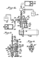
- Fig. 1 a block diagram of a coaxial pipetting sampling system constructed in accordance with this invention.
- the apparatus includes a command generator 20, which is used to create the commands which are transmitted to a sample turntable 34 and to a probe sequence controller 22.
- the probe sequence controller 22 in turn controls the operation of both a sample pump 24 and a diluent pump 26 and the probe assembly 32.
- the probe sequence controller 22 also regulates the position of selector valves 36 and 38 which connect the diluent pump 26 to either a probe assembly 32 or a first reservoir 30 and the sample pump 24 to either the probe assembly 32 or a second reservoir 28.
- the probe assembly operates to aspirate samples from a sample turntable 3 4 as will be described.
- the probe assembly 32 has a probe housing 49 - (Fig. 4) which defines a manifold 51.
- An outer conduit 60 is secured to the manifold as by welding and an inner conduit 61 is fixed positioned by the housing 49 and extends downwardly through the manifold 51 and is coaxially and fixedly located within the outer conduit 60 extending to a point just short of the open end of the outer conduit 60.
- the housing 49 is mounted to be vertically positionable by way of a helical lead screw 54 driven by stepper motor 66.
- the stepper motor in turn is controlled by the sequence controller 22.
- a housing guide rod 64 is vertically mounted to a base 67 to facilitate the vertical displacement of the probe housing 49.
- the inner conduit 61 is connected through a sample tubing 40 to the selector valve 36 which links the sample pump 2 4 either to the liquid reservoir 28 or directly to the inner conduit 61.
- the manifold 5 1 and hence the outer conduit 60 is connected via a coupling 58 which is secured to the probe housing 49 to a selector valve 38 through tubing 56.
- the diluent pump 26 is connected through tubing 56 and the selector valve 38 to either the manifold 51 or to the liquid reservoir 30.
- the probe assembly is a two-piece construction comprising the probe housing 49 and a support bracket 57, typically fabricated from a non-corrosive metal such as stainless steel and held together via cap screws 65. Housing guide rods 64 communicate with the probe support bracket 57 via a slideable contact means allowing for proper vertical displacement.
- the lead screw 54 engages a bracket arm 55 as best seen in Figure 4 to position the probe assembly 32 vertically.
- the coaxial probe assembly can either be fixed in place as a bench top instrument or can be integrated into a larger apparatus.
- sample turntable 34 such as the FIA-07, made by Bifok of Sweden can be used im conjunction with the coaxial sampling system for sample analysis.
- the sample turntable 34 typically houses a plurality of sample carrying containers 74 which are placed about the circumference of a rotatable carousel.
- the carousel can either be manually rotated into position or programmably controlled. Therefore depending upon application the samples can be positioned such that the probe assembly 32 can easily access the samples for analysis preparation and the like.
- Illustrated in Figure 4 is the sample container 74 which is positioned for sample preparation by the sample turntable 34.
- the command generator 20 may be a Hewlett-Packard 85 computer and the sequence controller 22 may be an Intel SDK-85 microcomputer.
- the pumps 24 and 26 may be ones manufactured by Hamilton, Inc., of Reno, Nevada having a capacity of 1 00 and 2500 microliters respectively.
- the arrangement using the valves 36 and 38 to connect the respective pumps 24 and 26 to either the respective reservoirs 28, 30 or the inner and outer conduits 60 and 6 1 allows the sample liquid to be flushed from the tips of the conduits 60, 61 without having to draw flush water through the contaminated conduit.
- residual oil and dirt is removed from the tips of both conduits by soaking them in a 10 normal sodium hydroxide (50% saturated) solution for 20 minutes followed by rinsing with water.
- the inner conduit 61 may be constructed using a 21 ga. thin wall stainless steel needle tubing (part number HTX-21 TW SS 403 from Small Parts, Inc., Miami, Florida 33138).
- the tip may be ground flat and approximately normal to the long axis.
- the outer conduit 60 a 1-inch long, 18 ga. needle (Becton Dickinson, Ruthford, N.J., Coumand Needle, catalog # 1268), also is ground flat on the tip and calculated to contain 70 microliters of fluid.
- the probe assembly 32 is then mounted in the probe housing 49 as shown in Figure 4 with the inner conduit tip recessed within the outer conduit by up to about 1.2 cm.
- the inner conduit tip position is limited primarily by the fact that it must remain immersed in the diluent liquid of the outer conduit. Typically, in the recessed addition, this will permit it to extend beyond the tip by the meniscus of the liquid in the outer conduit which is about the inner radius of the outer conduit. Preferably it may be recessed a like amount.
- the stepper motor 66 is energized by the sequence controller 22 to lower the probe assembly 32 including the inner and outer conduits 60 and 61 into the sample liquid 76.
- Both the sample and diluent pumps 24, 26 are energized by the sequence controller 22 to draw sample liquid 76 into the inner conduit 61 and the annular space between the inner and outer conduits 60, 61 as best seen in Fig. 11A. Any liquid already in the needle or conduits 60, 61 is separated from the sample liquid 76 by air bubbles 63 at the liquid innerface. These air bubbles aid in cleaning the conduits.
- the probe assembly 32 was lifted and the sample turntable 34 rotated to position a new waste container 76' under the probe assembly.
- the probe is now lowered into the container 76'. Wash fluid from the annular space is discharged into the container 76' at the same time. Care must be taken in this washing step to minimize the amount of liquid from the wash that adheres to the outer surface of the outer conduit 60.
- an initialization step can be undertaken which consists of dispensing a small amount of sample into the second sample liquid and then flushing with the second liquid through the annular space into the waste container 76.
- the probe assembly is lifted and the sample turntable indexed to the next position with a reaction container 76" under the coaxial conduits.
- a sample aliquot is expressed from the inner conduit 61 into the diluent liquid in the annular space at the tip of the outer conduit.
- the pump 26 is energized to express the diluent fluid and sample aliquot from the annular space into a reaction chamber 76".
- the sample turntable 34 is again indexed to position a wash container (not shown) under the probe assembly and the whole assembly washed in preparation for the next sample, i.e., diluent fluid is passed from both pumps 24, 26 through both the inner conduits 61 and the annular space between the conduits.
- valves 36 and 38 are switched to connect the respective pumps 24, 26 to the respective diluent or wash reservoirs 28, 30.
- the pumps 24, 26 are energized to withdraw fluid from the respective reservoirs 28, 30.
- the valves 36, 38 are then switched to connect the respective pumps 24, 26 to the respective conduits 60, 61.
- the advantage of this method and system is the ability of the probe assembly to precisely and repeatedly express relatively small volumes of a sample. This is accomplished as described above by the coaxial probe assembly in which the sample liquid is held in the inner conduit which is surrounded by a coaxially disposed outer conduit containing a liquid miscible with the sample liquid. The sample aliquot is expressed from the inner conduit at the same time the diluent liquid is passed from the annular space surrounding the inner conduit. Thus in effect the sample aliquot is injected into the miscible diluent liquid and flushed by the diluent liquid into the sample receptacle. This provides a high degree of precision and repeatability in being able to dispense precise quantities of sample in a repeated manner.
- a coaxial pipetting system with a non-moveable conduit was configured to allow the inner conduit 61 to be approximately 1 millimeter inside the tip of the outer conduit
- the inner conduit 61 pump 26 was filled to 50% capacity with water, followed by 1 microliter air.
- 25 microliters of dye was then aspirated by introducing the probe assembly into the dye container until the outer conduit 60 was about 5 millimeters submerged.
- FIG. 5 illustrates another embodiment of the instant invention, ie., a moveable probe sampling system.
- This system is constructed in similar manner to the fixed probe assembly illustrated in Figure 4 but with an inner conduit 61' being vertically positionable relative to the outer conduit 60.
- a stepper motor 50 is positioned on a modified support bracket 57.
- the motor 50 has a lead screw 46.
- the lead screw 46 engages a helical bearing 48, which in turn is secured in a support arm 42.
- the inner conduit 61' is rigidly attached to the support arm 4 2 by either welding or a clamping means and can therefore be vertically positioned as a function of stepper motor 50 rotation.
- the stepper motor is controlled by the sequence controller 27.
- the probe housing 49 is constructed with an axial bore extending into the probe manifold 5 1 .
- circumferential seals 52 typically teflon packing glands are used. The resiliency of the seal 52 facilitate slight transaxials motion, thus providing leak--free operation.
- FIG. 6 Illustrated in Figure'6 is a cross-sectional view of an inner and outer conduit assembly embodying guidance protuberances 54 to maintain the inner conduit 61' in axial alignment with the outer conduit 60.
- These protuberances can take the form of metallic dimples 54 created by crimping the outer conduit 60 in three radially spaced circumferential positions to a radius slightly larger than the outer diameter of the inner conduit 61
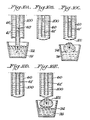
- this probe assembly having a moveable inner conduit may be better understood by reference to Figs. 10A-E. As will be seen, this operation is very much the same as that described for the fixed inner conduit. For this reason, the workings of the sample turntable 34 in conjunction with the raising and lowering of the conduits 60 and 61' all under the control of the generator 20 and controller 22 will be omitted.
- FIG. 10A there is seen a coaxial pipetting system with the moveable inner conduit 61 in a protruding position and the probe assembly lowered so that the inner conduit drops into a sample container 76.
- a sample aliquot can be drawn into the inner conduit 61' alone.
- This sample aliquot is typically separated from the diluent or wash liquid by an air bubble interface 62 as previously described.
- the inner conduit 61' is retracted to a position as illustrated in Fig. 10B in which the inner conduit 61' is within the outer conduit 62 so that the tip of inner conduit 61' is surrounded by diluent or wash liquid. In this position the sample liquid adheres to the outer surface of the inner conduit 61'.
- a desired quantity of sample liquid 76 is expressed from the inner conduit 61', which is still in the withdrawn position, as shown in Figure 10E, directly into the diluent liquid in the annular space.
- the resulting droplet mixture 101, Fig. 10E is washed into a reaction chamber 74 by the action of liquid 100 passing through the annular space between the inner and outer conduits 60-61'.
- a coaxial pipetting system, with a moveable inner conduit was constructed using an inner conduit 61 made from a 24 inch long section of 21 ga. thin wall stainless steel needle tubing (part number HTX-21 TW SS 403 from Small Parts, Inc., Miami, Florida 33138).
- the tip was swaged to reduce the inner diameter from 0.023 inch to 0.010 inch and ground flat and approximately normal to the long axis.
- the outer conduit 60 a 1 inch long, 18ga. needle - (Becton Dickinson, Rutherford, N.J., Cournand Needle, catalog #1268), which was also ground flat on the tip but not swaged.
- the coaxial needle assembly was then mounted in the probe housing 49 as shown in Figure 5.
- the inner conduit was calculated to contain 70 microliters of fluid.
- the long length of inner needle tubing was used to avoid junctions which have dead volumes which contribute to carry-over of one sample to the next, causing cross--contaminations.
- the use of a larger bore tubing would help reduce the length.
- it is desirable to minimize the size of the orifice at the tip since the reproducibility of the sample liquid boundary is on the order of a hemisphere with a diameter equal to the diameter of the orifice.
- the swaging operation achieves a compromise.
- long tubing with a narrow bore will have a very large and undesirable pressure drop even at moderate liquid flow rates.
- the sample pump 24 was filled to 50% capacity with water.
- the valve 38 was switched to the inner conduit and the pump withdrew 1 microliter air, 1 microliter dye, 1 microliter air, and 25 microliter dye.
- the dye in a small container was manually lifted up to the protruding inner conduit 62 until the conduit was about 5 millimeters submerged.
- the inner conduit was withdrawn and 1 microliter expelled from the inner conduit 61 into the annular space and 100 microliters of water flushed through the annular space.
- the amount of water hanging from the outer conduit 60 was controlled by touching the needle to the side of the receiving container.
- FIG. 7 illustrates a coaxial conduit assembly where the outer conduit 82 is of reduced diameter at the inlet tip.
- This reduced cross-sectional area provides for a higher velocity fluid flow at the inlet tip, creating a better washing of the outer surface of the inner needle and, in addition, it reduces the uncertainty of the volume dispensed of the second liquid because of a reduced miniscus.
- This configuration affords a further advantage of providing for a reduced pressure drop due to the larger outer conduit diameter 84, while maintaining a small cross section 82 at the inlet tip.
- Figure 8 illustrates a coaxial conduit assembly where the inner conduit 86 is of reduced diameter at the inlet tip. This design contains more first liquid per unit surface of the inner conduit while maintaining a small miniscus and hence small uncertainty of the interface between the first liquid and second liquid.
- Figure 9 illustrates a coaxial conduit assembly where both conduits are of reduced diameter at their inlet ends. This configuration combines the advantages of both Figure 7 and Figure 8 as defined in the above writing.
- liquid when used in this specification and claims, it is understood to include water or saline or buffer solutions, or other suitable diluting or wash liquid. In some cases, it may be a reagent solution although this can cause undesired or premature reactions to occur.
- the system provides for better volumetric repeatability since the sample is directly dispensed into a miscible carrier fluid (diluent or wash liquid), thus eliminating the uncertainty associated with surface tension effects and drop adhesion to the needle tip.
- a miscible carrier fluid diiluent or wash liquid
- sample-to-sample contamination is minimized.
- the inner conduit is free to slideably move relative to the inner conduit providing for easy sample access. There is less sample waste due to the smaller surface area wetted by the sample.
- the external surface of the outer conduit is never in contact with the sample, thereby reducing contamination.
- a variety of inner and outer conduit diameter combinations provide for reduced cross-sectional area at the tip of the orifice, thereby minimizing the interfacial surface of the liquid therein contained while at the same time minimizing peripheral surface area contact with the inner conduit.
Landscapes
- Physics & Mathematics (AREA)
- Health & Medical Sciences (AREA)
- Life Sciences & Earth Sciences (AREA)
- Chemical & Material Sciences (AREA)
- Analytical Chemistry (AREA)
- Biochemistry (AREA)
- General Health & Medical Sciences (AREA)
- General Physics & Mathematics (AREA)
- Immunology (AREA)
- Pathology (AREA)
- Automatic Analysis And Handling Materials Therefor (AREA)
- Sampling And Sample Adjustment (AREA)
Applications Claiming Priority (2)
| Application Number | Priority Date | Filing Date | Title |
|---|---|---|---|
| US06/692,409 US4574850A (en) | 1985-01-17 | 1985-01-17 | Method of and apparatus for dispensing liquid |
| US692409 | 1985-01-17 |
Publications (3)
| Publication Number | Publication Date |
|---|---|
| EP0188265A2 true EP0188265A2 (de) | 1986-07-23 |
| EP0188265A3 EP0188265A3 (en) | 1987-06-10 |
| EP0188265B1 EP0188265B1 (de) | 1992-04-01 |
Family
ID=24780469
Family Applications (1)
| Application Number | Title | Priority Date | Filing Date |
|---|---|---|---|
| EP86100381A Expired EP0188265B1 (de) | 1985-01-17 | 1986-01-14 | Verfahren zur Flüssigkeitsspende |
Country Status (8)
| Country | Link |
|---|---|
| US (1) | US4574850A (de) |
| EP (1) | EP0188265B1 (de) |
| JP (1) | JPH0795013B2 (de) |
| CA (1) | CA1262708A (de) |
| DE (1) | DE3684613D1 (de) |
| DK (1) | DK20486A (de) |
| GR (1) | GR860094B (de) |
| IE (1) | IE860111L (de) |
Cited By (6)
| Publication number | Priority date | Publication date | Assignee | Title |
|---|---|---|---|---|
| EP0438136A3 (en) * | 1990-01-18 | 1992-01-22 | Mochida Pharmaceutical Co., Ltd. | Automated dispensing and diluting system |
| DE4203638A1 (de) * | 1992-02-08 | 1993-08-12 | Boehringer Mannheim Gmbh | Fluessigkeitstransfereinrichtung fuer ein analysegeraet |
| DE4318919A1 (de) * | 1993-06-07 | 1994-12-08 | Bodenseewerk Perkin Elmer Co | Probendosiersystem |
| WO2010133965A3 (en) * | 2009-05-19 | 2011-05-26 | Stokes Bio Limited | Sampling device |
| US8697011B2 (en) | 2009-05-19 | 2014-04-15 | Stokes Bio Limited | Sampling device with immiscible fluid supply tube in counter-flow arrangement |
| US8741660B2 (en) | 2009-05-19 | 2014-06-03 | Stokes Bio Limited | Sampling device |
Families Citing this family (37)
| Publication number | Priority date | Publication date | Assignee | Title |
|---|---|---|---|---|
| US4871682A (en) * | 1986-04-30 | 1989-10-03 | Baxter Travenol Laboratories, Inc. | Diluent carryover control |
| US4911212A (en) * | 1987-07-06 | 1990-03-27 | Burton John W | Bottle filling device |
| DE3881709T2 (de) * | 1988-06-27 | 1993-11-04 | John W Burton | Flaschenabfuellanordnung. |
| US5130095A (en) * | 1989-03-13 | 1992-07-14 | Beckman Instruments, Inc. | Automatic chemistry analyzer |
| US5132233A (en) * | 1989-03-13 | 1992-07-21 | Beckman Instruments, Inc. | Sample injection cell |
| US4984475A (en) * | 1989-07-24 | 1991-01-15 | Tritech Partners | Ultra low carryover sample liquid analysis apparatus and method |
| US4989623A (en) * | 1989-12-01 | 1991-02-05 | Akzo N.V. | Apparatus and method for cleaning reagent delivery probes |
| US5133373A (en) * | 1989-12-01 | 1992-07-28 | Akzo N.V. | Apparatus and method for cleaning reagent delivery probes |
| US5646046A (en) * | 1989-12-01 | 1997-07-08 | Akzo Nobel N.V. | Method and instrument for automatically performing analysis relating to thrombosis and hemostasis |
| US5141871A (en) * | 1990-05-10 | 1992-08-25 | Pb Diagnostic Systems, Inc. | Fluid dispensing system with optical locator |
| US5133392A (en) * | 1991-04-10 | 1992-07-28 | Eastman Kodak Company | Liquid injection using container bottom sensing |
| CA2074400A1 (en) * | 1992-07-22 | 1994-01-23 | E. Brent Cragun | Beverage dispensing apparatus and process |
| US5310685A (en) * | 1992-09-02 | 1994-05-10 | Dow Corning Corporation | Apparatus for delivering a calibration standard |
| JP3239199B2 (ja) * | 1993-12-20 | 2001-12-17 | シスメックス株式会社 | ピペット洗浄装置 |
| JP3572792B2 (ja) * | 1996-04-04 | 2004-10-06 | 東ソー株式会社 | 前処理装置 |
| US6083762A (en) * | 1996-05-31 | 2000-07-04 | Packard Instruments Company | Microvolume liquid handling system |
| EP1099484B1 (de) | 1999-11-11 | 2006-06-07 | The Provost, Fellows And Scholars Of The College Of The Holy And Undivided Trinity Of Queen Elizabeth Near Dublin | Vorrichtung und Verfahren zur Verabreichung von Tropfen |
| US6709872B1 (en) * | 2000-05-02 | 2004-03-23 | Irm Llc | Method and apparatus for dispensing low nanoliter volumes of liquid while minimizing waste |
| US6669909B2 (en) | 2001-03-26 | 2003-12-30 | Allegro Technologies Limited | Liquid droplet dispensing |
| US20020168297A1 (en) * | 2001-05-11 | 2002-11-14 | Igor Shvets | Method and device for dispensing of droplets |
| US20030175163A1 (en) * | 2002-03-18 | 2003-09-18 | Igor Shvets | Multiple dispenser |
| US7247487B2 (en) * | 2003-06-18 | 2007-07-24 | Ortho-Clinical Diagnostics | Reducing working fluid dilution in liquid systems |
| DE10342304B4 (de) * | 2003-09-12 | 2006-02-02 | Agilent Technologies, Inc. (n.d.Ges.d.Staates Delaware), Palo Alto | Rüssel zur Entnahme und/oder Zufuhr einer Flüssigkeit |
| US7396512B2 (en) * | 2003-11-04 | 2008-07-08 | Drummond Scientific Company | Automatic precision non-contact open-loop fluid dispensing |
| EP1776592A1 (de) * | 2004-07-22 | 2007-04-25 | Amgen, Inc | Verfahren und vorrichtung zur bildung einer verdünnung durch flüssigkeitsdispersion |
| US20060258011A1 (en) | 2005-04-22 | 2006-11-16 | Igor Shvets | Cleaning of system for dispensing of liquid droplets |
| WO2007024798A2 (en) * | 2005-08-22 | 2007-03-01 | Applera Corporation | Apparatus, system, and method using immiscible-fluid-discrete-volumes |
| DE102006017360A1 (de) * | 2006-04-11 | 2007-10-18 | Diasys Diagnostic Systems Gmbh | Verfahren zum Dosieren und Mischen |
| EP1946843A1 (de) * | 2006-12-21 | 2008-07-23 | Allegro Research Limited | Vorrichtung und Verfahren zum Überwachen und Messen von Tröpfchen |
| JP2008298493A (ja) * | 2007-05-30 | 2008-12-11 | Hitachi High-Technologies Corp | 自動分析装置 |
| JP4538477B2 (ja) * | 2007-08-31 | 2010-09-08 | 株式会社日立ハイテクノロジーズ | 自動分析装置 |
| WO2011120020A1 (en) * | 2010-03-25 | 2011-09-29 | Quantalife, Inc. | Droplet transport system for detection |
| EP2193847A1 (de) * | 2008-12-04 | 2010-06-09 | EMBL (European Molecular Biology Laboratory) | Koaxialnadel und Pipettiervorrichtung |
| US8347925B2 (en) * | 2009-08-19 | 2013-01-08 | Institute Of Nuclear Energy Research | Automatic filling machine for radiopharmaceuticals |
| EP2848306B1 (de) | 2013-09-13 | 2016-04-06 | Bruker Daltonik GmbH | Spendersystem für massenspektrometrische Probenzubereitungen |
| US10807117B2 (en) * | 2015-10-05 | 2020-10-20 | Tokyo Electron Limited | Dispense nozzle with a dynamic liquid plug |
| WO2026017933A1 (fr) * | 2024-07-17 | 2026-01-22 | Biomerieux | Dispositif pour le remplissage d'une cavité d'une carte d'analyse |
Family Cites Families (16)
| Publication number | Priority date | Publication date | Assignee | Title |
|---|---|---|---|---|
| US3804593A (en) * | 1964-05-25 | 1974-04-16 | Technicon Instr | Automatic analysis apparatus and method |
| US3484170A (en) * | 1966-04-14 | 1969-12-16 | Technicon Corp | Automatic analysis method and apparatus |
| US3479141A (en) * | 1967-05-17 | 1969-11-18 | Technicon Corp | Method and apparatus for analysis |
| US3764041A (en) * | 1970-10-26 | 1973-10-09 | Searle & Co | Microdispensing process and apparatus |
| US3795149A (en) * | 1971-10-15 | 1974-03-05 | Technicon Instr | Method and apparatus for supplying samples for automated analysis |
| US3869068A (en) * | 1974-06-06 | 1975-03-04 | Hyperion Inc | Diluter probe assembly |
| US3960020A (en) * | 1974-12-30 | 1976-06-01 | Technicon Instruments Corporation | Liquid aspirating probe assembly of a supply analyzer |
| GB1553592A (en) * | 1976-06-10 | 1979-09-26 | Technicon Instr | Sample supply apparatus |
| US4121466A (en) * | 1977-04-19 | 1978-10-24 | Technicon Instruments Corporation | Liquid dispenser with an improved probe |
| FI55910C (fi) * | 1978-01-10 | 1979-10-10 | Suovaniemi Finnpipette | Anordning foer inboerdes noggrann dosering och utspaedning av vaetskor |
| JPS54116900A (en) * | 1978-03-02 | 1979-09-11 | Nittan Co Ltd | Alarm control system |
| US4259291A (en) * | 1979-07-13 | 1981-03-31 | Technicon Instruments Corporation | Metering device |
| US4318885A (en) * | 1979-09-10 | 1982-03-09 | Olympus Optical Co., Ltd. | Liquid treating device for chemical analysis apparatus |
| JPS5639455A (en) * | 1979-09-10 | 1981-04-15 | Olympus Optical Co Ltd | Method and device for measuring ion concentration |
| US4367043A (en) * | 1980-05-05 | 1983-01-04 | Leland Stanford Junior University | Method and means for delivering liquid samples to a sample scanning device |
| JPS5736542A (de) * | 1980-08-13 | 1982-02-27 | Matsushita Electric Works Ltd |
-
1985
- 1985-01-17 US US06/692,409 patent/US4574850A/en not_active Expired - Lifetime
-
1986
- 1986-01-14 EP EP86100381A patent/EP0188265B1/de not_active Expired
- 1986-01-14 DE DE8686100381T patent/DE3684613D1/de not_active Expired - Lifetime
- 1986-01-15 IE IE860111A patent/IE860111L/xx unknown
- 1986-01-15 GR GR860094A patent/GR860094B/el unknown
- 1986-01-16 JP JP61005177A patent/JPH0795013B2/ja not_active Expired - Lifetime
- 1986-01-16 DK DK20486A patent/DK20486A/da not_active Application Discontinuation
- 1986-01-16 CA CA000499707A patent/CA1262708A/en not_active Expired
Cited By (8)
| Publication number | Priority date | Publication date | Assignee | Title |
|---|---|---|---|---|
| EP0438136A3 (en) * | 1990-01-18 | 1992-01-22 | Mochida Pharmaceutical Co., Ltd. | Automated dispensing and diluting system |
| US5158748A (en) * | 1990-01-18 | 1992-10-27 | Mochida Pharmaceutical Co., Ltd. | Automated dispensing and diluting system |
| DE4203638A1 (de) * | 1992-02-08 | 1993-08-12 | Boehringer Mannheim Gmbh | Fluessigkeitstransfereinrichtung fuer ein analysegeraet |
| DE4318919A1 (de) * | 1993-06-07 | 1994-12-08 | Bodenseewerk Perkin Elmer Co | Probendosiersystem |
| WO2010133965A3 (en) * | 2009-05-19 | 2011-05-26 | Stokes Bio Limited | Sampling device |
| US8697011B2 (en) | 2009-05-19 | 2014-04-15 | Stokes Bio Limited | Sampling device with immiscible fluid supply tube in counter-flow arrangement |
| US8741660B2 (en) | 2009-05-19 | 2014-06-03 | Stokes Bio Limited | Sampling device |
| US9387472B2 (en) | 2009-05-19 | 2016-07-12 | Stokes Bio Limited | Sampling device |
Also Published As
| Publication number | Publication date |
|---|---|
| DK20486A (da) | 1986-07-18 |
| GR860094B (en) | 1986-05-14 |
| JPH0795013B2 (ja) | 1995-10-11 |
| EP0188265B1 (de) | 1992-04-01 |
| CA1262708A (en) | 1989-11-07 |
| EP0188265A3 (en) | 1987-06-10 |
| JPS61169736A (ja) | 1986-07-31 |
| IE860111L (en) | 1986-07-17 |
| US4574850A (en) | 1986-03-11 |
| DE3684613D1 (de) | 1992-05-07 |
| DK20486D0 (da) | 1986-01-16 |
Similar Documents
| Publication | Publication Date | Title |
|---|---|---|
| US4574850A (en) | Method of and apparatus for dispensing liquid | |
| US4323537A (en) | Analysis system | |
| US5408891A (en) | Fluid probe washing apparatus and method | |
| US4888998A (en) | Sample handling system | |
| US4228831A (en) | Probe and syringe drive apparatus | |
| EP0408270B1 (de) | Pipette, Pipettenrohr, diese verwendendes Probenanalysegerät und Verfahren zur Mischung und Pipettierung von Flüssigkeiten | |
| US4836038A (en) | Automated sampler-injector apparatus and method for sampling a quantity of sample and testing portions of said quantity | |
| EP1056541B1 (de) | System und verfahren zur abgabe eines reagenzes | |
| US6382035B1 (en) | Multi-valving sample injection apparatus | |
| CA2019517C (en) | Sample liquid aspirating and dispensing probe | |
| US3900289A (en) | Apparatus and method for filling a compartment | |
| EP1766418B1 (de) | Sondenwaschgefässe und -verfahren | |
| US3991616A (en) | Automatic pipetter | |
| CA2200918A1 (en) | Sample dilution module | |
| EP0825446B1 (de) | Pipettenreinigungseinheit für automatische biochemische Analysiervorrichtung | |
| CA2493611C (en) | Metering tip with internal features to control fluid meniscus and fluid oscillation | |
| EP0253519B1 (de) | Probenhandhabungsvorrichtung | |
| US3817425A (en) | Chemical dispenser | |
| JPS6366466A (ja) | デイスクリ−ト型自動分析装置 | |
| US10768192B2 (en) | Device and method to sample liquids with high-precision in an automated sample analyzer | |
| EP1335853B1 (de) | flüssigkeitsspender für proben ohne kreuzkontamination | |
| JP7495867B2 (ja) | 自動分析装置 | |
| US20050197538A1 (en) | Reagent and sample introduction plunger device for a syringe | |
| JPH02134568A (ja) | 液体分注装置 | |
| CN114323783A (zh) | 一种采样方法、采样组件以及样本分析仪 |
Legal Events
| Date | Code | Title | Description |
|---|---|---|---|
| PUAI | Public reference made under article 153(3) epc to a published international application that has entered the european phase |
Free format text: ORIGINAL CODE: 0009012 |
|
| AK | Designated contracting states |
Kind code of ref document: A2 Designated state(s): BE DE FR GB IT LU NL |
|
| PUAL | Search report despatched |
Free format text: ORIGINAL CODE: 0009013 |
|
| AK | Designated contracting states |
Kind code of ref document: A3 Designated state(s): BE DE FR GB IT LU NL |
|
| 17P | Request for examination filed |
Effective date: 19871204 |
|
| 17Q | First examination report despatched |
Effective date: 19900108 |
|
| GRAA | (expected) grant |
Free format text: ORIGINAL CODE: 0009210 |
|
| AK | Designated contracting states |
Kind code of ref document: B1 Designated state(s): BE DE FR GB IT LU NL |
|
| ET | Fr: translation filed | ||
| ITF | It: translation for a ep patent filed | ||
| REF | Corresponds to: |
Ref document number: 3684613 Country of ref document: DE Date of ref document: 19920507 |
|
| PG25 | Lapsed in a contracting state [announced via postgrant information from national office to epo] |
Ref country code: GB Effective date: 19930114 |
|
| PG25 | Lapsed in a contracting state [announced via postgrant information from national office to epo] |
Ref country code: LU Free format text: LAPSE BECAUSE OF NON-PAYMENT OF DUE FEES Effective date: 19930131 Ref country code: BE Effective date: 19930131 |
|
| PLBE | No opposition filed within time limit |
Free format text: ORIGINAL CODE: 0009261 |
|
| STAA | Information on the status of an ep patent application or granted ep patent |
Free format text: STATUS: NO OPPOSITION FILED WITHIN TIME LIMIT |
|
| 26N | No opposition filed | ||
| BERE | Be: lapsed |
Owner name: E.I. DU PONT DE NEMOURS AND CY Effective date: 19930131 |
|
| PG25 | Lapsed in a contracting state [announced via postgrant information from national office to epo] |
Ref country code: NL Effective date: 19930801 |
|
| GBPC | Gb: european patent ceased through non-payment of renewal fee |
Effective date: 19930114 |
|
| NLV4 | Nl: lapsed or anulled due to non-payment of the annual fee | ||
| REG | Reference to a national code |
Ref country code: FR Ref legal event code: TP |
|
| REG | Reference to a national code |
Ref country code: FR Ref legal event code: TP Ref country code: FR Ref legal event code: CD |
|
| PGFP | Annual fee paid to national office [announced via postgrant information from national office to epo] |
Ref country code: FR Payment date: 20001220 Year of fee payment: 16 Ref country code: DE Payment date: 20001220 Year of fee payment: 16 |
|
| PG25 | Lapsed in a contracting state [announced via postgrant information from national office to epo] |
Ref country code: DE Free format text: LAPSE BECAUSE OF NON-PAYMENT OF DUE FEES Effective date: 20020801 |
|
| PG25 | Lapsed in a contracting state [announced via postgrant information from national office to epo] |
Ref country code: FR Free format text: LAPSE BECAUSE OF NON-PAYMENT OF DUE FEES Effective date: 20020930 |
|
| REG | Reference to a national code |
Ref country code: FR Ref legal event code: ST |
|
| PG25 | Lapsed in a contracting state [announced via postgrant information from national office to epo] |
Ref country code: IT Free format text: LAPSE BECAUSE OF NON-PAYMENT OF DUE FEES;WARNING: LAPSES OF ITALIAN PATENTS WITH EFFECTIVE DATE BEFORE 2007 MAY HAVE OCCURRED AT ANY TIME BEFORE 2007. THE CORRECT EFFECTIVE DATE MAY BE DIFFERENT FROM THE ONE RECORDED. Effective date: 20050114 |