EP0188281B1 - Leuchtvorrichtung, insbesondere für Kerzen - Google Patents
Leuchtvorrichtung, insbesondere für Kerzen Download PDFInfo
- Publication number
- EP0188281B1 EP0188281B1 EP86100452A EP86100452A EP0188281B1 EP 0188281 B1 EP0188281 B1 EP 0188281B1 EP 86100452 A EP86100452 A EP 86100452A EP 86100452 A EP86100452 A EP 86100452A EP 0188281 B1 EP0188281 B1 EP 0188281B1
- Authority
- EP
- European Patent Office
- Prior art keywords
- light fixture
- intermediary
- locking means
- candlearms
- annular
- Prior art date
- Legal status (The legal status is an assumption and is not a legal conclusion. Google has not performed a legal analysis and makes no representation as to the accuracy of the status listed.)
- Expired - Lifetime
Links
Images


Classifications
-
- F—MECHANICAL ENGINEERING; LIGHTING; HEATING; WEAPONS; BLASTING
- F21—LIGHTING
- F21S—NON-PORTABLE LIGHTING DEVICES; SYSTEMS THEREOF; VEHICLE LIGHTING DEVICES SPECIALLY ADAPTED FOR VEHICLE EXTERIORS
- F21S13/00—Non-electric lighting devices or systems employing a point-like light source; Non-electric lighting devices or systems employing a light source of unspecified shape
Definitions
- the invention relates to a light fixture such as a candelabrum preferably for candlelight in accordance with the preamble of claim 1.
- US-A-3 745 330 discloses a light fixture of this type in which each candlearm made of pipe material is turnable, however, fastened in certain position.
- the fastening means is constituted by a cylindrical shell having discs at each end. These discs have holes for the candlearms.
- the cylindrical shell is of a relatively large diameter, because it contains a plurality of electrical conduits extending out through the arms to electric lamps. The fact that the cylindrical shell has a large diameter means that the candleholder when in flattened state and with the locking means removed will take relatively much space. Furthermore it is rather complex and expensive to produce.
- German Patent Specification No. 51 41 61 discloses a light fixture in the form of a two-armed candelabrum for candlelights whereby the arms of the candelabrum are formed integral with a foot and interconnected symmetrically relative to a vertical axis.
- the arms of the candelabrum are rigidly interconnected by means of metal wires in such a manner that a candelabrum is formed which cannot be folded. Consequently, the candelabrum takes up relatively much room when it is to be put away or transported.
- Swedish Patent Specification No. 136002 describes also a light fixture of the above type. It is a question of a light fixture comprising two vertical plates provided with candlelight holders and a centrally positioned vertical slot in the uppermost portion of one plate and in the lowermost portion respectively, of the second plate. By moving the vertical plates of the light fixture away from one another it is possible to transport and put away, respectively, said flattened plates. An essential draw-back applies, however, as the flattened candelabrum does not remain as a unit, said candelabrum comprising several removable parts which are easily lost.
- the object of the present invention is to provide a light fixture such as a candelabrum of the above type and which apart from one or more locking means comprises no loose parts, and which implies that by removing the locking means the individual candlelight arms of the light fixture can be folded towards one another instead of being secured in predetermined angular positions whereby the light fixture can be flattened when not used.
- the invention provides a candelabrum-type light fixture for candles comprising a plurality of candlearms, each candlearm comprising a first and a second end part as well as a plurality of intermediary parts, the fixture comprising a separate holder, by means of which all the candlearms are pivotably secured to one another around a vertical axis of symmetry, and each candlearm being lockable in predetermined angular positions by means of at least one removable annular locking means, when the light fixture is in use, and freely rotatable around the axis of symmetry and thus foldable towards one another in such manner that the light fixture is flattened, when the locking means has been removed, and is characterized in that the candlearms are manufactured of metal wire, that the locking means are manufactured of bent metal wire, that each.candlearm has an elongate intermediary part, that the holder is manufactured from metal wire and comprises a rectilinear and rigid intermediary portion aligned parallel to the vertical symmetry axis when the fixture is in use, as well as an
- the candlelight arms are turned from the flattened state and into the positions adjacent the predetermined angular positions. Subsequently, one or more locking means are situated in locking engagement with the candlelight arms which are thereby positioned and retained in the predetermined angular positions.
- light sources such as candlelights can be situated in all the candlelight holders of the candlelight arms.
- the candlelight arms can be turned freely about the symmetrical axis upon removal of the locking means and thereby be folded towards one another so as to allow a flattening of the light fixture.
- the light fixture requires only little room which is an advantage both with respect to transport and with respect to putting away. Beyond the annular locking means the light fixture is advantageously free of loose parts.
- All the parts of the light fixture may in a simple manner be made of metal wire.
- the locking means may be situated on a plane perpendicular to the symmetrical axis.
- Each candlelight arm of the light fixture comprises a first and a second end part as well as a plurality of intermediary parts, whereby the first end part may comprise a substantially vertical preferably slightly conical, -and optionally helically shaped candlelight holder, one of the intermediary parts of each candlelight arm being bent, so as to form one or more indents, each constituting a boundary between two neighbouring intermediary parts, said indents engaging the annular locking means, and all the candlelight holders may be situated on one plane perpendicular to the symmetrical axis.
- the locking means may be formed by a plurality of curved portions linked by cusps, each adapted to lockingly engage the indent of a candlelight arm, and a number of cusps may at least correspond to the number of candlelight arms. In this manner the locking means can be very simply manufactured at the same time as the above good retaining of the candlelight arms in the predetermined angular positions is ensured.
- each candlelight arm may be formed as a hook means and engage an associated locking part on a second annular locking means serving as foot for the light fixture, said second annular locking means being of such a great diameter that the light fixture stands reliably firmly on a supporting surface, and whereby the number of associated locking parts at least corresponds to the number of candlelight arms.
- the light fixture optionally formed as a candelabrum can be situated on a tabletop or the like base.
- each candlelight arm may comprise a candlelight holder too, and each candlelight arm may comprise two bulges, whereby the manufacturing of the light fixture is simple in spite of the number of light sources, as it comprises relatively few parts.
- the candlelight holder of the first end part may be situated on the same horizontal plane as the candlelight holder of the second end part, and all the bulges of the candlelight arms may engage the same annular locking means, whereby all the candlelight holders are situated on the same plane allowing a particularly simple embodiment of the candelabrum.
- the candlelight holder of the first end part may be situated on a different horizontal plane compared to the plane on which the candlelight holder of the second end part is positioned, and the two bulges of each candlelight arm may engage their respective annular locking means.
- the light fixture is shaped as a candelabrum with candlelight holders positioned on several superjacent planes, and the candelabrum is then particularly decorative.
- the holder may at the uppermost annular position be upwardly extended and end in a ring or hook for the suspension of the chandelier, whereby the light fixture is shaped as a chandelier suspend- able in a particularly simple manner.
- the holder may at the lowermost annular portion be downwardly extended and end in a ring or a hook engaging a supporting member such as for instance an iron ball with a foot, whereby the candelabrum for instance can be situated on a table with the foot resting on the tabletop.
- a supporting member such as for instance an iron ball with a foot
- the candelabrum can for instance be situated on a table or the iron ball can have a decorative effect through the suspension of the candelabrum.
- the light fixture may be shaped as a candelabrum with an arbitrary number of candlelight arms comprising candlelight holders on one or two superjacent planes.
- the candelabrum may be decorated in many different ways in response to the use in question.
- the candlelight holders may be shaped in other ways than the above, and on top of each holder for instance a slightly conical ring can be arranged through which the candlelight is inserted in the candlelight holder.
- This ring is decorative and it collects the stearin running down the candle when said candle is lit.
- the holder As the holder is very elongated and narrow it requires relatively little room when the fixture is folded as well as it assists in ensuring a reliable retaining of the candlelight arms in their angular positions when the fixture is used. The retaining is efficient even in case the candlelights are rather heavy.
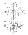
- the light fixture 1 of Figure 1 is shaped as a chandelier, but may also be shaped as a candelabrum comprising four candlelight arms 2, an annular locking means 6 as well as a holder 5.
- the candlelight arms 2 are pivotably interconnected by means of the holder 5 about a vertical symmetrical axis 3.
- Each candlelight arm 2 comprises a first end part 11, a second end part 12, as well as intermediary parts 13, 16, 17, 18 positioned between said first end part 11 and said second end part 12.
- the intermediary part 13 is elongated and extends substantially parallel to the vertical symmetrical axis 2, cf.
- Figure 2 comprises a rectilinear intermediary portion 8 and an annular portion 9 shaped at each of the intermediary portion 8.
- the annular portion 9 grips about all the elongated intermediary parts 13 of the candlelight arms 2.
- the rectilinear portion 8 is of almost the same extent along the symmetrical axis 3 as the elongated intermediary parts 13 of the candlelight arms 2, cf. Figure 5.
- the annular locking means 6 is formed by four curved portions 31 continuing into one another at four transitions 32.
- each candlelight arm 2 comprises furthermore a bulge 30 between the intermediary parts 17 and 18.
- the bulges 30 engage the transitions 32 of the annular locking means when the candlelight arms to be locked in predetermined angular positions when the light fixture 1 is to be used.
- the locking means 6 is positioned on a plane perpendicular to the symmetrical axis 3.
- the annular locking means 6 is removed whereafter the candlelight arms 2 turnable about the vertical symmetrical axis 3 are folded towards one another, cf. the arrows A of Figure 1, in such a manner that the candelabrum 1 is flattened.
- the flattened state of the holders is indicated by a dotted line in Figure 1. In this manner the light fixture 1 requires very little room when put away or transported. Thus it is easy to transport the light fixture in a flat bag.
- each candlelight arm 2 comprises a vertical candle holder 21 situated at the first end part 11 of said arm, said holder preferably being slightly conical and optionally helically shaped.
- the intermediary parts 16, 17 extend into one another and are by this embodiment shaped in a simple manner like two semicircles. Via the bulge 30 the intermediary part 17 continues into the intermediary part 18 in turn extending parallel to the vertical symmetrical axis 3. Subsequently, the intermediary part 18 extends via a curved portion preferably formed by a quarter-circle into the intermediary part 13 parallel to the symmetrical axis 3.
- the intermediary part 13 ends in a hook 20 gripping about the uppermost annular portion 9 of the holder 5.
- the upper end of the holder 5 continues into a ring 10 suitable for the suspension of the light fixture in such a manner that said light fixture serves as a chandelier.
- the lower end of the holder 5 may continue into a hook 14 allowing suspension of for instance a decorative article such as a ball 15 or the like.
- the hook 14 allows furthermore a suspension of a second chandelier 1 according to the invention and with a ring 10 for the suspension in such a manner that the chandeliers are vertically suspended above one another.
- Figures 3 and 4 illustrate a second embodiment of the light fixture 1 according to the invention.
- the candelabrum 1 comprises two annular locking means 6.
- Each locking means 6 is formed by five curved portions 31 with five transitions 32.
- the light fixture 1 comprises five candlelight arms 2, each arm comprising two candle holders 21, 22.
- One holder 21 is shaped integral with the first end part 11, and the second holder 22 is shaped integral with the second end part 12. All the candle holders 21 are positioned on the same horizontal plane C positioned vertical above the second horizontal plane B in which all the holders 22 are positioned.
- Figure 3 only illustrates one of the holders 21 and one of the holders 22, and the right of Figure 4 illustrates only part of a second candlelight arm 2 for the sake of clarity.
- Each candlelight arm 2 of the light fixture of Figures 3 and 4 is shaped in the following manner:
- the holder 21 extends into an intermediary part 16 shaped as a semicircle and continuing into an intermediary part 17 also shaped as a semicircle.
- the intermediary part 17 extends via a bulge 30 into an intermediary part 18 preferably shaped as a quarter circle and extending into the intermediary part 13 extending parallel to the symmetrical axis 3.
- the latter intermediary part 13 extends into a second intermediary part 18 continuing via a second bulge 33 into a second intermediary part 17 in turn extending into a second intermediary part 16 ending in the second holder 22.
- the intermediary parts of the embodiment shown situated above the intermediary part 13 of each candlelight arm 2 form an angle of about 36° with the intermediary parts of the candlelight arm 2 below the intermediary part 13, cf. Figure 3.
- the fixture 1 is manufactured in a more simple manner and it comprises advantageously less loose parts than previously before said loose parts are assembled by means of the holder 5.
- Figure 5 illustrates a portion of the holder 5.
- This holder 5 may, however, be shaped in several other ways such as for instance like a tube.
- FIG. 6 illustrates a third embodiment of the light fixture according to the invention, said third embodiment, however, corresponding to the embodiment of Figure 4 concerning the form of the candlelight arms 2.
- This embodiment appears with three candlelight arms provided with holders 21, 22 positioned on two different planes.
- a ring 35 is situated on top of each candle holder 21, 22, said ring upwardly being slightly conical.
- each candle 4 is to be inserted when it is to be placed in the holder 21, 22. Beyond the decorative effect the ring 35 can collect the stearin running down the candle 4.
- the intermediary parts 16, 17, 18 of the candlelight arms 2 may be formed in a manner differing from the embodiment of Figure 6 whereby the intermediary parts 18 extend downwards before they continue into the intermediary parts 17 via the bulges.
- the light fixture 1 comprises only a lower hook 14 for instance engaging an iron ball 15 in such a manner that the light fixture 1 cn be situated on a permanent supporting surface such as a table.
- FIG 8 illustrates a fifth embodiment of the light fixture 1 according to the invention and with five candlelight arms 2.
- Each candlelight arm 2 comprises a candle holder 21, all said holders 21 being positioned on the same plane.
- the intermediary part 19 of each candlelight arm 2 is situated below the intermediary part 13 of the arm 2 extending parallel to the symmetrical axis 3 and is preferably shaped as a quarter circle of a great radius compared to the radius of the remaining intermediary parts 16, 17, 18.
- the other end part 12 of the candlelight arm 2 is preferably shaped as a hook means 40 engaging the locking members 41 of a second locking means 7.
- the locking means 7 is of a relatively great diameter, whereby a foot is provided on the light fixture 1 in such a manner that said fixture can stand firmly and reliably on a table.
- the light fixture 1 can be used for many different purposes. It may for instance be provided with four candlelight arms and thereby be used in connection with or for a Christmas advent garland.
- the particularly advantageous embodiment of the fixture i.e. that the arms can be folded towards one another after removal of the locking means, implies that it is easy to transport and for instance to bring along in a rucksack or the like.
- the candelabrum can be provided with an almost arbitrary number of arms and with holders positioned on one or two different planes.
- the intermediary parts of the arms may be shaped with many differet geometric shapes and the candelabrum may be placed on a table or as a chandelier.
- the light fixture may be made of many different materials. The important feature is, however, that the arms are maintained so as to be rotatable about a symmetrical axis and furthermore that they can be retained in predetermined angular positions by means of one or more locking means.
- the holder 5 is of a length corresponding to substantially 9 times the diameter of the annular portions 9, especially the uppermost portion 9.
Landscapes
- Engineering & Computer Science (AREA)
- General Engineering & Computer Science (AREA)
- Arrangement Of Elements, Cooling, Sealing, Or The Like Of Lighting Devices (AREA)
- Fats And Perfumes (AREA)
- Non-Portable Lighting Devices Or Systems Thereof (AREA)
- Circuit Arrangement For Electric Light Sources In General (AREA)
- Radiation-Therapy Devices (AREA)
Claims (9)
Priority Applications (1)
| Application Number | Priority Date | Filing Date | Title |
|---|---|---|---|
| AT86100452T ATE58584T1 (de) | 1985-01-17 | 1986-01-15 | Leuchtvorrichtung, insbesondere fuer kerzen. |
Applications Claiming Priority (2)
| Application Number | Priority Date | Filing Date | Title |
|---|---|---|---|
| DK021185A DK152231C (da) | 1985-01-17 | 1985-01-17 | Flerarmet lyseholder, fortrinsvis til levende lys |
| DK211/85 | 1985-01-17 |
Publications (3)
| Publication Number | Publication Date |
|---|---|
| EP0188281A2 EP0188281A2 (de) | 1986-07-23 |
| EP0188281A3 EP0188281A3 (en) | 1988-06-22 |
| EP0188281B1 true EP0188281B1 (de) | 1990-11-22 |
Family
ID=8090989
Family Applications (1)
| Application Number | Title | Priority Date | Filing Date |
|---|---|---|---|
| EP86100452A Expired - Lifetime EP0188281B1 (de) | 1985-01-17 | 1986-01-15 | Leuchtvorrichtung, insbesondere für Kerzen |
Country Status (4)
| Country | Link |
|---|---|
| EP (1) | EP0188281B1 (de) |
| AT (1) | ATE58584T1 (de) |
| DE (1) | DE3675665D1 (de) |
| DK (1) | DK152231C (de) |
Families Citing this family (2)
| Publication number | Priority date | Publication date | Assignee | Title |
|---|---|---|---|---|
| US4993415A (en) * | 1988-08-19 | 1991-02-19 | Alliance Pharmaceutical Corp. | Magnetic resonance imaging with perfluorocarbon hydrides |
| US4951673A (en) * | 1988-08-19 | 1990-08-28 | Alliance Pharmaceutical Corp. | Magnetic resonance imaging with perfluorocarbon hydrides |
Family Cites Families (3)
| Publication number | Priority date | Publication date | Assignee | Title |
|---|---|---|---|---|
| DE514161C (de) * | 1928-03-29 | 1930-12-08 | Claessen & Cie Nachf H | Tannenzweiggebinde nach Art sogenannter Adventsleuchter |
| US3745330A (en) * | 1971-11-18 | 1973-07-10 | Frost & Son C L | Light fixture |
| FR2534665A1 (fr) * | 1982-10-18 | 1984-04-20 | Dumesny Sa Henry | Lustre demontable avec des branches porte-luminaires et un fut central forme d'un faisceau de troncons d'origine des branches, et ensembles de pieces pour constituer un tel lustre |
-
1985
- 1985-01-17 DK DK021185A patent/DK152231C/da not_active IP Right Cessation
-
1986
- 1986-01-15 EP EP86100452A patent/EP0188281B1/de not_active Expired - Lifetime
- 1986-01-15 DE DE8686100452T patent/DE3675665D1/de not_active Expired - Lifetime
- 1986-01-15 AT AT86100452T patent/ATE58584T1/de active
Also Published As
| Publication number | Publication date |
|---|---|
| EP0188281A2 (de) | 1986-07-23 |
| EP0188281A3 (en) | 1988-06-22 |
| ATE58584T1 (de) | 1990-12-15 |
| DK21185A (da) | 1986-07-18 |
| DK152231C (da) | 1988-07-04 |
| DE3675665D1 (de) | 1991-01-03 |
| DK21185D0 (da) | 1985-01-17 |
| DK152231B (da) | 1988-02-08 |
Similar Documents
| Publication | Publication Date | Title |
|---|---|---|
| US3677867A (en) | Collapsible artificial christmas tree | |
| US2151192A (en) | Flower and candle holder | |
| US4845602A (en) | Combination plant holder and light globe | |
| US3855464A (en) | Electric light-to-candle light converter | |
| US3929230A (en) | Sets of units for constructing various types of stand | |
| US20090213581A1 (en) | Lighting apparatus with candles and electric lamps | |
| US7152998B2 (en) | Assemblable string tree | |
| US3345028A (en) | Suspension device for lanterns | |
| US3168200A (en) | Tubular display stand having removable article supports | |
| EP0188281A2 (de) | Leuchtvorrichtung, insbesondere für Kerzen | |
| US20060112633A1 (en) | Illuminated plant holders | |
| US4004144A (en) | Fluorescent light unit | |
| US3137470A (en) | Bracket for mounting on a hollow post | |
| US5528479A (en) | Multiply-positioned mounting block of lighting fixture | |
| US1613386A (en) | Artificial tree | |
| EP2620053B1 (de) | Forstwirtschaftliche Beleuchtung | |
| ES2262944T3 (es) | Estructura de percha para ropa con gancho de altura variable. | |
| US7001062B2 (en) | Structure of multi-directions socket for christmas lights | |
| US4158474A (en) | Light bulb and socket combination | |
| US1257032A (en) | Combined lamp and shade holder. | |
| US8196343B1 (en) | Candlestick with annular live floral holder | |
| US11686424B2 (en) | Apparatus having plurality of stands | |
| US1857140A (en) | Flower holder | |
| JPH0321666Y2 (de) | ||
| GB2206040A (en) | Stand for a container |
Legal Events
| Date | Code | Title | Description |
|---|---|---|---|
| PUAI | Public reference made under article 153(3) epc to a published international application that has entered the european phase |
Free format text: ORIGINAL CODE: 0009012 |
|
| AK | Designated contracting states |
Kind code of ref document: A2 Designated state(s): AT BE CH DE FR GB IT LI NL SE |
|
| PUAL | Search report despatched |
Free format text: ORIGINAL CODE: 0009013 |
|
| AK | Designated contracting states |
Kind code of ref document: A3 Designated state(s): AT BE CH DE FR GB IT LI NL SE |
|
| 17P | Request for examination filed |
Effective date: 19880712 |
|
| 17Q | First examination report despatched |
Effective date: 19890808 |
|
| GRAA | (expected) grant |
Free format text: ORIGINAL CODE: 0009210 |
|
| AK | Designated contracting states |
Kind code of ref document: B1 Designated state(s): AT BE CH DE FR GB IT LI NL SE |
|
| REF | Corresponds to: |
Ref document number: 58584 Country of ref document: AT Date of ref document: 19901215 Kind code of ref document: T |
|
| ET | Fr: translation filed | ||
| REF | Corresponds to: |
Ref document number: 3675665 Country of ref document: DE Date of ref document: 19910103 |
|
| ITF | It: translation for a ep patent filed | ||
| PLBE | No opposition filed within time limit |
Free format text: ORIGINAL CODE: 0009261 |
|
| STAA | Information on the status of an ep patent application or granted ep patent |
Free format text: STATUS: NO OPPOSITION FILED WITHIN TIME LIMIT |
|
| 26N | No opposition filed | ||
| PGFP | Annual fee paid to national office [announced via postgrant information from national office to epo] |
Ref country code: GB Payment date: 19920114 Year of fee payment: 7 |
|
| PGFP | Annual fee paid to national office [announced via postgrant information from national office to epo] |
Ref country code: SE Payment date: 19920121 Year of fee payment: 7 |
|
| PGFP | Annual fee paid to national office [announced via postgrant information from national office to epo] |
Ref country code: FR Payment date: 19920127 Year of fee payment: 7 |
|
| PGFP | Annual fee paid to national office [announced via postgrant information from national office to epo] |
Ref country code: CH Payment date: 19920128 Year of fee payment: 7 Ref country code: AT Payment date: 19920128 Year of fee payment: 7 |
|
| PGFP | Annual fee paid to national office [announced via postgrant information from national office to epo] |
Ref country code: DE Payment date: 19920130 Year of fee payment: 7 |
|
| ITTA | It: last paid annual fee | ||
| PGFP | Annual fee paid to national office [announced via postgrant information from national office to epo] |
Ref country code: NL Payment date: 19920131 Year of fee payment: 7 |
|
| PGFP | Annual fee paid to national office [announced via postgrant information from national office to epo] |
Ref country code: BE Payment date: 19920212 Year of fee payment: 7 |
|
| PG25 | Lapsed in a contracting state [announced via postgrant information from national office to epo] |
Ref country code: GB Effective date: 19930115 Ref country code: AT Effective date: 19930115 |
|
| PG25 | Lapsed in a contracting state [announced via postgrant information from national office to epo] |
Ref country code: SE Effective date: 19930116 |
|
| PG25 | Lapsed in a contracting state [announced via postgrant information from national office to epo] |
Ref country code: LI Effective date: 19930131 Ref country code: CH Effective date: 19930131 Ref country code: BE Effective date: 19930131 |
|
| BERE | Be: lapsed |
Owner name: INTER-IKEA A.G. Effective date: 19930131 |
|
| PG25 | Lapsed in a contracting state [announced via postgrant information from national office to epo] |
Ref country code: NL Effective date: 19930801 |
|
| GBPC | Gb: european patent ceased through non-payment of renewal fee |
Effective date: 19930115 |
|
| NLV4 | Nl: lapsed or anulled due to non-payment of the annual fee | ||
| PG25 | Lapsed in a contracting state [announced via postgrant information from national office to epo] |
Ref country code: FR Effective date: 19930930 |
|
| REG | Reference to a national code |
Ref country code: CH Ref legal event code: PL |
|
| PG25 | Lapsed in a contracting state [announced via postgrant information from national office to epo] |
Ref country code: DE Effective date: 19931001 |
|
| REG | Reference to a national code |
Ref country code: FR Ref legal event code: ST |
|
| EUG | Se: european patent has lapsed |
Ref document number: 86100452.1 Effective date: 19930810 |
|
| PG25 | Lapsed in a contracting state [announced via postgrant information from national office to epo] |
Ref country code: IT Free format text: LAPSE BECAUSE OF NON-PAYMENT OF DUE FEES;WARNING: LAPSES OF ITALIAN PATENTS WITH EFFECTIVE DATE BEFORE 2007 MAY HAVE OCCURRED AT ANY TIME BEFORE 2007. THE CORRECT EFFECTIVE DATE MAY BE DIFFERENT FROM THE ONE RECORDED. Effective date: 20050115 |