EP0188308B1 - Dispositif de distribution de liquides - Google Patents
Dispositif de distribution de liquides Download PDFInfo
- Publication number
- EP0188308B1 EP0188308B1 EP86300020A EP86300020A EP0188308B1 EP 0188308 B1 EP0188308 B1 EP 0188308B1 EP 86300020 A EP86300020 A EP 86300020A EP 86300020 A EP86300020 A EP 86300020A EP 0188308 B1 EP0188308 B1 EP 0188308B1
- Authority
- EP
- European Patent Office
- Prior art keywords
- upstand
- boom
- mechanism according
- drum
- cable
- Prior art date
- Legal status (The legal status is an assumption and is not a legal conclusion. Google has not performed a legal analysis and makes no representation as to the accuracy of the status listed.)
- Expired - Lifetime
Links
- 239000007788 liquid Substances 0.000 title claims description 6
- XLYOFNOQVPJJNP-UHFFFAOYSA-N water Substances O XLYOFNOQVPJJNP-UHFFFAOYSA-N 0.000 claims description 8
- 239000010808 liquid waste Substances 0.000 description 3
- 230000002262 irrigation Effects 0.000 description 2
- 238000003973 irrigation Methods 0.000 description 2
- 230000004048 modification Effects 0.000 description 2
- 238000012986 modification Methods 0.000 description 2
- 239000004677 Nylon Substances 0.000 description 1
- 239000004698 Polyethylene Substances 0.000 description 1
- 239000003337 fertilizer Substances 0.000 description 1
- 239000000463 material Substances 0.000 description 1
- 235000013372 meat Nutrition 0.000 description 1
- 239000002184 metal Substances 0.000 description 1
- 229920001778 nylon Polymers 0.000 description 1
- 239000004033 plastic Substances 0.000 description 1
- 229920003023 plastic Polymers 0.000 description 1
- -1 polyethylene Polymers 0.000 description 1
- 229920000573 polyethylene Polymers 0.000 description 1
- 238000004804 winding Methods 0.000 description 1
Images


Classifications
-
- A—HUMAN NECESSITIES
- A01—AGRICULTURE; FORESTRY; ANIMAL HUSBANDRY; HUNTING; TRAPPING; FISHING
- A01G—HORTICULTURE; CULTIVATION OF VEGETABLES, FLOWERS, RICE, FRUIT, VINES, HOPS OR SEAWEED; FORESTRY; WATERING
- A01G25/00—Watering gardens, fields, sports grounds or the like
- A01G25/09—Watering arrangements making use of movable installations on wheels or the like
- A01G25/095—Watering arrangements making use of movable installations on wheels or the like winch-driven
-
- Y—GENERAL TAGGING OF NEW TECHNOLOGICAL DEVELOPMENTS; GENERAL TAGGING OF CROSS-SECTIONAL TECHNOLOGIES SPANNING OVER SEVERAL SECTIONS OF THE IPC; TECHNICAL SUBJECTS COVERED BY FORMER USPC CROSS-REFERENCE ART COLLECTIONS [XRACs] AND DIGESTS
- Y02—TECHNOLOGIES OR APPLICATIONS FOR MITIGATION OR ADAPTATION AGAINST CLIMATE CHANGE
- Y02A—TECHNOLOGIES FOR ADAPTATION TO CLIMATE CHANGE
- Y02A40/00—Adaptation technologies in agriculture, forestry, livestock or agroalimentary production
- Y02A40/10—Adaptation technologies in agriculture, forestry, livestock or agroalimentary production in agriculture
- Y02A40/22—Improving land use; Improving water use or availability; Controlling erosion
Definitions
- the invention relates to liquid dispersal and more particularly to an irrigator or liquid waste disposable mechanism of the type which travels under its own power.
- GB-A-377418 discloses a watering apparatus which is drawn over the ground when an arm strikes a roller to pivot a lever connected to a pivot of a cable drum, which pivot is vertical.
- the pivot is offset from the centre of the apparatus and the arm, being long, provides an indirect drive which leads to erratic movement and hence uneven distribution of water.
- An object of the invention is to seek to mitigate this disadvantage by providing a small scale irrigator or liquid waste disposable mechanism.
- a mechanism for dispersing a liquid comprising a boom, a wheeled chassis, a winch drum with an axis of rotation a ratchet wheel connected with the drum, a ratchet lever, supported by a connecting rod, drive means for the drum carried by an upstand, a hose connection, dispersing means, means to adjust the speed of the mechanism over the ground, the wheeled chassis supporting the winch drum and the upstand at the lower end (in use) of which upstand there is the hose connection and at an upper portion thereof there is the drive means on the periphery thereof, the upstand being rotatable relative to the wheeled chassis, the top of the upper portion supporting the boom at either end of which is the dispersing means which are directed to throw water or effluent out on opposite sides of a longitudinal axis of the boom, whereby, in use, with water or effluent being fed by a flexible hose to the connection and up the upstand, along the boom and from the dispers
- the boom may be a length of about 50mm pipe mounted by a T-junction at the top of the upstand.
- the boom may be about 2m to 6m in length.
- the wheeled chassis may be generally T- or V-shaped in plan and constructed of box-sectional metal tube with a pair of wheels on the ends of the transverse bar.
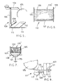
- Fig. 1 shows a perspective view from the side of an effluent irrigator according to the invention
- Fig. 2 shows a side elevation of a drive mechanism for the irrigator shown in Fig. 1;
- Fig. 3 shows a plan view of the drive mechanism shown in Fig. 2;
- Fig. 4 shows a perspective view of part of a second embodiment.
- Fig. 5 is a schematic view in perspective of a device to ensure disengagement of drive at the end of a run
- Fig. 6 is a schematic elevational view of a drum and wire guide according to the invention.
- Fig. 7 is a schematic plan view, to a smaller scale than Fig. 6, of the drum and wire guide of that figure;
- Figure 8 is a schematic side elevational view of a back stop device.
- the irrigator has a rotatable boom 1 at the ends of which are angled regions 2.
- the angled regions 2 are directed on opposite sides of the longitudinal axis of the boom 1 to cause rotation therein when water is pumped to the boom 1.
- the regions 2 may have rubber or the like nozzles 3 chosen so that larger pieces of effluent can be pumped therefrom.
- the boom 1 may be two lengths of galvanised or PVC 50mm pipe joined at the centre by a T-junction 4.
- the boom 1 is supported by an upper part 5 of an upstand 6.
- the upper part 5 can rotate relative to the wheeled frame 7 on which it is supported.
- the part 5 has on the periphery thereof at least one cam surface 8. In the example a single cam is shown. If varying travelling speeds are required then two cams on opposite sides of the part 5 can be included to increase the number of times the cam means operates per revolution of the boom 1 or the teeth on the ratchet wheel can be changed to adjust the speed of revolution of the boom.
- the bottom of the upstand 6 (which is hollow or has a passage therethrough) is connected to a water connection 9 at the rear of the wheeled frame 7.
- the wheeled frame 7 may be generally T- or V-shaped with a transverse member 10 supporting at its ends a pair of wheels 11.
- the longitudinal arms 12 of the frame 7 may support a front wheel (not shown) or a skid 13 as shown.
- the forward end 14 may support a tube 15 through which a cable 16 passes.
- One end of the cable 16 is fixed to a winch drum 17 mounted on the frame 7 while the other end is fixed to a post or spike driven into the ground at the end of the area over which the effluent is to be dispersed.
- the winch drum 17 is mounted with its axis transversely mounted and horizontal as shown.
- one end flange 18 is a ratchet wheel in contact with the teeth on the periphery of which is a ratchet lever 19.
- the axle 20 supporting the winch drum 17 may include a cranked handle 21 for manual winding in of the cable 16.
- the ratchet lever 19 is supported by a connecting rod 22 which moves arcuately.
- the connecting rod 22 or the end of the ratchet lever 19 has a wheel 23 which runs on the cam surface 8.
- the lower end 24 of the rod 22 has a biasing means 25 attached thereto.
- the biasing means 25 is adapted to hold the wheel 23 in contact with the cam surface 8 and the surface of the upper part 5.
- the effluent irrigator 100 is similar to that shown in Figs. 1-3, except that the cam 101 is a double cam, and there is a means in the form of an adjustable stop 102 which determines whether connecting rod 103 allows the ratchet 104 to be retracted a greater or lesser extent, and so determines the speed of the irrigator 100 over the ground.
- the stop 102 comprises a rod mounted in a tube into which it can be retracted and from which it can be extended, as by being screwed when they are screw-threaded.
- the rod has a head 102' against which rod 103 abuts.
- Adjustment of the rod may be so that the ratchet 104 is retracted 4 teeth of the wheel 105, for fast travel, or say one (1) tooth of the wheel 105 for slow travel.
- the adjusting means 102 suitably provides four different forward speeds, and the clearance between the two parts of the cam 101 is half the spacing between the teeth of wheel 105 so as to provide a non-jamming arrangement on rotation.
- the irrigator 100 has a frame similar to that shown in Figs. 1-3, and includes extending tranversely thereof and forwardly, in use, of the upstand 107, a journal in the form of a rod 108 which extends right across the frame for mounting and providing a common axis of rotation for a device 109 to ensure disengagement of the drive at the end of a run, a wire guide 110, and a back stop device 111.
- the device 109 comprises a counterbalance weight in the form of a plate 112 mounted on the lower (in use) end of rod 103 on the side of the rod or journal 108 remote from ratchet 104 by a support 113.
- a spring 114 equivalent to the spring 25 of the first embodiment is connected to the plate 112.
- the plate 112 acts at the end of a run to disengage the drive by pivoting the support 113 clockwise (as viewed in Fig. 5) when the tension of spring 114 is released, so ensuring that the rod 103 and hence ratchet 104 also pivot about rod or journal 108 out of the range of the cam 101 for total disengagement.
- the ratchet 104 slides forwardly over the teeth of wheel 105 but out of driving engagement with them.
- the back stop device 111 (Fig.8) is used at the start of an irrigation run to ensure that the driving gear, that is wheel 105 and ratchet 104 are properly engaged.
- the device 111 comprises a toggle lever 115 journalled for rotation on the rod or journal 108.
- One arm 116 of the lever 115 comprises a ratchet or pawl and the other 117, a weight.
- a pull rod 118 is pivoted to the pawl 116 and has a stop 120 which can be received in a slat or stirrup 121 on the upstand 107.
- a spring 122 is connected between the lever 115 and the upstand 107 and normally acts to urge the pawl 116 into engagement with wheel 105. In use the pull rod 118 is released normally by lifting from the seat 121, or stirrup to release stop 120 so that the spring 122 urges the pawl 116 into engagement with the teeth of the wheel 105.
- the wire guide 110 comprises a round section bar 123 (Fig. 6) held by a frame 124 pivotally mounted on the rod or journal 108 under adjustable spring pressure 135 , the end of the spring 135 remote from the bar 123 being secured by a threaded rod and nut arrangement in a part of the frame of the irrigator to provide the adjustment.
- the bar 123 is situated between the side flanges 105, of the drum 105', and is spaced from each flange 105,125 by a distance less than the diameter of the wire or cable 16.
- the distance between the curved surface of the rod 123 and the surface of the drum 105' is just sufficient to enable the wire or cable to pass through and be wound onto or unwound from the drum 105'.
- the drum 105' itself has formed in its surface a thread like groove 126 each turn of which is equal to (or just slightly greater in width than) the diameter of the wire or cable 16. In use, like cable 16 is passed between the rod 123 and drum 105' and wound round the drum from one end.
- the bar 123 guides the cable 16 evenly across the drum because it is under a greater tension (from spring 135) than the tension of the wire.
- the wire lays itself in the thread 126 as it traverses the drum 105' when it reaches the end opposite that from which it started, it effectively has nowhere to go except back across the drum in a reverse traverse, the layer of wire already laid down effectively providing the "thread".
- the extra thickness of wire pushes the bar 123 away against the spring 135 pressure so that the rod still acts as a guide. In this way the wire is guided to-and-fro across the drum as the irrigator makes its full traverse of the land being irrigated.
- the wire or cable is thus evenly laid up on the drum and is therefore readily wound and unwound without snagging or kinking, and therefore the irrigator operates smoothly over its run.
- the spring 135 is adjustable to provide for different diameters of wire or cable.
- the cam 101 is contoured as shown in Fig. 4 to give a firm even push, via a curved part 128, to the ratchet 104 and to provide via a flat part 129 a slow release of the ratchet over the first three teeth of wheel 105 in a four teeth driving section before the gap or concave curved part 130 which provides a clean or rapid disengagement of the ratchet as it falls away from the teeth, prior to engagement by the next curved part 128 to start the next drawing action.
- the cam 101 acts on the ratchet and therefore in the fast setting of the adjustable means 102, one revolution of the upstand can move eight teeth.
- a seal of oil impregnated nylon (or similar suitable plastics material) where the boom 106 rotates in the upstand 107, to provide smooth rotation, and which is inert and does not become corroded by the highly corrosive effluent.
- the angle of the nozzle at each end of the boom is in the range 45°-30° (preferably 45°) to the longitudinal axis of the boom.
- a small scale irrigator or liquid waste disposal mechanism operate under low pressure (2 bar:30 psi) of effluent passing through a large diameter (7.5cm) pipe.
- the pawl 104 may not be directly struck by the cam, but may move to and fro in a guide operated by the cam.
Landscapes
- Engineering & Computer Science (AREA)
- Water Supply & Treatment (AREA)
- Life Sciences & Earth Sciences (AREA)
- Environmental Sciences (AREA)
- Catching Or Destruction (AREA)
Claims (12)
- Mécanisme pour disperser un liquide comprenant une flèche (1, 106), un châssis monté sur roues (7), un tambour de treuil (17, 105) avec un axe de rotation, une roue à rochets (18) reliée au tambour (17, 105'), un levier à rochets (19, 104) supporté par une barre de liaison (22, 103), un moyen d'entrainement (8, 101) du tambour (17, 105') supporté par un motnant (6,107), un raccord de tuyau (9), un moyen de dispersion (3), un moyen (107) de réglage de la vitesse du mécanisme sur le sol, le châssis monté sur roues (7) supportant le tambour de treuil (17, 105') et le montant (6, 107), à l'extrémité inférieure (en service) duquel est installé un raccord de tuyau (9) et à l'extrémité supérieure duquel est monté le moyen d'entrainement (8, 101) sur sa périphérie, le montant (6, 107) étant rotatif par rapport au châssis monté sur roues (7), le dessus de la partie supérieure supportant la flèche (1, 106) à l'une ou l'autre extrémité de laquelle est installé le moyen de dispersion (3) qui est orienté pour projeter de l'eau ou un effluent vers l'extérieur sur les côtés opposés de l'axe longitudinal de la flèche (1, 106), de façon qu'en service, de l'eau ou un effluent soit appliquée par un tuyau souple au raccord et s'élève dans le montant (6, 107), circule le long de la flèche (106) et sorte par le moyen de dispersion (3), la flèche (1, 106) étant entrainée en rotation de façon que le moyen d'entrainement (8, 101) fixé au montant, vienne en prise avec le levier à rochets (19, 104) qui à son tour fait tourner la roue à rochets (18), laquelle actionne le tambour de treuil (17, 105') poru tirer un câble (16) en tirant ainsi le châssis monté sur roues (7) le long du câble (16), caractérisé en ce que le tambour de treuil (17, 105') est installé sur le châssis monté sur roues (7) avec son axe de rotation sensiblement horizontal et perpendiculaire à la direction du mouvement du châssis, en ce que le moyen d'entrainement (8, 101) comprend un moyen de came adapté à actionner le levier à rochets (19, 104), en ce qu'il existe un guide (110) pour guider le câble (16) dans sa traversée du tambour (17, 105'), et en ce qu'il existe un dispositif pivotant (102, 112, 113, 114) pour dégager le moyen d'entrainement (8, 101) à la fin d'une opération du mécanisme.
- Mécanisme selon la revendication 1, caractérisé en ce que le châssis monté sur roues (7), vu en plan, a la forme d'un T ou d'un V.
- Mécanisme selon l'une quelconque des revendications précédentes, caractérisé en ce que la flèche (1) est constituée d'un tuyau monté par un raccord en T en haut du montant (6, 107).
- Mécanisme selon l'une quelconque des revendications précédentes, caractérisé en ce que le moyen de dispersion comprend des becs (3) aux extrémités opposées de la flèche (1).
- Mécanisme selon la revendication 4, caractérisé en ce que les becs (3) sont inclinés de 30 à 45°, et de préférence de 45°, par rapport à l'axe longitudinal de la flèche (1).
- Mécanisme selon l'une quelconque des revendications précédentes, caractérisé en ce que le moyen (102) de réglage de la vitesse du mécanisme sur le sol comporte une tige mobile entrant et sortant d'une monture portée par le montant (107) et contre laquelle la tige de liaison (103) vient buter lorsqu'elle n'est pas actionnée par la came.
- Mécanisme selon la revendication 6, caractérisé en ce que le moyen de came (8) comprend deux parties (101) qui agissent tour à tour sur le levier à rochets, l'espacement entre les deux pièces étant d'environ la moitié de la distance entre axes des dents de la roue à rochets.
- Mécanisme selon la revendication 7, caractérisé en ce que les deux parties sont deux plaques montées diamétralement sur une partie du montant (107).
- Mécanisme selon la revendication 8, caractérisé en Ce que chaque plaque (101) comporte une partie courbe (118) et une partie sensiblement plate (129), les parties plates (129) conduisant à une trajectoire concave (130) entre les deux plaques.
- Mécanisme selon l'une des revendications précédentes, caractérisé par le fait que le dispositif pivotant (109) comporte un contre-poids (112).
- Mécanisme selon l'une quelconque des revendications précédentes, caractérisé par un dispositif de butée arrière (111).
- Mécanisme selon l'une quelconque des revendications précédentes, caractérisé par un moyen de guidage du câble (15).
Priority Applications (1)
| Application Number | Priority Date | Filing Date | Title |
|---|---|---|---|
| AT86300020T ATE62101T1 (de) | 1985-01-04 | 1986-01-03 | Fluessigkeitsverteilervorrichtung. |
Applications Claiming Priority (4)
| Application Number | Priority Date | Filing Date | Title |
|---|---|---|---|
| NZ21073985A NZ210739A (en) | 1985-01-04 | 1985-01-04 | Self propelled irrigator:rotating boom drives winch drum to wind in anchored cable |
| NZ210739 | 1985-01-04 | ||
| NZ210791A NZ210791A (en) | 1985-01-04 | 1985-01-09 | Self propelled irrigator:rotating boom drives winch drum to wind in anchored cable |
| NZ210791 | 1985-01-09 |
Publications (3)
| Publication Number | Publication Date |
|---|---|
| EP0188308A2 EP0188308A2 (fr) | 1986-07-23 |
| EP0188308A3 EP0188308A3 (en) | 1986-10-01 |
| EP0188308B1 true EP0188308B1 (fr) | 1991-04-03 |
Family
ID=26650628
Family Applications (1)
| Application Number | Title | Priority Date | Filing Date |
|---|---|---|---|
| EP86300020A Expired - Lifetime EP0188308B1 (fr) | 1985-01-04 | 1986-01-03 | Dispositif de distribution de liquides |
Country Status (7)
| Country | Link |
|---|---|
| EP (1) | EP0188308B1 (fr) |
| AU (1) | AU592544B2 (fr) |
| DE (1) | DE3678454D1 (fr) |
| ES (1) | ES8706367A1 (fr) |
| GB (1) | GB2169481B (fr) |
| NZ (1) | NZ210791A (fr) |
| PT (1) | PT81787B (fr) |
Families Citing this family (4)
| Publication number | Priority date | Publication date | Assignee | Title |
|---|---|---|---|---|
| NZ512271A (en) * | 2001-06-08 | 2003-09-26 | Stuart Dundonald Reid | Travelling irrigator with governor controlling winding speed and depth of liquid application |
| CN108925411A (zh) * | 2018-08-21 | 2018-12-04 | 董炳英 | 一种节约型农用喷灌机 |
| CN108934998A (zh) * | 2018-08-21 | 2018-12-07 | 董炳英 | 一种改进型农用喷灌机 |
| CN118988964B (zh) * | 2024-08-01 | 2025-11-25 | 中国科学院新疆生态与地理研究所 | 一种生态修复用土壤修复剂喷淋设备 |
Family Cites Families (5)
| Publication number | Priority date | Publication date | Assignee | Title |
|---|---|---|---|---|
| GB377418A (en) * | 1930-08-07 | 1932-07-28 | Victor Bonnet | Improvements in or relating to watering apparatus for tennis courts, gardens, or thelike |
| US2078987A (en) * | 1934-08-11 | 1937-05-04 | Lee H Adamson | Traveling sprinkler |
| US2602696A (en) * | 1949-09-14 | 1952-07-08 | David C Salatin | Combined hose reel and lawn sprinkler |
| GB1099321A (en) * | 1964-04-14 | 1968-01-17 | John Derrick Pett | Improvements in or relating to crop sprayers |
| FR2427783A1 (fr) * | 1978-06-09 | 1980-01-04 | Lebrun Henri | Appareil arroseur a rotor |
-
1985
- 1985-01-09 NZ NZ210791A patent/NZ210791A/xx unknown
-
1986
- 1986-01-03 GB GB08600117A patent/GB2169481B/en not_active Expired
- 1986-01-03 PT PT81787A patent/PT81787B/pt not_active IP Right Cessation
- 1986-01-03 ES ES550671A patent/ES8706367A1/es not_active Expired
- 1986-01-03 DE DE8686300020T patent/DE3678454D1/de not_active Expired - Fee Related
- 1986-01-03 EP EP86300020A patent/EP0188308B1/fr not_active Expired - Lifetime
- 1986-01-06 AU AU51864/86A patent/AU592544B2/en not_active Ceased
Also Published As
| Publication number | Publication date |
|---|---|
| EP0188308A2 (fr) | 1986-07-23 |
| PT81787A (en) | 1986-02-01 |
| GB8600117D0 (en) | 1986-02-12 |
| AU5186486A (en) | 1986-07-10 |
| AU592544B2 (en) | 1990-01-18 |
| GB2169481A (en) | 1986-07-16 |
| EP0188308A3 (en) | 1986-10-01 |
| GB2169481B (en) | 1988-12-29 |
| NZ210791A (en) | 1986-09-10 |
| ES8706367A1 (es) | 1987-06-16 |
| DE3678454D1 (de) | 1991-05-08 |
| PT81787B (pt) | 1991-10-31 |
| ES550671A0 (es) | 1987-06-16 |
Similar Documents
| Publication | Publication Date | Title |
|---|---|---|
| CA2157620C (fr) | Arroseur automatique | |
| US3942722A (en) | Ground treatment apparatus | |
| US3684178A (en) | Traveling agricultural sprinkler | |
| US10219429B2 (en) | Method and apparatus for applying liquid nutrients between parallel rows of standing crops | |
| US9247693B2 (en) | Irrigation systems | |
| US1919703A (en) | Apparatus for watering or spraying gardens and the like | |
| EP0188308A2 (fr) | Dispositif de distribution de liquides | |
| US4253619A (en) | Apparatus for handling elongate flexible material | |
| NZ210739A (en) | Self propelled irrigator:rotating boom drives winch drum to wind in anchored cable | |
| US3281081A (en) | Irrigation system | |
| US1714713A (en) | Lawn-sprinkling device | |
| US4283010A (en) | Method and apparatus for irrigation of fields by means of flexible hoses | |
| US4538761A (en) | Windup-hose irrigating apparatus | |
| US3446235A (en) | Hose-handling apparatus,self-propelled,with horizontal drum | |
| CA1255915A (fr) | Cable a fibre optique | |
| US5236131A (en) | Vehicle for distributing liquid over the ground | |
| DE2813515A1 (de) | Selektiv ueber einen teilkreis oder einen vollkreis drehbarer rieslerkopf | |
| US4632494A (en) | Linear moving irrigating apparatus | |
| US4664316A (en) | Steerable irrigation system | |
| US4501392A (en) | Torque driven irrigation system | |
| JPH0418369Y2 (fr) | ||
| AU9735401A (en) | Improvements to travelling irrigations for water and effluent applications | |
| CA3012528C (fr) | Methode et appareil d'application de nutriments liquides entre les rangees paralleles de cultures sur pied | |
| FR2634969A1 (fr) | Procede pour l'arrosage de grandes surfaces et dispositif pour la mise en oeuvre de ce procede | |
| US4674685A (en) | Spraying system |
Legal Events
| Date | Code | Title | Description |
|---|---|---|---|
| PUAI | Public reference made under article 153(3) epc to a published international application that has entered the european phase |
Free format text: ORIGINAL CODE: 0009012 |
|
| AK | Designated contracting states |
Kind code of ref document: A2 Designated state(s): AT BE CH DE FR GB IT LI LU NL SE |
|
| PUAL | Search report despatched |
Free format text: ORIGINAL CODE: 0009013 |
|
| AK | Designated contracting states |
Kind code of ref document: A3 Designated state(s): AT BE CH DE FR GB IT LI LU NL SE |
|
| 17P | Request for examination filed |
Effective date: 19870331 |
|
| 17Q | First examination report despatched |
Effective date: 19881010 |
|
| ITCL | It: translation for ep claims filed |
Representative=s name: STUDIO ING. ALFREDO RAIMONDI |
|
| RAP3 | Party data changed (applicant data changed or rights of an application transferred) |
Owner name: BRIGGS IRRIGATION UK LIMITED |
|
| GRAA | (expected) grant |
Free format text: ORIGINAL CODE: 0009210 |
|
| AK | Designated contracting states |
Kind code of ref document: B1 Designated state(s): AT BE CH DE FR GB IT LI LU NL SE |
|
| PG25 | Lapsed in a contracting state [announced via postgrant information from national office to epo] |
Ref country code: SE Effective date: 19910403 |
|
| REF | Corresponds to: |
Ref document number: 62101 Country of ref document: AT Date of ref document: 19910415 Kind code of ref document: T |
|
| ET | Fr: translation filed | ||
| REF | Corresponds to: |
Ref document number: 3678454 Country of ref document: DE Date of ref document: 19910508 |
|
| ITF | It: translation for a ep patent filed | ||
| PG25 | Lapsed in a contracting state [announced via postgrant information from national office to epo] |
Ref country code: LU Free format text: LAPSE BECAUSE OF NON-PAYMENT OF DUE FEES Effective date: 19920131 |
|
| PLBE | No opposition filed within time limit |
Free format text: ORIGINAL CODE: 0009261 |
|
| STAA | Information on the status of an ep patent application or granted ep patent |
Free format text: STATUS: NO OPPOSITION FILED WITHIN TIME LIMIT |
|
| 26N | No opposition filed | ||
| PGFP | Annual fee paid to national office [announced via postgrant information from national office to epo] |
Ref country code: GB Payment date: 19951227 Year of fee payment: 11 |
|
| PGFP | Annual fee paid to national office [announced via postgrant information from national office to epo] |
Ref country code: FR Payment date: 19960109 Year of fee payment: 11 |
|
| PGFP | Annual fee paid to national office [announced via postgrant information from national office to epo] |
Ref country code: AT Payment date: 19960111 Year of fee payment: 11 |
|
| PGFP | Annual fee paid to national office [announced via postgrant information from national office to epo] |
Ref country code: DE Payment date: 19960115 Year of fee payment: 11 |
|
| PGFP | Annual fee paid to national office [announced via postgrant information from national office to epo] |
Ref country code: CH Payment date: 19960129 Year of fee payment: 11 |
|
| PGFP | Annual fee paid to national office [announced via postgrant information from national office to epo] |
Ref country code: NL Payment date: 19960130 Year of fee payment: 11 |
|
| PGFP | Annual fee paid to national office [announced via postgrant information from national office to epo] |
Ref country code: BE Payment date: 19960212 Year of fee payment: 11 |
|
| PG25 | Lapsed in a contracting state [announced via postgrant information from national office to epo] |
Ref country code: GB Effective date: 19970103 Ref country code: AT Effective date: 19970103 |
|
| PG25 | Lapsed in a contracting state [announced via postgrant information from national office to epo] |
Ref country code: LI Effective date: 19970131 Ref country code: CH Effective date: 19970131 Ref country code: BE Effective date: 19970131 |
|
| BERE | Be: lapsed |
Owner name: BRIGGS IRRIGATION UK LTD Effective date: 19970131 |
|
| PG25 | Lapsed in a contracting state [announced via postgrant information from national office to epo] |
Ref country code: NL Effective date: 19970801 |
|
| GBPC | Gb: european patent ceased through non-payment of renewal fee |
Effective date: 19970103 |
|
| REG | Reference to a national code |
Ref country code: CH Ref legal event code: PL |
|
| PG25 | Lapsed in a contracting state [announced via postgrant information from national office to epo] |
Ref country code: FR Effective date: 19970930 |
|
| NLV4 | Nl: lapsed or anulled due to non-payment of the annual fee |
Effective date: 19970801 |
|
| PG25 | Lapsed in a contracting state [announced via postgrant information from national office to epo] |
Ref country code: DE Effective date: 19971001 |
|
| REG | Reference to a national code |
Ref country code: FR Ref legal event code: ST |
|
| PG25 | Lapsed in a contracting state [announced via postgrant information from national office to epo] |
Ref country code: IT Free format text: LAPSE BECAUSE OF NON-PAYMENT OF DUE FEES;WARNING: LAPSES OF ITALIAN PATENTS WITH EFFECTIVE DATE BEFORE 2007 MAY HAVE OCCURRED AT ANY TIME BEFORE 2007. THE CORRECT EFFECTIVE DATE MAY BE DIFFERENT FROM THE ONE RECORDED. Effective date: 20050103 |