EP0188347A2 - Cable coaxial de fuite et sa méthode de fabrication - Google Patents
Cable coaxial de fuite et sa méthode de fabrication Download PDFInfo
- Publication number
- EP0188347A2 EP0188347A2 EP86300170A EP86300170A EP0188347A2 EP 0188347 A2 EP0188347 A2 EP 0188347A2 EP 86300170 A EP86300170 A EP 86300170A EP 86300170 A EP86300170 A EP 86300170A EP 0188347 A2 EP0188347 A2 EP 0188347A2
- Authority
- EP
- European Patent Office
- Prior art keywords
- tape
- conductive
- leaky coaxial
- coaxial cable
- layer
- Prior art date
- Legal status (The legal status is an assumption and is not a legal conclusion. Google has not performed a legal analysis and makes no representation as to the accuracy of the status listed.)
- Granted
Links
Images

Classifications
-
- H—ELECTRICITY
- H01—ELECTRIC ELEMENTS
- H01P—WAVEGUIDES; RESONATORS, LINES, OR OTHER DEVICES OF THE WAVEGUIDE TYPE
- H01P11/00—Apparatus or processes specially adapted for manufacturing waveguides or resonators, lines, or other devices of the waveguide type
- H01P11/001—Manufacturing waveguides or transmission lines of the waveguide type
- H01P11/005—Manufacturing coaxial lines
-
- H—ELECTRICITY
- H01—ELECTRIC ELEMENTS
- H01Q—ANTENNAS, i.e. RADIO AERIALS
- H01Q13/00—Waveguide horns or mouths; Slot antennas; Leaky-waveguide antennas; Equivalent structures causing radiation along the transmission path of a guided wave
- H01Q13/20—Non-resonant leaky-waveguide or transmission-line antennas; Equivalent structures causing radiation along the transmission path of a guided wave
- H01Q13/203—Leaky coaxial lines
Definitions
- This invention relates to a leaky coaxial cable, such as is used for guided communications, obstacle detection, and perimeter security and to a method of making such a cable.
- the present invention relates to a leaky coaxial cable of the type having a central conductor, a dielectric layer therearound and an outer conducting shield.
- Leaky coaxial cables sometimes known as ported coaxial cables or radiating coaxial cables, are generally constructed with gaps or apertures in their outer shield which permit a portion of the internal field to couple to the external environment and external fields to couple to the cable.
- US-A-4 300 338 discloses a design with rhombic shaped apertures in the outer conductor. Both inductive and capacitive coupling is produced having a magnitude dependent on the size, shape, orientation and density of the apertures.
- Leaky coaxial cables can also be produced with thin, solid, tubular outer shields, as described in US-A-3 681 717, in which there is diffusion coupling through the shield due to its thickness being of the same order as, or smaller than, the skin depth at the frequency of operation. Finally, it is known that by use of a spiral or solenoidal construction path along the outer conductor inductive coupling can be produced with no aperture of gap necessarily being present.
- US-A-3 735 293 describes a cable having an outer conductor formed from closely wound metal tape with an insulating backing.
- Diffusion coupling cables such as are described in US-A-3 681 717, are limited in leaky cable applications both because the resulting coupling is weak and a substantial increase in attenuation results from the requirement that the thickness of the outer shield must be reduced.
- induction cables Cables relying on a solenoidal conductive path in the outer conductor, such as are described in U S -A-3 736 293, called induction cables, have been restricted to use at low frequencies, because the resulting large inductive coupling increases linearly with frequency. This has been found to cause large mismatch effects and high coaxial attenuation due to a high degree of coupling when used in the frequency range of typical applications, greater than 30 MHz. Frequencies in the 30-200 MHz band are used for the detection of humans or obstacles which have a dimension of approximately 1/4 wavelength in this band. Also coaxial attenuation is inherently high for cables using high pitch angle conductors to produce the solenoidal currents since the conductor path is long.
- Typical application angles for spiral tapes in normal manufacturing practice is in the range 30-70 degrees (e.g. see US-A-3 735 293, 3 949 329 and 3 870 977).
- Coaxial attenuation increases approximately as the inverse of the cosine squared of the pitch angle for full coverage spiral tapes.
- the outer shield comprises conductive tape arranged in spiral configuration with adjacent edges closely spaced and insulated from one another, the pitch angle of the tape with respect to the longitudinal axis of the cable being less than 30°.
- the term 'closely spaced' is intended to encompass a range of configurations in which successive turns can overlap and in which the edges of successive turns can lie side-by-side with a small spacing between them.
- the invention also provides a method of making a leaky coaxial cable having an acceptable level of inductive coupling, low capacitive coupling and low attenuation by:
- the conductor is typically bonded both to the dielectric layer, and to itself, providing mechanical stability during production and flexing in use.
- the bonding also serves to provide protection of the underlying dielectric from moisture ingress from the environment.
- the full surface coverage of the dielectric by the outer conductor results in almost no capacitive coupling, and hence negligible losses and adverse interaction effects due to this factor.
- conductive tape it is intended to include also served or braided wires which function in the same manner.
- FIG. 1 shows the construction of a leaky coaxial cable in accordance with the invention.
- a centre conductor 1 has a concentric dielectric layer 2 formed thereabout.
- the centre conductor is typically but not necessarily copper, copper-clad aluminum, copper-clad steel, or aluminum.
- the insulating dielectric layer is typically a solid, foamed or air-spaced plastic compound such as polyethylene, polypropylene, or teflon.
- a laminated tape 3 is spirally wound about the dielectric layer.
- the tape 3 has layers, from the inside to the outside of adhesive 5, a non-conductive plastic such as mylar, polyester or polypropylene 6, bonded to a conductor 7 such as copper or aluminum.
- the insulating plastic is not a necessary element if the adhesive itself provides an insulating layer and the conductor is of adequate thickness for mechanical strength.
- edges of adjacent turns to be in close proximity to one another, located between the limits of being slightly gapped and have a slight overlap. In any case there is no conducting path short circuiting the turn.
- the conductive tape thickness can be selected to be several multiples of the skin depth at the frequency of operation to minimize attenuation.
- the tape layer 3 may be covered with an insulating dielectric jacket 4 to provide mechanical protection. It will be clear that the relative location of the adhesive is not critical to the invention. It could be applied to the dielectric layer or on the outside of the tape at least on the portions which overlap. An additional dielectric flooding compound can be introduced between the tape layer and jacket to provide moisture protection and, again as an option, the adhesive layer or additional adhesive layers can be formed between the tape and the jacket.
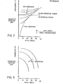
- FIG. 2 shows the inductive coupling as a function of the outer conductor tape width and pitch angle.
- High coupling is produced with a narrow (W/C «1) tape or wire wound at high pitch angle. From experience with leaky cables it has been found that cables constructed with parameters in the upper region of the plot exhibit extremely high coupling, producing strong interaction with the environment and unacceptable changes in coaxial properties such as impedance and attenuation. Cables that are constructed in accordance with the present invention require very wide tapes and very low pitch angles as indicated by the operating region of the plot.
- Figure 3 shows the related capacitive coupling as a function of tape width and pitch angle.
- High capacitive coupling is also produced with a narrow ( W/C «1) tape or served wires.
- capacitive coupling decreases as the pitch angle, and hence physical coverage of the tape, increases.
- the curve indicates that the maximum available full coverage tape pitch angle be used, as the curve asymptotically approaches zero at this angle.
- the adhesive layer 5 is used primarily to ensure tapes of such extremely high width and low pitch angle can be retained in the prescribed position. It also serves as a protective barrier to prevent moisture ingress to the dielectric.
- An alternative construction of the leaky cable is shown in Figure 4.
- the outer conductor from the inside out, consists of a metallic drain wire conductor 10 in contact with a laminated tape consisting of a metallic conductive layer 11 in contact with the drain wire, and an insulating layer 6 providing insulation between turns.
- the drain wire and laminated tape are wound at pitch angles selected in accordance with the above range.
- an insulating tape 9 is wound at a relatively higher pitch than the laminated tape.
- This tape 9 can be wound either with the same or opposite lay as the laminated tape.
- the drain wire performs its conventional function of ensuring that the surface formed by the tape is at a uniform electrostatic potential. It will be clear that the order of the conducting layer and insulating layer can be reversed and the cable will function in the same manner.
- Similar constructions using the present invention include the use of commercially available laminate tapes having several conductive and insulating layers of same or different widths or the use of more than one parallel spiral conductive tape or served wires. The latter could be used, for example, to improve mechanical characteristics such as flexibility. The same low pitch angle and coverage are required.
- Grading or modulation of the leaky cable can also be achieved by ensuring that the inductive coupling is modified with distance along the cable relative to the incremental coaxial attenuation at the frequency of operation.
- coupling can be increased by moving up the full coverage line from a low to higher pitch angle and decreasing tape width.
- Figure 5 shows the outer conductive tape at two different sections along a radiating cable constructed to provide for constant sensitivity along the cable length. The information of Figures 2 and 3, as well as information relating to attenuation at the frequency of operation is used to derive the precise variation of tape width and pitch angle with distance along the cable.
Landscapes
- Engineering & Computer Science (AREA)
- Manufacturing & Machinery (AREA)
- Waveguide Aerials (AREA)
Applications Claiming Priority (2)
| Application Number | Priority Date | Filing Date | Title |
|---|---|---|---|
| CA472030 | 1985-01-14 | ||
| CA000472030A CA1228900A (fr) | 1985-01-14 | 1985-01-14 | Cable coaxial fuyant |
Publications (3)
| Publication Number | Publication Date |
|---|---|
| EP0188347A2 true EP0188347A2 (fr) | 1986-07-23 |
| EP0188347A3 EP0188347A3 (en) | 1988-07-27 |
| EP0188347B1 EP0188347B1 (fr) | 1991-05-02 |
Family
ID=4129568
Family Applications (1)
| Application Number | Title | Priority Date | Filing Date |
|---|---|---|---|
| EP86300170A Expired EP0188347B1 (fr) | 1985-01-14 | 1986-01-13 | Cable coaxial de fuite et sa méthode de fabrication |
Country Status (4)
| Country | Link |
|---|---|
| US (1) | US4760362A (fr) |
| EP (1) | EP0188347B1 (fr) |
| CA (1) | CA1228900A (fr) |
| DE (1) | DE3678972D1 (fr) |
Cited By (3)
| Publication number | Priority date | Publication date | Assignee | Title |
|---|---|---|---|---|
| EP0402050A3 (fr) * | 1989-06-05 | 1991-12-11 | Gec-Marconi Limited | Conducteurs centraux pour une ligne triplaque |
| DE4106890A1 (de) * | 1991-03-05 | 1992-09-10 | Rheydt Kabelwerk Ag | Strahlendes hochfrequenzkabel |
| GB2318689A (en) * | 1996-10-24 | 1998-04-29 | Senstar Stellar Corp | Leaky coaxial cable arrangement |
Families Citing this family (12)
| Publication number | Priority date | Publication date | Assignee | Title |
|---|---|---|---|---|
| DE69418536T2 (de) * | 1993-06-21 | 2000-03-02 | Raytheon Co., Lexington | Radarsystem und zugehörige Komponenten zum Senden eines elektromagnetischen Unterwassersignals |
| US6577236B2 (en) | 2000-09-05 | 2003-06-10 | Robert Keith Harman | FM CW cable guided intrusion detection radar |
| US9728304B2 (en) | 2009-07-16 | 2017-08-08 | Pct International, Inc. | Shielding tape with multiple foil layers |
| US8395296B2 (en) * | 2009-09-16 | 2013-03-12 | Siemens Energy, Inc. | Tape structure with conductive outer side and electrically insulating inner side |
| US8882520B2 (en) | 2010-05-21 | 2014-11-11 | Pct International, Inc. | Connector with a locking mechanism and a movable collet |
| US8579658B2 (en) | 2010-08-20 | 2013-11-12 | Timothy L. Youtsey | Coaxial cable connectors with washers for preventing separation of mated connectors |
| US9028276B2 (en) | 2011-12-06 | 2015-05-12 | Pct International, Inc. | Coaxial cable continuity device |
| US9330815B2 (en) | 2013-08-14 | 2016-05-03 | Apple Inc. | Cable structures with insulating tape and systems and methods for making the same |
| DE102017101646A1 (de) * | 2017-01-27 | 2018-08-02 | Fatzer Ag Drahtseilfabrik | Längselement, insbesondere für ein Zug- oder Tragmittel |
| RU2707385C1 (ru) * | 2018-07-19 | 2019-11-26 | Федеральное государственное бюджетное образовательное учреждение высшего образования "Поволжский государственный университет телекоммуникаций и информатики" | Способ информационной защиты элемента распределенной случайной антенны |
| US11848120B2 (en) | 2020-06-05 | 2023-12-19 | Pct International, Inc. | Quad-shield cable |
| CN112908551B (zh) * | 2021-01-18 | 2022-08-26 | 成都大唐线缆有限公司 | 一种漏泄同轴电缆 |
Family Cites Families (11)
| Publication number | Priority date | Publication date | Assignee | Title |
|---|---|---|---|---|
| US3927247A (en) * | 1968-10-07 | 1975-12-16 | Belden Corp | Shielded coaxial cable |
| BE758602A (fr) * | 1970-02-24 | 1971-04-16 | Kabel Metallwerke Ghh | Ligne haute frequence |
| DE2022990A1 (de) * | 1970-05-12 | 1971-12-02 | Kabel Metallwerke Ghh | Hochfrequenzleitung |
| GB1399844A (en) * | 1973-02-13 | 1975-07-02 | Coal Industry Patents Ltd | Radiating transmission lines |
| US3870977A (en) * | 1973-09-25 | 1975-03-11 | Times Wire And Cable Companay | Radiating coaxial cable |
| JPS5277622A (en) * | 1975-12-24 | 1977-06-30 | Sumitomo Electric Ind Ltd | Tight coupling communication system |
| US4157518A (en) * | 1977-07-27 | 1979-06-05 | Belden Corporation | Leaky coaxial cable having shield layer with uniform gap |
| CA1079504A (fr) * | 1978-10-13 | 1980-06-17 | Control Data Canada | Methode de fabrication de cable coaxial |
| US4339733A (en) * | 1980-09-05 | 1982-07-13 | Times Fiber Communications, Inc. | Radiating cable |
| US4368613A (en) * | 1980-11-12 | 1983-01-18 | Inscon Cable Inc. | Tape wrapped conductor |
| US4432193A (en) * | 1982-09-20 | 1984-02-21 | 501 Control Data Canada, Ltd. | Method of grading radiating transmission lines |
-
1985
- 1985-01-14 CA CA000472030A patent/CA1228900A/fr not_active Expired
- 1985-11-19 US US06/799,693 patent/US4760362A/en not_active Expired - Lifetime
-
1986
- 1986-01-13 EP EP86300170A patent/EP0188347B1/fr not_active Expired
- 1986-01-13 DE DE8686300170T patent/DE3678972D1/de not_active Expired - Lifetime
Cited By (6)
| Publication number | Priority date | Publication date | Assignee | Title |
|---|---|---|---|---|
| EP0402050A3 (fr) * | 1989-06-05 | 1991-12-11 | Gec-Marconi Limited | Conducteurs centraux pour une ligne triplaque |
| GB2232824B (en) * | 1989-06-05 | 1994-03-02 | Marconi Co Ltd | Triplate waveguide structure |
| DE4106890A1 (de) * | 1991-03-05 | 1992-09-10 | Rheydt Kabelwerk Ag | Strahlendes hochfrequenzkabel |
| GB2318689A (en) * | 1996-10-24 | 1998-04-29 | Senstar Stellar Corp | Leaky coaxial cable arrangement |
| GB2318689B (en) * | 1996-10-24 | 2000-12-27 | Senstar Stellar Corp | Sensor cable |
| DE19746087B4 (de) * | 1996-10-24 | 2012-12-13 | Senstar Corp. | Koaxialkabel |
Also Published As
| Publication number | Publication date |
|---|---|
| US4760362A (en) | 1988-07-26 |
| DE3678972D1 (de) | 1991-06-06 |
| CA1228900A (fr) | 1987-11-03 |
| EP0188347A3 (en) | 1988-07-27 |
| EP0188347B1 (fr) | 1991-05-02 |
Similar Documents
| Publication | Publication Date | Title |
|---|---|---|
| US5247270A (en) | Dual leaky cables | |
| EP0188347B1 (fr) | Cable coaxial de fuite et sa méthode de fabrication | |
| US4376920A (en) | Shielded radio frequency transmission cable | |
| US3439111A (en) | Shielded cable for high frequency use | |
| US4987394A (en) | Leaky cables | |
| US4871883A (en) | Electro-magnetic shielding | |
| US4339733A (en) | Radiating cable | |
| KR960009794Y1 (ko) | 하이브리드 차페 케이블 | |
| EP0300334B1 (fr) | Utilisation d' un câble coaxial | |
| US5057646A (en) | Folded ribbon cable assembly having integral shielding | |
| CA1166711A (fr) | Cables electriques a blindage isolant simple | |
| US4510346A (en) | Shielded cable | |
| US5473336A (en) | Cable for use as a distributed antenna | |
| US6259019B1 (en) | Cable for transmitting data and method of manufacturing it | |
| US4680423A (en) | High performance flat cable | |
| US6563052B2 (en) | Electric installation cable | |
| KR20070114840A (ko) | 불연속 케이블 차폐 시스템 및 방법 | |
| US5164692A (en) | Triplet plated-through double layered transmission line | |
| JPS63146306A (ja) | 電気信号伝送特性を改善した伝送線 | |
| US3735293A (en) | High frequency cable | |
| US6201190B1 (en) | Double foil tape coaxial cable | |
| US8809683B2 (en) | Leaky coaxial cable | |
| US5777535A (en) | Coaxial cable with integrated ground discharge wire | |
| JPH11185542A (ja) | 薄膜磁性体シ−ルド付きケ−ブル | |
| CA1332185C (fr) | Cables a fuite |
Legal Events
| Date | Code | Title | Description |
|---|---|---|---|
| PUAI | Public reference made under article 153(3) epc to a published international application that has entered the european phase |
Free format text: ORIGINAL CODE: 0009012 |
|
| AK | Designated contracting states |
Kind code of ref document: A2 Designated state(s): DE FR GB IT |
|
| PUAL | Search report despatched |
Free format text: ORIGINAL CODE: 0009013 |
|
| AK | Designated contracting states |
Kind code of ref document: A3 Designated state(s): DE FR GB IT |
|
| 17P | Request for examination filed |
Effective date: 19890111 |
|
| 17Q | First examination report despatched |
Effective date: 19890622 |
|
| RAP1 | Party data changed (applicant data changed or rights of an application transferred) |
Owner name: SENSTAR CORPORATION |
|
| GRAA | (expected) grant |
Free format text: ORIGINAL CODE: 0009210 |
|
| AK | Designated contracting states |
Kind code of ref document: B1 Designated state(s): DE FR GB IT |
|
| ITF | It: translation for a ep patent filed | ||
| REF | Corresponds to: |
Ref document number: 3678972 Country of ref document: DE Date of ref document: 19910606 |
|
| ET | Fr: translation filed | ||
| PG25 | Lapsed in a contracting state [announced via postgrant information from national office to epo] |
Ref country code: GB Effective date: 19920113 |
|
| PLBE | No opposition filed within time limit |
Free format text: ORIGINAL CODE: 0009261 |
|
| STAA | Information on the status of an ep patent application or granted ep patent |
Free format text: STATUS: NO OPPOSITION FILED WITHIN TIME LIMIT |
|
| 26N | No opposition filed | ||
| GBPC | Gb: european patent ceased through non-payment of renewal fee | ||
| PGFP | Annual fee paid to national office [announced via postgrant information from national office to epo] |
Ref country code: DE Payment date: 19970117 Year of fee payment: 12 |
|
| PGFP | Annual fee paid to national office [announced via postgrant information from national office to epo] |
Ref country code: FR Payment date: 19970131 Year of fee payment: 12 |
|
| PG25 | Lapsed in a contracting state [announced via postgrant information from national office to epo] |
Ref country code: FR Free format text: THE PATENT HAS BEEN ANNULLED BY A DECISION OF A NATIONAL AUTHORITY Effective date: 19980131 |
|
| PG25 | Lapsed in a contracting state [announced via postgrant information from national office to epo] |
Ref country code: DE Free format text: LAPSE BECAUSE OF NON-PAYMENT OF DUE FEES Effective date: 19981001 |
|
| REG | Reference to a national code |
Ref country code: FR Ref legal event code: ST |
|
| PG25 | Lapsed in a contracting state [announced via postgrant information from national office to epo] |
Ref country code: IT Free format text: LAPSE BECAUSE OF NON-PAYMENT OF DUE FEES;WARNING: LAPSES OF ITALIAN PATENTS WITH EFFECTIVE DATE BEFORE 2007 MAY HAVE OCCURRED AT ANY TIME BEFORE 2007. THE CORRECT EFFECTIVE DATE MAY BE DIFFERENT FROM THE ONE RECORDED. Effective date: 20050113 |