EP0188452B1 - Einrichtung zur herstellung von schnittschablonen - Google Patents
Einrichtung zur herstellung von schnittschablonen Download PDFInfo
- Publication number
- EP0188452B1 EP0188452B1 EP19850902951 EP85902951A EP0188452B1 EP 0188452 B1 EP0188452 B1 EP 0188452B1 EP 19850902951 EP19850902951 EP 19850902951 EP 85902951 A EP85902951 A EP 85902951A EP 0188452 B1 EP0188452 B1 EP 0188452B1
- Authority
- EP
- European Patent Office
- Prior art keywords
- cutting
- cutting table
- roller
- templates
- discharge
- Prior art date
- Legal status (The legal status is an assumption and is not a legal conclusion. Google has not performed a legal analysis and makes no representation as to the accuracy of the status listed.)
- Expired - Lifetime
Links
- 238000005520 cutting process Methods 0.000 title abstract description 89
- 239000000463 material Substances 0.000 abstract description 37
- 239000002699 waste material Substances 0.000 description 14
- 238000004804 winding Methods 0.000 description 8
- 238000000926 separation method Methods 0.000 description 2
- 230000000694 effects Effects 0.000 description 1
- 239000004744 fabric Substances 0.000 description 1
- 239000011888 foil Substances 0.000 description 1
- 230000007774 longterm Effects 0.000 description 1
- 238000004519 manufacturing process Methods 0.000 description 1
- 239000002184 metal Substances 0.000 description 1
- 238000000034 method Methods 0.000 description 1
- 238000003801 milling Methods 0.000 description 1
- 238000002360 preparation method Methods 0.000 description 1
- 230000000284 resting effect Effects 0.000 description 1
- 239000004753 textile Substances 0.000 description 1
- 210000001364 upper extremity Anatomy 0.000 description 1
- 238000011144 upstream manufacturing Methods 0.000 description 1
Images
Classifications
-
- B—PERFORMING OPERATIONS; TRANSPORTING
- B26—HAND CUTTING TOOLS; CUTTING; SEVERING
- B26F—PERFORATING; PUNCHING; CUTTING-OUT; STAMPING-OUT; SEVERING BY MEANS OTHER THAN CUTTING
- B26F1/00—Perforating; Punching; Cutting-out; Stamping-out; Apparatus therefor
- B26F1/38—Cutting-out; Stamping-out
- B26F1/3806—Cutting-out; Stamping-out wherein relative movements of tool head and work during cutting have a component tangential to the work surface
- B26F1/3813—Cutting-out; Stamping-out wherein relative movements of tool head and work during cutting have a component tangential to the work surface wherein the tool head is moved in a plane parallel to the work in a coordinate system fixed with respect to the work
-
- B—PERFORMING OPERATIONS; TRANSPORTING
- B26—HAND CUTTING TOOLS; CUTTING; SEVERING
- B26D—CUTTING; DETAILS COMMON TO MACHINES FOR PERFORATING, PUNCHING, CUTTING-OUT, STAMPING-OUT OR SEVERING
- B26D7/00—Details of apparatus for cutting, cutting-out, stamping-out, punching, perforating, or severing by means other than cutting
- B26D7/01—Means for holding or positioning work
- B26D7/018—Holding the work by suction
Definitions
- the invention relates to a device for producing cutting templates with a cutting table, with a supply roller provided on one end part of the cutting table for a flat sheet-like template material to be guided over the cutting table, with a cutting device located above the cutting table for separating the individual cutting templates from the remaining part of the stencil material, with a device for selectively holding the stencil material by negative pressure on the cutting table and with an air-permeable and web-shaped transport pad for the stencil material which can be displaced on the cutting table and which can be deflected via at least one roller attached to the cutting table.
- FR-A-2 490 136 The invention relates to a device for producing cutting templates with a cutting table, with a supply roller provided on one end part of the cutting table for a flat sheet-like template material to be guided over the cutting table, with a cutting device located above the cutting table for separating the individual cutting templates from the remaining part of the stencil material, with a device for selectively holding the stencil material by negative pressure on the cutting table and with an air-permeable and web-
- an automatically controllable cutting device for a slack flat material which has a conveyor table with an endless conveyor belt in order to transport sections of the slack flat material for cutting on the table.
- a tool slide with a cutting tool is arranged above the supporting surface of the table, with which cuts are cut from the slack flat material located on the supporting surface.
- the endless conveyor belt encloses a vacuum chamber. Due to the vacuum in this vacuum chamber, a vacuum acts in the material, whereby it is held in a compressed form on the wing for cutting.
- the generic device is known from FR-A-2 490 136. It has a cutting table, via which an air-permeable transport pad is guided from a unwinding roll to a deflection roll at the opposite end of the cutting table and is wound onto a winding roll. Devices for generating a vacuum are assigned to the cutting table in such a way that this vacuum can have a suction effect on the sheet-like stencil material via the air-permeable transport pad, which is led from an unwinding roller over the cutting table to a stencil removal table. A cutting device is arranged above the cutting table, with which the templates are cut from the template material which is held on the cutting table by suction from the transport pad.
- the rewinding reel With such a device, if the transport pad is completely unwound from the unwinding reel, the rewinding reel must be used instead of the unwinding reel, which is labor intensive. In addition, the individual templates must be removed by hand and the waste material removed by hand. Despite the computer-controlled cutting of the templates, the known device can thus only be operated with the help of an operator who is constantly present.
- the object underlying the invention is now to design the device of the type mentioned in such a way that it can work fully automatically without manual operation.
- the transport pad is a self-contained material loop that wraps around the support surface of the cutting table and is guided around rollers by a tensioning device, and that the opposite end section of the cutting table is equipped with a roller for winding up the waste of the Stencil material or with a device for processing the waste by cutting or with a press, and that that end section of the cutting table where the cutting templates are obtained has a collecting device for the cutting templates, which is arranged on a slanted plate that slopes away from the trailing edge of the cutting table is formed with a stop on its lower edge.
- the cutting table expediently has a drive device for the transport base which can be driven in accordance with the mode of operation of the cutting device.
- the drive device preferably also serves to drive the waste take-up roller or the preparation device for the waste.
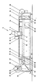
- the device for producing cutting templates which is shown in the accompanying drawing, has a cutting table 1, on which there is the flat material 2 from which cutting templates are made. Above the table 1 there is a device 3 for separating those parts of the flat material 2 from the rest of the same which represent the cutting templates.
- Said separation device 3 contains a bridge 4, which is approximately U-shaped in front view. Through the vertical legs of this bridge 4, of which only the front leg 5 of the bridge 4 can be seen in the drawing, horizontally lying guide rods 6 pass through, which are attached laterally to the cutting table 1 and which run parallel to the working surface of the cutting table 1.
- the web 7 connecting the vertical legs 5 is located above the working surface of the table 1 and extends transversely to the longitudinal direction of the table 1 a cutting device 8 is movable in said web 7.
- This cutting device 8 contains a support part 9, which is in engagement with the bridge 7 and to which a cutting head 10 is attached in a vertically movable manner.
- the section of the cutting head 10 facing the cutting table 1 is provided with a cutting tool 11.
- This cutting tool 11 can be designed, for example, as a milling cutter, graver or knife, or it can act on the template material electroerosively, with an arc, etc.
- the type of cutting tool 11 largely depends on the type of template material 2 used.
- the cutting table 1 is further provided with a control device (not shown) which controls the movements of the bridge 4 on the guide rods 6 along the cutting table 1 and the cutting device 8 along the bridge 4 in accordance with the shape of the desired cutting template. Since such control devices for the production of cutting templates are generally known, a more detailed description of this control device is omitted here.
- the present device also has a transport pad 15 which can be moved along the cutting table 1 and which lies directly on the surface of the cutting table 1 and on which the template material 2 rests in the region of the table surface.
- this transport document 15 is a self-contained, i.e. Endless structure that wraps around the support surface of the cutting table 1.
- the transport pad 15 is shown in the drawing with the aid of a dash-dotted line in order to be able to distinguish this pad 15 in the area of the working surface of the cutting table 1 from the other parts shown here.
- the transport pad can be made of an airtight material, e.g. be made of cardboard, plastic, paper, metal foil, etc., such a transport pad (15) having continuous openings.
- the transport pad can also be made of a textile material, such as from a fabric or from a nonwoven.
- the cutting table 1 is provided with rollers 16, 17, 18 and 19. over which the transport pad 15 is guided. At least one of these rollers 16 to 19 can be driven with the aid of a drive device 20, which is only indicated in the drawing.
- a tensioning device 21 is also provided for the transport pad 15, which has a tensioning roller 22. This tension roller 22 is located above the lower left guide roller 18 for the transport pad 15. The chip roller 22 can be pressed against the outside of the transport pad 15 with the aid of a device (not shown), as a result of which the desired tension in the pad 15 can be achieved.
- the transport pad mentioned is a web which is rewound from one end part of the cutting table 1 to the opposite end part of the same.
- the one end part of the cutting table 1 is provided with a supply roller for the web-shaped transport pad.
- the opposite end of the cutting table is then equipped with a roller for winding up the transport document.
- the rollers just mentioned are driven by the drive device 20 for the transport pad 15.
- the template material 2 already mentioned has the shape of a web in the example shown.
- a supply roll 25 with the stencil material 2 that has not yet been processed Transport pad 15 rests and where it is processed using the cutting device.
- a further roller 26 on which the rest of the template material 2 that has already been processed, i.e. the waste 27 is wound up.
- the winding roller 26 contains a shaft 28, the ends of which each slide in a fork 29 and which can also be driven by means of the drive device 20 already mentioned. Since the take-up roller 26 is merely resting in the forks 29, it can be quickly removed from the device and in its place an empty shaft 28 can simply be inserted into the device.
- Two of the guide rollers 16 and 17 already mentioned for the transport pad 15 are located in the upper region of the cutting table 1 in such a way that the tangent to the respective guide rollers 16 and 17, respectively, which runs horizontally and touches the uppermost part of the guide rollers 16 and 17 mentioned, in the plane of the working surface of the cutting table 1 or a little below.
- Such a position of the upper guide rollers 16 and 17 enables the transport pad 15 to be guided over the working surface of the table 1 without problems.
- the remaining two guide rollers 18 and 19 for the transport pad are located in the lower part of the cutting table 1 and they serve above all to return the Transport pad 15.
- the tensioning roller 22 is connected upstream of the lower left guide roller 18.
- This collecting device 30 contains an obliquely arranged plate 32 falling from the exit edge 31 of the cutting table 1, the lower edge part of this plate 32 being provided with a stop 33.
- This stop 33 is approximately at right angles to the base plate 32 mentioned and it is relatively high so that several layers of cutting templates can rest on this stop 33.
- the entire working surface of the cutting table 1 is provided with transverse air passages 34, of which only two such passages are shown in the drawing.
- the upper The mouth of the respective passage is located under the transport pad 15.
- the passages 34 open into a collecting chamber 35 located under the working surface of the table 1, which is connected via a line 36 to a device 37 for generating negative pressure in the collecting chamber 35 and thus also in the passages 34 is connected.
- the operation of the cutting device 3 is controlled according to the desired shape of the cutting templates. This is done in a known manner using a computer.
- the front end of the web 2 made of the stencil material 2 is guided up to the shaft 28 for the winding roller 26, where this front end of the web 2 is fastened.
- the greater part of the material web 2, which is located between the two rollers 25 and 26, rests on that section of the transport pad 15 which lies on the working surface of the cutting table 1.
- the device 37 for generating negative pressure can now be put into operation, so that air is first extracted from the area below the transport pad 15. Since the base 15 is permeable to air, the air that is located between the stencil material 2 on the table 2 and the transport base is also extracted. The web 2 made of the template material now adheres firmly to the transport base 15 and thus also to the table 1. The cutting templates can now be cut out of the web-shaped material 2.
- the mode of operation of the separating device 3 is programmed in such a way that the separating device 3 can move as far as possible over the entire width and length of the cutting table 1 in order to cut out cutting templates from the template material 2. Here, as little waste as possible 27 should arise.
- the vacuum device 37 is first switched off so that the atmospheric pressure can build up again between the flat material 2 on the table 1 and the table surface.
- the drive device 20 for the transport pad 15 and for the take-up roller 26 for the waste 27 is put into operation.
- the material web 2 and also the transport pad 15 now move in the direction towards the winding roller 26, the waste 27 reaching this roller 26 hanging freely.
- the transport pad 15 is sharply deflected downward, while the waste 27 moves approximately in the same direction to the take-up roller 26.
- the cut-out cutting templates separate from the remaining part of the material web 2 and they fall into the collecting device 30 for the latter.
- the drive device 2 for the transport pad 15 and the winding roller 26 is switched off and the vacuum device 37 can be switched on in order to be able to produce a new set of cutting templates .
- a device for processing the waste 27 by cutting can be provided. This device can also be driven by the device 20 for driving the transport pad 15.
Landscapes
- Life Sciences & Earth Sciences (AREA)
- Forests & Forestry (AREA)
- Engineering & Computer Science (AREA)
- Mechanical Engineering (AREA)
- Details Of Cutting Devices (AREA)
- Control Of Cutting Processes (AREA)
- Treatment Of Fiber Materials (AREA)
Description
- Die Erfindung betrifft eine Einrichtung zur Herstellung von Schnittschablonen mit einem Schneidetisch, mit einem an der einen Endpartie des Schneidetisches vorgesehenen Vorratswalze für ein über den Schneidetisch zu führendes flächenhaftes bahnförmiges Schablonenmaterial, mit einer sich oberhalb des Schneidetisches befindenden Schnittvorrichtung zum Abtrennen der einzelnen Schnittschablonen vom übrigen Teil des Schablonenmaterials, mit einer Vorrichtung zum wahlweisen Festhalten des Schablonenmaterials durch Unterdruck auf dem Schneidetisch und mit einer auf dem Schneidetisch verschiebbaren luftdurchlässigen und bahnförmigen Transportunterlage für das Schablonenmaterial, die über wenigstens eine am Schneidetisch angebrachte Rolle umlenkbar ist. (FR-A-2 490 136).
- Aus der FR-A-2 524 840 ist bereits eine selbsttätig regelbare Schneidevorrichtung für ein schlaffes Flachmaterial bekannt, die einen Fördertisch mit einem endlosen Förderband aufweist, um Abschnitte des schlaffen Flachmaterials zum Schneiden auf den Tisch zu transportiern. Oberhalb der Tragfläche des Tisches ist dabei ein Werkzeugschlitten mit einem Schneidwerkzeug angeordnet, mit welchem Zuschnitte aus dem schlaffen, sich auf der Tragfläche befindenden Flachmaterial geschnitten werden. Mit Ausnahme des Abschnitts des Bandes, der die Tragfläche bildet, umschließt das endlose Förderband eine Unterdruckkammer. Durch das Vakuum in dieser Unterdruckkammer wirkt ein Unterdruck in dem Material, wodurch dieses in zusammengedrückter Form auf der Tragfläche für das Schneiden gehalten wird.
- Die gattungsgemäße Einrichtung ist aus der FR-A-2 490 136 bekannt. Sie weist einen Schneidetisch auf, über den von einer Abwickelrolle eine luftdurchlässige Transportunterlage zu einer Umlenkrolle am gegenüberliegenden Ende des Schneidetisches geführt und auf eine Aufwickelrolle aufgewickelt wird. Dem Schneidetisch sind Einrichtungen zur Erzeugung eines Vakuums derart zugeordnet, daß dieses Vakuum über die luftdurchlässige Transportunterlage saugend an einem bahnförmigen Schablonenmaterial wirken kann, das von einer Abwickelwalze über den Schneidetisch zu einem Schablonenabnahmetisch geführt wird. Über dem Schneidetisch ist eine Schnittvorrichtung angeordnet, mit der die Schablonen aus dem Schablonenmaterial geschnitten werden, das über die Transportunterlage angesaugt am Schneidetisch gehalten ist.
- Wenn bei einer solchen Einrichtung die Transportunterlage vollständig von der Abwickelrolle abgewickelt ist, muß die Aufwickelrolle anstelle der Abwickelrolle eingesetzt werden, was arbeitsaufwendig ist. Außerdem müssen die einzelnen Schablonen von Hand entnommen und das Abfallmaterial von Hand entfernt werden. Die bekannte Einrichtung kann somit trotz des komputergesteuerten Schneidens der Schablonen nur mit Hilfe einer dauernd anwesenden Bedienungsperson betrieben werden.
- Die der Erfindung zugrunde liegende Aufgabe besteht nun darin, die Einrichtung der eingangs genannten Art so auszubilden, daß sie vollautomatisch ohne manuelle Betätigung arbeiten kann.
- Diese Aufgabe wird ausgehend von der Einrichtung der gattungsgemäßen Art dadurch gelöst, daß die Transportunterlage eine in sich geschlossene, die Auflagefläche des Schneidetisches umschlingende und um Rollen über eine Spannvorrichtung geführte Materialbahn ist und daß die gegenüberliegende Endpartie des Schneidetisches mit einer Walze zum Aufwickeln des Abfalls des Schablonenmaterials oder mit einer Vorrichtung zur Aufbereitung des Abfalls durch Zertrennen oder mit einer Presse ausgerüstet ist, und daß jene Endpartie des Schneidetisches, wo die Schnittschablonen anfallen, eine Auffangvorrichtung für die Schnittschablonen aufweist, die von einer schräg angeordneten und von der Austrittskante des Schneidetisches abfallenden Platte mit Anschlag an ihrer unteren Randpartie gebildet wird.
- Mit der erfindungsgemäßen Einrichtung ist es möglich, in einem vollautomatischen Prozeß Schnittschablonen herzustellen, wobei in einem bestimmten Langzeitturnus lediglich das Schnittschablonenmaterial sowohl vom Verbrauch als auch vom Abfall her entfernt und die Schnittschablonen von der Auffangvorrichtung entnommen werden müssen.
- Zweckmäßigerweise weist der Schneidetisch eine in Übereinstimmung mit der Arbeitsweise der Schnittvorrichtung antreibbare Antriebsvorrichtung für die Transportunterlage auf.
- Vorzugsweise dient die Antriebsvorrichtung auch zum Antrieb der Abfallaufwickelwalze bzw. der Aufbereitungsvorrichtung für den Abfall.
- Nachstehend werden Ausführungsbeispiele der vorliegenden Erfindung anhand der beiliegenden Zeichnung näher erläutert. Die einzige Figur der Zeichnung zeigt eine schematische Seitenansicht der vorliegenden Einrichtung.
- Die Einrichtung zur Herstellung von Schnittschablonen, die in der beiliegenden Zeichnung dargestellt ist, weist einen Schneidetisch 1 auf, auf dem sich jenes flachenhafte Material 2 befindet, aus dem Schnittschablonen angefertigt werden. Ueber dem Tisch 1 befindet sich eine Vorrichtung 3 zum Abtrennen jener Partien des flächenhaften Materials 2 vom übrigen Teil desselben, die die Schnittschablonen darstellen.
- Die genannte Trennvorrichtung 3 enthalt eine Brücke 4, die in Frontansicht etwa U-formig ist. Durch die vertikalen Schenkel dieser Brücke 4, von welchen in der Zeichnung nur der vordere Schenkel 5 der Brücke 4 ersichtlich ist, gehen horizontal liegende Führungsstangen 6 hindurch, die seitlich am Schneidetisch 1 angebracht sind und die parallel zur Arbeitsfläche des Schneidetisches 1 verlaufen. Der die vertikalen Schenkel 5 verbindende Steg 7 befindet sich über der Arbeitsfläche des Tisches 1 und er erstreckt sich quer zur Längsrichtung des Tisches 1. Entlang dem genannten Steg 7 ist ein Schneidgerat 8 bewegbar. Dieses Schneidgerät 8 enthält einen Tragteil 9, der mit der Brücke 7 in Eingriff steht und an dem ein Schneidkopf 10 vertikal beweglich angebracht ist. Die dem Schneidetisch 1 zugewandte Partie des Schneidkopfes 10 ist mit einem Schneidwerkzeug 11 versehen. Dieses Schneidwerkzeug 11 kann beispielsweise als ein Fräser, Stichel oder Messer ausgeführt sein, oder es kann auf das Schablonenmaterial elektroerosiv, mit einem Lichtbogen usw. einwirken. Die Art des Schneidwerkzeuges 11 hängt von der Art des verwendeten Schablonenmaterials 2 weitgehend ab.
- Der Schneidetisch 1 ist ferner mit einer Steuervorrichtung (nicht dargestellt) versehen, welche die Bewegungen der Brücke 4 auf den Führungsstangen 6 entlang dem Schneidetisch 1 und des Schneidegerates 8 entlang der Brücke 4 entsprechend der Form der gewünschten Schnittschablone steuert. Da solche Steuervorrichtungen zur Herstellung von Schnittschablonen allgemein bekannt sind, wird hier auf eine nähere Beschreibung dieser Steuervorrichtung verzichtet.
- Die vorliegende Einrichtung weist ferner eine entlang dem Schneidetisch 1 bewegbare Transportunterlage 15 auf, die auf der Oberfläche des Schneidetisches 1 unmittelbar aufliegt und auf der das Schablonenmaterial 2 im Bereich der Tischoberfläche ruht. Im dargestellten Beispiel stellt diese Transportunterlage 15 ein in sich geschlossenes, d.h. endloses Gebilde dar, das die Auflagefläche des Schneidetisches 1 umschlingt. Die Transportunterlage 15 ist in der Zeichnung mit Hilfe einer strichpunktierten Linie dargestellt, um diese Unterlage 15 im Bereich der Arbeitsfläche des Schneidetisches 1 von den übrigen hier dargestellten Teilen unterscheiden zu können. Die Transportunterlage kann aus einem luftdichten Material, wie z.B. aus Karton, Kunststoff, Papier, Metallfolie usw. sein, wobei eine solche Transportunterlage (15) durchgehende Oeffnungen aufweist. Die Transportunterlage kann jedoch auch aus einem textilen Material, wie z.B. aus einem Gewebe oder aus einem Vliesstoff, sein.
- Der Schneidetisch 1 ist mit Rollen 16,17,18 und 19 versehen. über die die Transportunterlage 15 geführt ist. Wenigstens eine dieser Rollen 16 bis 19 ist mit Hilfe einer Antriebsvorrichtung 20 antreibbar, die in der Zeichnung nur angedeutet ist. Es ist ferner eine Spannvorrichtung 21 für die Transportunterlage 15 vorgesehen, die eine Spannwalze 22 aufweist. Diese Spannwalze 22 befindet sich oberhalb der linken unteren Führungsrolle 18 für die Transportunterlage 15. Die Spanwalze 22 kann mit Hilfe einer nicht dargestellten Vorrichtung gegen die Aussenseite der Transportunterlage 15 angedrückt werden, wodurch die gewünschte Spannung in der Unterlage 15 erreicht werden kann.
- Unter Umständen könnte es auch zweckmässig sein, die genannte Transportunterlage als eine Bahn auszuführen, die von einer Endpartie des Schneidetisches 1 zur gegenuberliegenden Endpartie desselben umgespult wird. Hierzu ist die eine Endpartie des Schneidetisches 1 mit einer Vorratswalze für die bahnförmige Transportunterlage versehen. Die gegenüberliegende Endpartie des Schneidetisches ist dann mit einer Walze zur Aufwicklung der Transportunterlage ausgerüstet. Die gerade genannten Walzen werden durch die Antriebsvorrichtung 20 für die Transportunterlage 15 angetrieben.
- Das bereits erwähnte Schablonenmaterial 2 hat im dargestellten Beispiel die Form einer Bahn. An einem Ende des Schneidetisches 1, im dargestellten Beispiel ist dies die rechte Endpartie desselben, befindet sich eine Vorratsrolle 25 mit dem noch nicht verarbeiteten Schablonenmaterial 2. Von dieser Vorratswalze 25 wird das Schablonenmaterial 2 zunächst zur Oberfläche des Schneidetisches 1 geführt, wo es auf der Transportunterlage 15 ruht und wo es mit Hilfe der Schneidvorrichtung bearbeitet wird. Am gegenüberliegend en Ende des Schneidetisches 1 befindet sich eine weitere Walze 26, auf der der Rest des bereits verarbeiteten Schablonenmaterials 2, d.h. der Abfall 27, aufgewickelt ist. Die Aufwickelwalze 26 enthält eine Welle 28, deren Enden in je einer Gabel 29 gleitbar ruhen und die mit Hilfe der bereits genannten Antriebsvorrichtung 20 ebenfalls antreibbar ist. Da die Aufwickelwalze 26 in den Gabeln 29 bloss ruht, kann sie der Einrichtung schnell entnommen werden und an deren Stelle kann man eine noch leere Welle 28 in die Einrichtung bloss einlegen.
- Zwei der bereits erwähnten Führungsrollen 16 und 17 für die Transportunterlage 15 befinden sich im oberen Bereich des Schneidetisches 1 derart, dass die Tangente zur jeweiligen der genannten Führungsrollen 16 bzw. 17, die horizontal verläuft und die oberste Partie der genannten Führungsrollen 16 und 17 berührt, in der Ebene der Arbeitsfläche des Schneidetisches 1 oder ein wenig darunter liegt. Eine solche Lage der oberen Führungsrollen 16 und 17 ermöglicht eine problemlose Führung der Transportunterlage 15 über die Arbeitsfläche des Tisches 1. Die übrigen zwei Führungsrollen 18 und 19 für die Transportunterlage befinden sich in der unteren Partie des Schneidetisches 1 und sie dienen vor allem zur Rückführung der Transportunterlage 15. Die Spannrolle 22 ist der linken unteren Führungsrolle 18 vorgeschaltet.
- Unter der Aufwickelwalze 26 für den Abfall befindet sich eine Auffangvorrichtung 30 für die fertigen Schnittschablonen. Diese Auffangvorrichtung 30 enthält eine schräg angeordnete und von der Austrittskante 31 des Schneidetisches 1 abfallende Platte 32, wobei die untere Randpartie dieser Platte 32 mit einem Anschlag 33 versehen ist. Dieser Anschlag 33 steht etwa rechtwinklig zur genannten Unterlagsplatte 32 und er ist verhältnismässig hoch ausgeführt, damit mehrere Schichten von Schnittschablonen auf diesem Anschlag 33 aufliegen können.
- Die gesamte Arbeitsfläche des Schneidetisches 1 ist mit quer verlaufenden Luftdurchlassen 34 versehen, von welchen in der Zeichnung nur zwei solche Durchlässe dargestellt sind. Die obere Mündung des jeweiligen Durchlasses befindet sich unter der Transportunterlage 15. Andernends münden die Durchlässe 34 in eine sich unter der Arbeitsfläche des Tisches 1 befindliche Sammelkammer 35, die über eine Leitung 36 an eine Vorrichtung 37 zur Erzeugung von Unterdruck in der Sammelkammer 35 und somit auch in den Durchlässen 34 angeschlossen ist.
- Wie erwähnt worden ist, ist die Arbeitsweise der Schneidvorrichtung 3 entsprechend der gewünschten Form der Schnittschablonen gesteuert. Dies geschiet in bekannter Weise mit Hilfe eines Computers. Um den Schneidvorgang durchführen zu können, wird das vordere Ende der Bahn 2 aus dem Schablonenmaterial 2 bis zur Welle 28 für die Aufwickelwalze 26 geführt, wo dieses vordere Ende der Bahn 2 befestigt wird. Der grössere Teil der Materialbahn 2, die sich zwischen den zwei Walzen 25 und 26 befindet, ruht auf jenem Abschnitt der Transportunterlage 15, der auf der Arbeitsfläche des Schneidetisches 1 aufliegt.
- Die Vorrichtung 37 zur Erzeugung von Unterdruck kann jetzt in Betrieb gesetzt werden, so dass Luft zunächst aus dem Bereich unterhalb der Transportunterlage 15 abgesaugt wird. Da die Unterlage 15 luftdurchlässig ist, wird auch jene Luft abgesaugt, die sich zwischen dem Schablonenmaterial 2 auf dem Tisch 2 und der Transportunterlage befindet. Die Bahn 2 aus dem Schablonenmaterial haftet jetzt fest auf der Transportunterlage 15 und somit auch auf dem Tisch 1. Das Ausschneiden der Schnittschablonen aus dem bahnförmigen Material 2 kann jetzt beginnen. Die Arbeitsweise der Trennvorrichtung 3 ist so programmiert, dass sich die Trennvorrichtung 3 möglichst über die gesamte Breite und Länge des Schneidetisches 1 bewegen kann, um Schnittschablonen aus dem Schablonenmaterial 2 auszuschneiden. Hierbei soll möglichst wenig Abfall 27 enstehen.
- Nach dem Abschluss dieses Trennvorganges wird zunächst die Unterdruckvorrichtung 37 abgestellt, damit sich zwischen dem flächenhaften Material 2 auf dem Tisch 1 und der Tischoberfläche der atmospherisch Druck wieder aufbauen kann.
- Dann wird die Antriebsvorrichtung 20 für die Transportunterlage 15 und für die Aufwickelwalze 26 für den Abfall 27 in 8etrieb gesetzt. Die Materialbahn 2 und auch die Transportunterlage 15 bewegen sich jetzt in Richtung gegen die Aufwikkelwalze 26 hin, wobei der Abfall 27 auf diese Walze 26 freihängend gelangt. Im Bereich der linken oberen Führungsrolle 17 wird die Transportunterlage 15 scharf nach unten abgelenkt, während der Abfall 27 sich etwa in derselben Richtung bis zur Aufwickelwalze 26 bewegt. In diesem Bereich der vorliegenden Einrichtung trennen sich die herausgeschnittenen Schnittschablonen vom übrigen Teil der Materialbahn 2 und sie fallen in die Auffangvorrichtung 30 für diese.
- Nachdem die Oberfläche des Schneidetisches 1 mit einem noch nicht behandelten Abschnitt der Materialbahn 2 wieder überdeckt worden ist, wird die Antriebsvorrichtung 2 für die Transportunterlage 15 und die Aufwickelwalze 26 ausgeschaltet und die Unterdruckvorrichtung 37 kann eingeschaltet werden, um einen neuen Satz von Schnittschablonen herstellen zu können.
- Anstelle der Abfallaufwickelwalze 26 kann eine Vorrichtung zur Aufbereitung des Abfalles 27 durch Zertrennen vorgesehen sein. Diese Vorrichtung kann durch die Vorrichtung 20 zum Antrieb der Transportunterlage 15 ebenfalls angetrieben werden.
Claims (3)
Priority Applications (1)
| Application Number | Priority Date | Filing Date | Title |
|---|---|---|---|
| AT85902951T ATE53327T1 (de) | 1984-07-04 | 1985-07-01 | Einrichtung zur herstellung von schnittschablonen. |
Applications Claiming Priority (2)
| Application Number | Priority Date | Filing Date | Title |
|---|---|---|---|
| CH320884 | 1984-07-04 | ||
| CH3208/84 | 1984-07-04 |
Publications (2)
| Publication Number | Publication Date |
|---|---|
| EP0188452A1 EP0188452A1 (de) | 1986-07-30 |
| EP0188452B1 true EP0188452B1 (de) | 1990-06-06 |
Family
ID=4250998
Family Applications (1)
| Application Number | Title | Priority Date | Filing Date |
|---|---|---|---|
| EP19850902951 Expired - Lifetime EP0188452B1 (de) | 1984-07-04 | 1985-07-01 | Einrichtung zur herstellung von schnittschablonen |
Country Status (3)
| Country | Link |
|---|---|
| EP (1) | EP0188452B1 (de) |
| DE (1) | DE3578049D1 (de) |
| WO (1) | WO1986000559A1 (de) |
Families Citing this family (4)
| Publication number | Priority date | Publication date | Assignee | Title |
|---|---|---|---|---|
| EP0361376A3 (de) * | 1988-09-30 | 1991-09-11 | The Boeing Company | Automatisierte Schneid- und Verteilanlage für Verbundwerkstoff und Verfahren |
| EP0387371B1 (de) * | 1989-03-14 | 1994-07-27 | Wolf Dieter Merz | Verfahren und Vorrichtung zum Zuschneiden von Schnitteilen für Bekleidungsstücke |
| CN102990715A (zh) * | 2012-10-29 | 2013-03-27 | 茅惠杰 | 一次性心电电极片裁切机构 |
| DE102019107586B4 (de) * | 2019-03-25 | 2023-03-30 | Held Systems Gmbh | Abnahmevorrichtung zum automatisierten Abnehmen von Gewebematerialteilen, ein Verfahren zum automatisierten Abnehmen von Gewebematerialteilen und eine Produktionsanlage mit einer Fördereinrichtung und einer Abnahmevorrichtung |
Family Cites Families (4)
| Publication number | Priority date | Publication date | Assignee | Title |
|---|---|---|---|---|
| USRE21718E (en) * | 1941-02-18 | Take-off mechanism | ||
| US3592091A (en) * | 1970-06-15 | 1971-07-13 | Allamatic Corp | Diecutter |
| DE3034621A1 (de) * | 1980-09-13 | 1982-05-06 | Aristo Graphic Systeme Gmbh & Co Kg, 2000 Hamburg | Verfahren und schneidvorrichtung zur herstellung von zuschnitten |
| US4476756A (en) * | 1982-04-12 | 1984-10-16 | Gerber Garment Technology, Inc. | Apparatus for working limp sheet material on a conveyor |
-
1985
- 1985-07-01 EP EP19850902951 patent/EP0188452B1/de not_active Expired - Lifetime
- 1985-07-01 DE DE8585902951T patent/DE3578049D1/de not_active Expired - Lifetime
- 1985-07-01 WO PCT/CH1985/000104 patent/WO1986000559A1/de not_active Ceased
Also Published As
| Publication number | Publication date |
|---|---|
| WO1986000559A1 (fr) | 1986-01-30 |
| EP0188452A1 (de) | 1986-07-30 |
| DE3578049D1 (de) | 1990-07-12 |
Similar Documents
| Publication | Publication Date | Title |
|---|---|---|
| DE69016067T2 (de) | Verfahren und Vorrichtung zum Bilden eines neuen Stapels nach dem Abnehmen von einem fertigen Stapel, in einer, insbesondere einem Printer zugeordneten, Stapelbildungsmaschine. | |
| DE69517065T2 (de) | Vorrichtung und Verfahren zum Zuführen von Gewebeabdeckfolie zu einer Schneidemaschine | |
| DE3525040C2 (de) | Einrichtung zur Umlenkung der Förderrichtung von Papierblättern | |
| EP1245729B1 (de) | Vorrichtung zum Überführen einer Bahn | |
| DE3034621A1 (de) | Verfahren und schneidvorrichtung zur herstellung von zuschnitten | |
| WO2002022368A1 (de) | Tintenstrahl-druckvorrichtung | |
| EP0288814B1 (de) | Vorrichtung zum Unterteilen einer endlosen Papierbahn mit Zickzackfalzung | |
| EP0347573B1 (de) | Vefahren und Vorrichtung zum Heranführen des Anfanges einer Materialbahn, insbesondere einer Papierbahn, von unten an eine Rollmaschinenwalze | |
| EP0253165B1 (de) | Bogenanleger | |
| EP2246160A1 (de) | Vorrichtung und Verfahren zum Schneiden von bahn- oder bogenförmigem, für Luft durchlässigem Gewebe- oder Vliesmaterial | |
| CH680363A5 (de) | ||
| DE3117094A1 (de) | Bahneinfuehrungsvorrichtung an wickelmaschinen | |
| DE69817310T2 (de) | Vorrichtung und Verfahren zum Vereinzeln von Bögen von einem Bogenstapel | |
| DE4203520C2 (de) | Zwischenlage-Apparat zur Einbringung von folienartigem Material in die von einer Schneidemaschine geschnittenen Scheiben | |
| DE102007049426A1 (de) | Wellpappe-Streifen-Wende-Vorrichtung | |
| EP0890538B1 (de) | Rollenschneider | |
| DE3324495A1 (de) | Stapelvorrichtung fuer zuschnitte | |
| DE3730923A1 (de) | Aggregat zum zuschneiden und zusammensetzen von streifenmaterial | |
| WO1986000559A1 (fr) | Dispositif pour la fabrication de gabarits de decoupage | |
| DE3933861A1 (de) | Verfahren und vorrichtung zum einfuehren einer materialbahn in eine verarbeitungsmaschine | |
| EP1972718A2 (de) | Vorrichtung zum Führen bzw. Überführen einer Papier-, Karton- oder anderen Faserstoffbahn | |
| DD148756A1 (de) | Vorrichtung zur bildung einer folge von sich unterlappenden bogen | |
| DE10248107B4 (de) | Vorrichtung zum Zuschneiden von bahnförmigen Textilmaterialien | |
| DE2430515A1 (de) | Drehbare schneidvorrichtung fuer wellpappe | |
| DE3616664C2 (de) | Einrichtung zum Abtrennen von einzelnen Bahnabschnitten aus einer Bahn, die durch einzelne aufeinanderfolgend auf eine Kunststoffilmbahn aufkaschierte Flächenelemente gebildet ist |
Legal Events
| Date | Code | Title | Description |
|---|---|---|---|
| PUAI | Public reference made under article 153(3) epc to a published international application that has entered the european phase |
Free format text: ORIGINAL CODE: 0009012 |
|
| AK | Designated contracting states |
Kind code of ref document: A1 Designated state(s): AT BE CH DE FR GB IT LI LU NL SE |
|
| 17P | Request for examination filed |
Effective date: 19860722 |
|
| 17Q | First examination report despatched |
Effective date: 19870915 |
|
| GRAA | (expected) grant |
Free format text: ORIGINAL CODE: 0009210 |
|
| AK | Designated contracting states |
Kind code of ref document: B1 Designated state(s): AT BE CH DE FR GB IT LI LU NL SE |
|
| PG25 | Lapsed in a contracting state [announced via postgrant information from national office to epo] |
Ref country code: SE Effective date: 19900606 Ref country code: NL Effective date: 19900606 Ref country code: FR Effective date: 19900606 Ref country code: BE Effective date: 19900606 |
|
| REF | Corresponds to: |
Ref document number: 53327 Country of ref document: AT Date of ref document: 19900615 Kind code of ref document: T |
|
| PG25 | Lapsed in a contracting state [announced via postgrant information from national office to epo] |
Ref country code: AT Effective date: 19900701 |
|
| REF | Corresponds to: |
Ref document number: 3578049 Country of ref document: DE Date of ref document: 19900712 |
|
| PG25 | Lapsed in a contracting state [announced via postgrant information from national office to epo] |
Ref country code: LU Free format text: LAPSE BECAUSE OF NON-PAYMENT OF DUE FEES Effective date: 19900731 |
|
| PGFP | Annual fee paid to national office [announced via postgrant information from national office to epo] |
Ref country code: CH Payment date: 19900822 Year of fee payment: 6 |
|
| ITF | It: translation for a ep patent filed | ||
| EN | Fr: translation not filed | ||
| GBT | Gb: translation of ep patent filed (gb section 77(6)(a)/1977) | ||
| NLV1 | Nl: lapsed or annulled due to failure to fulfill the requirements of art. 29p and 29m of the patents act | ||
| PLBI | Opposition filed |
Free format text: ORIGINAL CODE: 0009260 |
|
| 26 | Opposition filed |
Opponent name: BULLMER SPEZIALMASCHINEN GMBH Effective date: 19910306 |
|
| PGFP | Annual fee paid to national office [announced via postgrant information from national office to epo] |
Ref country code: FR Payment date: 19910717 Year of fee payment: 7 |
|
| ITTA | It: last paid annual fee | ||
| REG | Reference to a national code |
Ref country code: CH Ref legal event code: PL |
|
| PLBN | Opposition rejected |
Free format text: ORIGINAL CODE: 0009273 |
|
| STAA | Information on the status of an ep patent application or granted ep patent |
Free format text: STATUS: OPPOSITION REJECTED |
|
| 27O | Opposition rejected |
Effective date: 19920206 |
|
| PGFP | Annual fee paid to national office [announced via postgrant information from national office to epo] |
Ref country code: DE Payment date: 19951130 Year of fee payment: 11 |
|
| PG25 | Lapsed in a contracting state [announced via postgrant information from national office to epo] |
Ref country code: DE Effective date: 19970402 |
|
| PGFP | Annual fee paid to national office [announced via postgrant information from national office to epo] |
Ref country code: GB Payment date: 19980703 Year of fee payment: 14 |
|
| PG25 | Lapsed in a contracting state [announced via postgrant information from national office to epo] |
Ref country code: GB Free format text: LAPSE BECAUSE OF NON-PAYMENT OF DUE FEES Effective date: 19990701 |
|
| GBPC | Gb: european patent ceased through non-payment of renewal fee |
Effective date: 19990701 |