EP0188619A1 - Verfahren zur graphischen darstellung bei numerisch gesteuerten anlagen - Google Patents
Verfahren zur graphischen darstellung bei numerisch gesteuerten anlagen Download PDFInfo
- Publication number
- EP0188619A1 EP0188619A1 EP85903369A EP85903369A EP0188619A1 EP 0188619 A1 EP0188619 A1 EP 0188619A1 EP 85903369 A EP85903369 A EP 85903369A EP 85903369 A EP85903369 A EP 85903369A EP 0188619 A1 EP0188619 A1 EP 0188619A1
- Authority
- EP
- European Patent Office
- Prior art keywords
- drawn
- coordinate values
- maximum
- tool
- display screen
- Prior art date
- Legal status (The legal status is an assumption and is not a legal conclusion. Google has not performed a legal analysis and makes no representation as to the accuracy of the status listed.)
- Granted
Links
Images


Classifications
-
- G—PHYSICS
- G05—CONTROLLING; REGULATING
- G05B—CONTROL OR REGULATING SYSTEMS IN GENERAL; FUNCTIONAL ELEMENTS OF SUCH SYSTEMS; MONITORING OR TESTING ARRANGEMENTS FOR SUCH SYSTEMS OR ELEMENTS
- G05B19/00—Program-control systems
- G05B19/02—Program-control systems electric
- G05B19/18—Numerical control [NC], i.e. automatically operating machines, in particular machine tools, e.g. in a manufacturing environment, so as to execute positioning, movement or co-ordinated operations by means of program data in numerical form
- G05B19/406—Numerical control [NC], i.e. automatically operating machines, in particular machine tools, e.g. in a manufacturing environment, so as to execute positioning, movement or co-ordinated operations by means of program data in numerical form characterised by monitoring or safety
- G05B19/4068—Verifying part program on screen, by drawing or other means
-
- G—PHYSICS
- G05—CONTROLLING; REGULATING
- G05B—CONTROL OR REGULATING SYSTEMS IN GENERAL; FUNCTIONAL ELEMENTS OF SUCH SYSTEMS; MONITORING OR TESTING ARRANGEMENTS FOR SUCH SYSTEMS OR ELEMENTS
- G05B2219/00—Program-control systems
- G05B2219/30—Nc systems
- G05B2219/35—Nc in input of data, input till input file format
- G05B2219/35326—Scale image automatically to display whole tool locus or indicated area
Definitions
- the present invention relates to an image drawing method of a graphic display for a numerical controller which draws an image such as the locus of a tool on the display screen based on interpreted contents of an NC command program.
- NC numerical control
- the image drawing function in the NC equipment is utilized mainly for verifying the operating state of an NC command program after editing (creating and correcting) it. This method has the following advantages over a method of verification by actually operating the machine tool.
- the scale for drawing an image is determined by setting the image drawing space (maximum and minimum values on each axis of the space) in accordance with the object of drawing (an NC command program), and the following methods have heretofore been employed therefor.
- the method of drawing an image at first using provisional set values is often employed in practice. In this instance, if a graphic form is drawn, even though a little, on the display screen as in the case of a scale C in Fig. 3, it is possible to obtain appropriate set values in the next drawing process. Especially, in the case of NC equipment, since a program command will not exceed the movable range of the machine tool which is the controlled system, it is necessary only to set values of the movable range as the provisional set values. If, however, the provisional set values are inappropriate and the graphic form scarcely or does not at all appear in the image crawing space as in the case of a scale B in Fig. 3, the drawing process will be entirely useless.
- the present invention offers a solution to such problems of the prior art and has for its object to enable an optimum image drawing scale to be set as quickly as possible.
- a method of displaying the locus of a tool or the like on a graphic display for a numerical controller based on interpreted contents of an NC command program is arranged so that a magnification for drawing the image and the center coordinates of the image drawing space are obtained which will make maximum and minimum coordinate values entered through a key input means go in the image drawing space; the tool locus or the like in a selected NC command program is drawn; maximum and minimum coordinate values of the selected NC command program are obtained in parallel with the drawing process; when a predetermined command is input after completion of the drawing process, a magnification for image drawing and center coordinates of the image drawing space are obtained will make the maximum and minimum coordinate values obtained during the drawing process go in the image drawing space; and the tool locus or the like in the selected program is drawn accordingly.
- the provisional maximum and minimum coordinate values entered through the key input means were appropriate set values corresponding to the selected NC command program, then a satisfactory image could be obtained through a single drawing process.
- the set values are inappropriate, the tool locus or the like will not be displayed at all in the image drawing space in the worst case. Since the maximum and minimum coordinate values of the NC command program are obtained during the drawing process, however, when a predetermined command is input next for redrawing the tool locus or the like is drawn based on such a magnification and center coordinates that the above maximum and minimum coordinate values will go in the image drawing space. Thus the whole of the tool locus or the like can surely be drawn at least a second time.
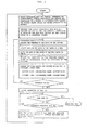
- Fig. 1 is a flowchart showing the flow of processing according to an embodiment of the present invention
- Fig. 2 is a block diagram illustrating the principal part of numerical control equipment embodying the present invention
- Fig. 3 is a diagram for explaining the relation between the locus of a tool or the like to be drawn and the scale for an image drawing space.
- Fig. 2 illustrates in block form the principal part of numerical control equipment provided with a graphic display which embodies the present invention.
- Reference numeral 10 indicates a microcomputer, which is connected to peripheral circuits via buses such as data, address and control buses, 11 a ROM for storing a program or the like which is necessary for the microcomputer 10 to execute predetermined operations, 12 a RAM which is used for a pointer, a computation or the like, 13 an address decoder for accessing a memory or the like, 14 a CMOS memory (which may also be formed by a magnetic bubble memory) for storing NC command programs, 15 a manual decoder input device (MDI) provided on a front panel of NC equipment and having various keys, 16 a CRT controller for generating horizontal and vertical synchronizing signals and a scanning address, 17 a pulse generator, 18 an address switching circuit for switching between a CPU address and the scanning address from the CRT controller 16, 19 an address decoder, 20 a character RAM for storing display characters corresponding to the position on the display screen
- the CMOS memory 14 has stored therein a plurality of NC command programs, and it is specified by modifying a set value which program is read out for displaying the locus of a tool.
- the set value is modified in a known manner. That is, set value modification data is displayed on the display screen 25 by pressing a set value modifying key of the MDI 15 and the number of a program desired to display is written from the MDI 15 into a program number insertion part in the set value modification data being displayed.
- the set value modification data further has parts where to set a parameter for the image drawing plane, parameters for maximum and minimum values of an image to be drawn, a parameter for center coordinates of the image drawing space, a parameter for the drawing start point, a drawing start block, an end block and so forth, and such necessary data is set from the MDI 15.
- a parameter for the image drawing plane parameters for maximum and minimum values of an image to be drawn
- a parameter for center coordinates of the image drawing space a parameter for the drawing start point
- a drawing start block a drawing start block
- an end block and so forth is set from the MDI 15.
- the number of the XY plane for instance, "0" is set as the parameter for the image drawing plane and when it is desired to display the tool locus in the YZ plane, "1" is set.
- maximum and minimum values for drawing maximum and minimum values are set for each axis of the specified plane.
- the scale and the center coordinates of the image drawing space will be automatically determined.
- the center coordinates of the image drawing space the corresponding values in the coordinate system of a workpiece in a selected NC command program for which the locus of a tool or the like is to be drawn are set.
- centers of these maximum and minimum values will automatically be set as the center coordinates of the image drawing space.
- the drawing start point when G92 is not directed at the beginning of the selected NC command program, this set value will specify the start point, so that when a command such as G92 is not provided, a value in the coordinate system of the workpiece is set as the drawing start point.
- the drawing starting and terminating blocks are set by specifying the program number and the sequence number.
- the MDI 15 is first operated to call up set value modification data onto the display screen 25, and No. 1 is set as the program number and further the image drawing plane, the maximum and minimum values of an image to be drawn and the drawing start and end blocks are set.
- the maximum and minimum values are provisional values that the operator considers appropriate.
- a drawing start key on the MDI 15 is turned ON, starting the microcomputer 10 to execute such a process as shown in Fig. 1.
- the correspondence between coordinates of the drawing space and coordinates of the NC command program (the scale, the center coordinates of the image drawing space, etc.) is determined in accordance with the image drawing plane and the maximum and minimum values set as described above. Then preparations are made for newly obtaining maximum and minimum values of the NC command program (for example, setting, as the coordinates of the starting point, the provisional maximum and minimum values set as the parameters).
- one block of an NC command program corresponding to the program number set as the parameter is read out of the CMOS memory 14 and its contents are analyzed to compute tool locus data, which is written into the graphic RAM 21. Furthermore, the position in the coordinate system of the program is updated in accordance with the contents of the program, and its coordinates are compared with the previous maximum and minimum values to compute maximum and minimum values of the program for each axis.
- MAX(a, b) is a symbol of the aforementioned conventional methods 1 to 3 after the first drawing processing (the selection of the method 2 is virtually meaningless) will increase the degree of freedom in operation, and hence is preferable.
- a satisfactory display image can be obtained by a single drawing process. Even when the set values are inappropriate, if the locus of a tool is displayed to some extent, the operator can obtain some information on the program.
- the maximum and minimum coordinate values of the NC command program are obtained in the above drawing processing, when a predetermined command is input next for redrawing, the tool locus is displayed based on such a magnification and center coordinates that the thus obtained maximum and minimum coordinate values will go in the specified image drawing space.
- the tool locus or the like can surely be displayed in its entirety and an optimum scale for drawing can be set as quickly as possible.
Landscapes
- Engineering & Computer Science (AREA)
- Human Computer Interaction (AREA)
- Manufacturing & Machinery (AREA)
- Physics & Mathematics (AREA)
- General Physics & Mathematics (AREA)
- Automation & Control Theory (AREA)
- Numerical Control (AREA)
Applications Claiming Priority (2)
| Application Number | Priority Date | Filing Date | Title |
|---|---|---|---|
| JP136275/84 | 1984-06-30 | ||
| JP59136275A JPS6115205A (ja) | 1984-06-30 | 1984-06-30 | 数値制御装置用グラフイツクデイスプレイの描画方法 |
Publications (3)
| Publication Number | Publication Date |
|---|---|
| EP0188619A1 true EP0188619A1 (de) | 1986-07-30 |
| EP0188619A4 EP0188619A4 (de) | 1988-12-19 |
| EP0188619B1 EP0188619B1 (de) | 1991-10-09 |
Family
ID=15171382
Family Applications (1)
| Application Number | Title | Priority Date | Filing Date |
|---|---|---|---|
| EP85903369A Expired EP0188619B1 (de) | 1984-06-30 | 1985-06-28 | Verfahren zur graphischen darstellung bei numerisch gesteuerten anlagen |
Country Status (5)
| Country | Link |
|---|---|
| US (1) | US4725960A (de) |
| EP (1) | EP0188619B1 (de) |
| JP (1) | JPS6115205A (de) |
| DE (1) | DE3584364D1 (de) |
| WO (1) | WO1986000429A1 (de) |
Cited By (2)
| Publication number | Priority date | Publication date | Assignee | Title |
|---|---|---|---|---|
| EP0440904A1 (de) * | 1990-02-09 | 1991-08-14 | Mitsubishi Denki Kabushiki Kaisha | Verfahren und Vorrichtung zur skalierten Wiedergabe graphischer Darstellungen auf einem Bildschirm oder einem anderen Wiedergabegerät |
| EP0513369A4 (en) * | 1990-11-08 | 1993-02-24 | Fanuc Ltd. | Numerically controlled device with working simulation function |
Families Citing this family (13)
| Publication number | Priority date | Publication date | Assignee | Title |
|---|---|---|---|---|
| DE3650486T2 (de) * | 1985-04-13 | 1996-08-01 | Quantel Ltd | Videobildgestaltungssysteme |
| JPS6332608A (ja) * | 1986-07-26 | 1988-02-12 | Fanuc Ltd | 数値制御装置 |
| JPS63109591A (ja) * | 1986-10-27 | 1988-05-14 | Sharp Corp | 光学的文字読取装置 |
| GB2230981B (en) * | 1988-07-08 | 1993-01-27 | Honda Motor Co Ltd | Method of producing pattern for molding castings |
| US5268677A (en) * | 1988-08-04 | 1993-12-07 | The Grass Valley Group, Inc. | Reduced viewport for graphics display |
| JPH02143900A (ja) * | 1988-11-25 | 1990-06-01 | Fanuc Ltd | Xyプロッタへの図面出力設定方法 |
| US4991022A (en) * | 1989-04-20 | 1991-02-05 | Rca Licensing Corporation | Apparatus and a method for automatically centering a video zoom and pan display |
| JPH0519837A (ja) * | 1991-07-10 | 1993-01-29 | Fanuc Ltd | 多系統旋盤用nc装置におけるアニメ描画方式 |
| JP2643596B2 (ja) * | 1990-11-29 | 1997-08-20 | 株式会社日立製作所 | スカラ量分布表示方法 |
| US5384909A (en) * | 1991-12-19 | 1995-01-24 | International Business Machines Corporation | Precision automatic scrolling for an image display system |
| JPH06348800A (ja) * | 1993-06-02 | 1994-12-22 | Canon Inc | 画像処理方法及び装置 |
| JPH07295619A (ja) * | 1994-04-25 | 1995-11-10 | Mitsubishi Electric Corp | 工作機械の数値制御装置 |
| JP6434246B2 (ja) * | 2014-07-29 | 2018-12-05 | ファナック株式会社 | 機械異常履歴の解析支援機能を有する数値制御装置 |
Family Cites Families (5)
| Publication number | Priority date | Publication date | Assignee | Title |
|---|---|---|---|---|
| US3867616A (en) * | 1968-09-03 | 1975-02-18 | Badger Co | Automated designing |
| DD134895B1 (de) * | 1978-03-07 | 1988-01-27 | Akad Wissenschaften Ddr | Verfahren zur darstellung von kurven auf sichtgeraeten |
| JPS56119185A (en) * | 1980-02-23 | 1981-09-18 | Fujitsu Fanuc Ltd | Picture display system |
| JPS58149508A (ja) * | 1982-02-27 | 1983-09-05 | Fanuc Ltd | Ncデ−タ作成方式 |
| JPS58158713A (ja) * | 1982-03-16 | 1983-09-21 | Mitsubishi Electric Corp | 数値制御加工装置の加工情報表示方法 |
-
1984
- 1984-06-30 JP JP59136275A patent/JPS6115205A/ja active Pending
-
1985
- 1985-06-28 WO PCT/JP1985/000364 patent/WO1986000429A1/ja not_active Ceased
- 1985-06-28 US US06/832,715 patent/US4725960A/en not_active Expired - Fee Related
- 1985-06-28 DE DE8585903369T patent/DE3584364D1/de not_active Expired - Lifetime
- 1985-06-28 EP EP85903369A patent/EP0188619B1/de not_active Expired
Non-Patent Citations (1)
| Title |
|---|
| See references of WO8600429A1 * |
Cited By (3)
| Publication number | Priority date | Publication date | Assignee | Title |
|---|---|---|---|---|
| EP0440904A1 (de) * | 1990-02-09 | 1991-08-14 | Mitsubishi Denki Kabushiki Kaisha | Verfahren und Vorrichtung zur skalierten Wiedergabe graphischer Darstellungen auf einem Bildschirm oder einem anderen Wiedergabegerät |
| EP0513369A4 (en) * | 1990-11-08 | 1993-02-24 | Fanuc Ltd. | Numerically controlled device with working simulation function |
| US5315523A (en) * | 1990-11-08 | 1994-05-24 | Fanuc Ltd. | Numerical control apparatus having a work simulation function |
Also Published As
| Publication number | Publication date |
|---|---|
| JPS6115205A (ja) | 1986-01-23 |
| EP0188619B1 (de) | 1991-10-09 |
| DE3584364D1 (de) | 1991-11-14 |
| WO1986000429A1 (fr) | 1986-01-16 |
| US4725960A (en) | 1988-02-16 |
| EP0188619A4 (de) | 1988-12-19 |
Similar Documents
| Publication | Publication Date | Title |
|---|---|---|
| EP0188619B1 (de) | Verfahren zur graphischen darstellung bei numerisch gesteuerten anlagen | |
| US5315523A (en) | Numerical control apparatus having a work simulation function | |
| EP0122941A1 (de) | Graphische anzeigevorrichtung | |
| US4644460A (en) | Cutting direction input method in automatic programming | |
| GB2155661A (en) | Shape inputting system | |
| US4961072A (en) | Graphics display method for numerical control apparatus | |
| EP0269737A1 (de) | Verfahren zur anzeige der arbeitszeit bei einer vierachsenbank | |
| EP0146628B1 (de) | Automatisches programmierverfahren | |
| JP2773517B2 (ja) | プログラム表示装置 | |
| EP0144427A1 (de) | Verfahren zur bestimmung des zeichens eingetragener daten | |
| EP0139761A1 (de) | Verfahren zur bestimmung einer mittels selbstregulierung zu bearbeitenden stelle | |
| JPH0549993B2 (de) | ||
| EP0458982A1 (de) | Bearbeitungsanzeigesystem | |
| US5278479A (en) | Tool path drawing method | |
| EP0530364A1 (de) | Interaktive numerische steuerung | |
| EP0441977B1 (de) | Anzeigesystem für ein numerisch gesteuertes gerät | |
| EP0146631A1 (de) | Dateneintragesystem für numerisch gesteuerte vorrichtung | |
| EP0383938A1 (de) | Eingabesystem für die form eines gegenstandes | |
| JPH10154040A (ja) | 画像処理装置 | |
| EP0331759A1 (de) | Selbsttätige programmieranordnung | |
| JPH08328630A (ja) | 加工軌跡表示方式 | |
| JPS61249109A (ja) | 数値制御装置の対話プログラム作成方式 | |
| JPH0695293B2 (ja) | 数値制御装置における加工シミュレーション方法 | |
| JPH07109563B2 (ja) | 修正形状要素の表示方法 | |
| JPS63282504A (ja) | 表示方式 |
Legal Events
| Date | Code | Title | Description |
|---|---|---|---|
| PUAI | Public reference made under article 153(3) epc to a published international application that has entered the european phase |
Free format text: ORIGINAL CODE: 0009012 |
|
| 17P | Request for examination filed |
Effective date: 19860224 |
|
| AK | Designated contracting states |
Kind code of ref document: A1 Designated state(s): DE FR GB |
|
| A4 | Supplementary search report drawn up and despatched |
Effective date: 19881219 |
|
| 17Q | First examination report despatched |
Effective date: 19900726 |
|
| GRAA | (expected) grant |
Free format text: ORIGINAL CODE: 0009210 |
|
| AK | Designated contracting states |
Kind code of ref document: B1 Designated state(s): DE FR GB |
|
| REF | Corresponds to: |
Ref document number: 3584364 Country of ref document: DE Date of ref document: 19911114 |
|
| ET | Fr: translation filed | ||
| PG25 | Lapsed in a contracting state [announced via postgrant information from national office to epo] |
Ref country code: GB Effective date: 19920628 |
|
| PLBE | No opposition filed within time limit |
Free format text: ORIGINAL CODE: 0009261 |
|
| STAA | Information on the status of an ep patent application or granted ep patent |
Free format text: STATUS: NO OPPOSITION FILED WITHIN TIME LIMIT |
|
| 26N | No opposition filed | ||
| GBPC | Gb: european patent ceased through non-payment of renewal fee |
Effective date: 19920628 |
|
| PG25 | Lapsed in a contracting state [announced via postgrant information from national office to epo] |
Ref country code: FR Effective date: 19930226 |
|
| REG | Reference to a national code |
Ref country code: FR Ref legal event code: ST |
|
| PGFP | Annual fee paid to national office [announced via postgrant information from national office to epo] |
Ref country code: DE Payment date: 19930630 Year of fee payment: 9 |
|
| PG25 | Lapsed in a contracting state [announced via postgrant information from national office to epo] |
Ref country code: DE Effective date: 19950301 |