EP0188630B1 - Appareil de conditionnement d'air - Google Patents
Appareil de conditionnement d'air Download PDFInfo
- Publication number
- EP0188630B1 EP0188630B1 EP84309057A EP84309057A EP0188630B1 EP 0188630 B1 EP0188630 B1 EP 0188630B1 EP 84309057 A EP84309057 A EP 84309057A EP 84309057 A EP84309057 A EP 84309057A EP 0188630 B1 EP0188630 B1 EP 0188630B1
- Authority
- EP
- European Patent Office
- Prior art keywords
- super
- heat exchanger
- valve
- indoor units
- temperature
- Prior art date
- Legal status (The legal status is an assumption and is not a legal conclusion. Google has not performed a legal analysis and makes no representation as to the accuracy of the status listed.)
- Expired - Lifetime
Links
- 238000004378 air conditioning Methods 0.000 title claims description 8
- 239000003507 refrigerant Substances 0.000 claims description 141
- 239000007788 liquid Substances 0.000 claims description 139
- 238000010438 heat treatment Methods 0.000 claims description 85
- 238000001816 cooling Methods 0.000 claims description 72
- 238000004781 supercooling Methods 0.000 claims description 41
- 230000005855 radiation Effects 0.000 claims description 7
- 230000004044 response Effects 0.000 claims description 5
- 238000010586 diagram Methods 0.000 description 14
- 238000009825 accumulation Methods 0.000 description 7
- 230000007246 mechanism Effects 0.000 description 4
- XLYOFNOQVPJJNP-UHFFFAOYSA-N water Substances O XLYOFNOQVPJJNP-UHFFFAOYSA-N 0.000 description 4
- 238000010276 construction Methods 0.000 description 3
- 238000011068 loading method Methods 0.000 description 3
- 230000009467 reduction Effects 0.000 description 3
- 230000000694 effects Effects 0.000 description 2
- 230000006870 function Effects 0.000 description 2
- 229910052751 metal Inorganic materials 0.000 description 2
- 238000010926 purge Methods 0.000 description 2
- 230000008054 signal transmission Effects 0.000 description 2
- 229940002865 4-way Drugs 0.000 description 1
- 230000008859 change Effects 0.000 description 1
- 230000003750 conditioning effect Effects 0.000 description 1
- 230000006872 improvement Effects 0.000 description 1
- 230000002265 prevention Effects 0.000 description 1
- 238000005057 refrigeration Methods 0.000 description 1
- 239000012808 vapor phase Substances 0.000 description 1
Images


Classifications
-
- F—MECHANICAL ENGINEERING; LIGHTING; HEATING; WEAPONS; BLASTING
- F24—HEATING; RANGES; VENTILATING
- F24F—AIR-CONDITIONING; AIR-HUMIDIFICATION; VENTILATION; USE OF AIR CURRENTS FOR SCREENING
- F24F3/00—Air-conditioning systems in which conditioned primary air is supplied from one or more central stations to distributing units in the rooms or spaces where it may receive secondary treatment; Apparatus specially designed for such systems
- F24F3/06—Air-conditioning systems in which conditioned primary air is supplied from one or more central stations to distributing units in the rooms or spaces where it may receive secondary treatment; Apparatus specially designed for such systems characterised by the arrangements for the supply of heat-exchange fluid for the subsequent treatment of primary air in the room units
- F24F3/065—Air-conditioning systems in which conditioned primary air is supplied from one or more central stations to distributing units in the rooms or spaces where it may receive secondary treatment; Apparatus specially designed for such systems characterised by the arrangements for the supply of heat-exchange fluid for the subsequent treatment of primary air in the room units with a plurality of evaporators or condensers
-
- F—MECHANICAL ENGINEERING; LIGHTING; HEATING; WEAPONS; BLASTING
- F24—HEATING; RANGES; VENTILATING
- F24F—AIR-CONDITIONING; AIR-HUMIDIFICATION; VENTILATION; USE OF AIR CURRENTS FOR SCREENING
- F24F1/00—Room units for air-conditioning, e.g. separate or self-contained units or units receiving primary air from a central station
- F24F1/0007—Indoor units, e.g. fan coil units
-
- F—MECHANICAL ENGINEERING; LIGHTING; HEATING; WEAPONS; BLASTING
- F24—HEATING; RANGES; VENTILATING
- F24F—AIR-CONDITIONING; AIR-HUMIDIFICATION; VENTILATION; USE OF AIR CURRENTS FOR SCREENING
- F24F1/00—Room units for air-conditioning, e.g. separate or self-contained units or units receiving primary air from a central station
- F24F1/0007—Indoor units, e.g. fan coil units
- F24F1/0071—Indoor units, e.g. fan coil units with means for purifying supplied air
-
- F—MECHANICAL ENGINEERING; LIGHTING; HEATING; WEAPONS; BLASTING
- F24—HEATING; RANGES; VENTILATING
- F24F—AIR-CONDITIONING; AIR-HUMIDIFICATION; VENTILATION; USE OF AIR CURRENTS FOR SCREENING
- F24F11/00—Control or safety arrangements
- F24F11/62—Control or safety arrangements characterised by the type of control or by internal processing, e.g. using fuzzy logic, adaptive control or estimation of values
- F24F11/63—Electronic processing
-
- F—MECHANICAL ENGINEERING; LIGHTING; HEATING; WEAPONS; BLASTING
- F24—HEATING; RANGES; VENTILATING
- F24F—AIR-CONDITIONING; AIR-HUMIDIFICATION; VENTILATION; USE OF AIR CURRENTS FOR SCREENING
- F24F11/00—Control or safety arrangements
- F24F11/70—Control systems characterised by their outputs; Constructional details thereof
- F24F11/80—Control systems characterised by their outputs; Constructional details thereof for controlling the temperature of the supplied air
- F24F11/83—Control systems characterised by their outputs; Constructional details thereof for controlling the temperature of the supplied air by controlling the supply of heat-exchange fluids to heat-exchangers
- F24F11/84—Control systems characterised by their outputs; Constructional details thereof for controlling the temperature of the supplied air by controlling the supply of heat-exchange fluids to heat-exchangers using valves
-
- F—MECHANICAL ENGINEERING; LIGHTING; HEATING; WEAPONS; BLASTING
- F24—HEATING; RANGES; VENTILATING
- F24F—AIR-CONDITIONING; AIR-HUMIDIFICATION; VENTILATION; USE OF AIR CURRENTS FOR SCREENING
- F24F11/00—Control or safety arrangements
- F24F11/88—Electrical aspects, e.g. circuits
-
- F—MECHANICAL ENGINEERING; LIGHTING; HEATING; WEAPONS; BLASTING
- F25—REFRIGERATION OR COOLING; COMBINED HEATING AND REFRIGERATION SYSTEMS; HEAT PUMP SYSTEMS; MANUFACTURE OR STORAGE OF ICE; LIQUEFACTION SOLIDIFICATION OF GASES
- F25B—REFRIGERATION MACHINES, PLANTS OR SYSTEMS; COMBINED HEATING AND REFRIGERATION SYSTEMS; HEAT PUMP SYSTEMS
- F25B13/00—Compression machines, plants or systems, with reversible cycle
-
- F—MECHANICAL ENGINEERING; LIGHTING; HEATING; WEAPONS; BLASTING
- F25—REFRIGERATION OR COOLING; COMBINED HEATING AND REFRIGERATION SYSTEMS; HEAT PUMP SYSTEMS; MANUFACTURE OR STORAGE OF ICE; LIQUEFACTION SOLIDIFICATION OF GASES
- F25B—REFRIGERATION MACHINES, PLANTS OR SYSTEMS; COMBINED HEATING AND REFRIGERATION SYSTEMS; HEAT PUMP SYSTEMS
- F25B41/00—Fluid-circulation arrangements
- F25B41/30—Expansion means; Dispositions thereof
- F25B41/31—Expansion valves
- F25B41/34—Expansion valves with the valve member being actuated by electric means, e.g. by piezoelectric actuators
- F25B41/35—Expansion valves with the valve member being actuated by electric means, e.g. by piezoelectric actuators by rotary motors, e.g. by stepping motors
-
- F—MECHANICAL ENGINEERING; LIGHTING; HEATING; WEAPONS; BLASTING
- F24—HEATING; RANGES; VENTILATING
- F24F—AIR-CONDITIONING; AIR-HUMIDIFICATION; VENTILATION; USE OF AIR CURRENTS FOR SCREENING
- F24F11/00—Control or safety arrangements
- F24F11/30—Control or safety arrangements for purposes related to the operation of the system, e.g. for safety or monitoring
-
- F—MECHANICAL ENGINEERING; LIGHTING; HEATING; WEAPONS; BLASTING
- F24—HEATING; RANGES; VENTILATING
- F24F—AIR-CONDITIONING; AIR-HUMIDIFICATION; VENTILATION; USE OF AIR CURRENTS FOR SCREENING
- F24F2110/00—Control inputs relating to air properties
- F24F2110/10—Temperature
-
- F—MECHANICAL ENGINEERING; LIGHTING; HEATING; WEAPONS; BLASTING
- F24—HEATING; RANGES; VENTILATING
- F24F—AIR-CONDITIONING; AIR-HUMIDIFICATION; VENTILATION; USE OF AIR CURRENTS FOR SCREENING
- F24F2140/00—Control inputs relating to system states
-
- F—MECHANICAL ENGINEERING; LIGHTING; HEATING; WEAPONS; BLASTING
- F24—HEATING; RANGES; VENTILATING
- F24F—AIR-CONDITIONING; AIR-HUMIDIFICATION; VENTILATION; USE OF AIR CURRENTS FOR SCREENING
- F24F2221/00—Details or features not otherwise provided for
- F24F2221/54—Heating and cooling, simultaneously or alternatively
-
- F—MECHANICAL ENGINEERING; LIGHTING; HEATING; WEAPONS; BLASTING
- F25—REFRIGERATION OR COOLING; COMBINED HEATING AND REFRIGERATION SYSTEMS; HEAT PUMP SYSTEMS; MANUFACTURE OR STORAGE OF ICE; LIQUEFACTION SOLIDIFICATION OF GASES
- F25B—REFRIGERATION MACHINES, PLANTS OR SYSTEMS; COMBINED HEATING AND REFRIGERATION SYSTEMS; HEAT PUMP SYSTEMS
- F25B2313/00—Compression machines, plants or systems with reversible cycle not otherwise provided for
- F25B2313/023—Compression machines, plants or systems with reversible cycle not otherwise provided for using multiple indoor units
-
- F—MECHANICAL ENGINEERING; LIGHTING; HEATING; WEAPONS; BLASTING
- F25—REFRIGERATION OR COOLING; COMBINED HEATING AND REFRIGERATION SYSTEMS; HEAT PUMP SYSTEMS; MANUFACTURE OR STORAGE OF ICE; LIQUEFACTION SOLIDIFICATION OF GASES
- F25B—REFRIGERATION MACHINES, PLANTS OR SYSTEMS; COMBINED HEATING AND REFRIGERATION SYSTEMS; HEAT PUMP SYSTEMS
- F25B2313/00—Compression machines, plants or systems with reversible cycle not otherwise provided for
- F25B2313/027—Compression machines, plants or systems with reversible cycle not otherwise provided for characterised by the reversing means
- F25B2313/02741—Compression machines, plants or systems with reversible cycle not otherwise provided for characterised by the reversing means using one four-way valve
-
- Y—GENERAL TAGGING OF NEW TECHNOLOGICAL DEVELOPMENTS; GENERAL TAGGING OF CROSS-SECTIONAL TECHNOLOGIES SPANNING OVER SEVERAL SECTIONS OF THE IPC; TECHNICAL SUBJECTS COVERED BY FORMER USPC CROSS-REFERENCE ART COLLECTIONS [XRACs] AND DIGESTS
- Y02—TECHNOLOGIES OR APPLICATIONS FOR MITIGATION OR ADAPTATION AGAINST CLIMATE CHANGE
- Y02B—CLIMATE CHANGE MITIGATION TECHNOLOGIES RELATED TO BUILDINGS, e.g. HOUSING, HOUSE APPLIANCES OR RELATED END-USER APPLICATIONS
- Y02B30/00—Energy efficient heating, ventilation or air conditioning [HVAC]
- Y02B30/70—Efficient control or regulation technologies, e.g. for control of refrigerant flow, motor or heating
Definitions
- the expansion vave 58 utilizes a bi-metallic element and an electric heater for heating said bi-metallic element the valve opening being controlled by adjustment of the current through said electric heater during both cooling and heating operations. It is therefore not necessary to provide separate expansion valves for cooling and heating, which simplifies the refrigeration circuit to that extent.
- the expansion valve 58 is constructed so as to completely close during cooling and remain fully open during heating operations, it is necessary to provide a solenoid valve 61 in said gas line branch 60.
- the expansion valve 58 controls the degree of superheat only during both cooling and heating operations and cannot control the degree of supercooling, especially during heating operations it controls the degree of super-heat of low pressure gaseous refrigerant at the outlet of said supply-side heat exchanger 53 of the outdoor unit A, it is impossible to provide an appropriate refrigerant distribution to each of the indoor units B. Nowhere in the prior art is there any specific disclosure of any system which can provide appropriate refrigerant distribution to each of the indoor units B, whilst still controlling the degree of super-heat.
- the compressed gas In a heating mode, the compressed gas first passes through the indoor exchanger which operates as a condenser, a portion of the gas flow then travelling in the opposite direction to that travelled in the cooling mode so as to enter the outdoor exchanger, which is operating as a condenser, a further portion passing through a branch line to a container or reservoir.
- the opening of the motorized valves connected to the operating indoor units can be controlled by the loading applied to each respective indoor unit but it may also be controlled in accordance with the number of indoor units in operation.
- a motorized valve (hereinafter referred to as the second or secondary motorized valve) is preferably used as the control means and when such a second motorized valve is used, it is possible for this to be arranged so that the second motorized valve controls super-cooling at said supply-side heat exchanger outlet during cooling and super- heat at said heat exchanger outlet during heating operations.
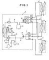
- Fig. 1 shows a typical embodiment of the present invention wherein the refrigerant circuit comprises an outdoor unitA having a compressor 1, a 4-way valve 2, a supply-side heat exchanger 3, a liquid refrigerant line main 4, a plurality of liquid line branches 5 branching out of said liquid line main 4, gaseous refrigerant line main 6 and a plurality of gas line branches 7 branching out of said gas line main and a plurality of indoor units B each having a consumer-side heat exchanger and a fan which are connected in parallel between said liquid line branches 5 and said gas line branches 7 through a plurality of connection pipes C.
- the system is capable of providing cooling or heating.
- the second sensing circuit 20 also serves as the second temperature sensing means by mounting a fourth temperature sensor THe between said temperature sensing circuit heat exchanger 21 and said pressure reducing mechanism 22 in order to sense the saturation temperature To of high pressure liquid refrigerant passing through said heat exchanger 21.
- the second sensing circuit 20 is provided on the outdoor unit A, the first temperature sensors TH 1 ⁇ TH 3 mounted in the gas line branches 7, the third temperature sensors TH 4 ⁇ TH 6 mounted in the liquid line branches 5, all the wiring connecting said first and third temperature sensors TH 1 ⁇ TH 6 and the valve control means of said motorized valves EV,-EV 3 for signal transmissions are housed within the outdoor Unit A, which avoids the need for any control wiring between the outdoor and indoor units.
- the motorized valves EV 1 ⁇ EV 3 are mounted in the liquid line branches only and no motorized valves or solenoid valves as used in conventional systems require to be mounted in the gas line branches 7, it is possible to reduce the number of components correspondingly and thereby simplify the refigerant circuit. Since the motorized valves EV,-EV 3 completely close during cooling and open to only a small opening during heating operations for non-operating units B, no liquid accumulation takes place in the non-operating indoor units B.
- the motorized valve EV 1 ⁇ EV 3 is shut down to a small opening, i.e. an opening sufficiently small to admit liquid refrigerant condensing as a result of natural radiation.
- the size of the small residual opening of the motorized valve EV 1 ⁇ EV 3 during heating operations may be fixed at a suitably small predetermined valve.
- the first sensing circuit 16 of this embodiment is for control of valve opening of the second motorized valve EV 4 and as stated above, contains a pressure reducing device 17 such as a capillary tube and the second temperature sensor THe is mounted in the first sensing circuit 16 between said pressure reducing mechanism 17 and said suction line 19, and a fifth temperature sensor TH 7 is mounted on the suction line 19 in order to sense low pressure gaseous refrigerant temperature T 7 .
- a pressure reducing device 17 such as a capillary tube
- the second temperature sensor THe is mounted in the first sensing circuit 16 between said pressure reducing mechanism 17 and said suction line 19
- a fifth temperature sensor TH 7 is mounted on the suction line 19 in order to sense low pressure gaseous refrigerant temperature T 7 .
- a bypass circuit bypassing said conventional superheat control valve is provided in said liquid line main 4 and a check valve is mounted on said bypass circuit to pass refrigerant during cooling operations.
- first motorized valves EV 1 ⁇ EV 3 corresponding to the non-operating units are completely closed (stop 106) and the first motorized valves EV 1 ⁇ EV 3 corresponding to the operating units are controlled to a predetermined opening in accordance with the pulse number changing with the number of indoor units B operating (step 107).
- the second motorized valve EV 4 is fully opened (step 108).
- Fig. 6 is the flow chart for heating operations, which starts with sensing of heating mode operation as for the cooling operations.
- the operational status checked out step 201
- the existence of any change in the operational status is judged (step 202).
- the first and second motorized valves EV I -EV 3 , EV 4 are cut off from control thereof (steps 203, 204).
- the first motorized valves EV 1 ⁇ EV 3 are controlled at a given opening in accordance with the pulse number which changes with the number of indoor units B operating (step 207).
- the deviation E 1 is calculated (step 209) and when the absolute value of this deviation E, is largerthan 1°C and said deviation E 1 is less than 0, the second motorized valve EV 4 is closed by one predetermined notch (step 210) and when said deviation is more than 0, the second motorized valve EV 4 is opened by one predetermined notch and thereby the deviation E, of said low pressure gaseous refrigerant super-heat can be controlled within ⁇ 1°C of the target superheat SH which is set to have 0°-3°C at the outlet of the supply-side heat exchanger 3.
- the second motorized valve EV 4 may be controlled during heating, to a pre-determined opening so as to obtain appropriate superheat.
- said motorized valve EV 4 may operate so as to control super-cooling of high pressure liquid refrigerant at the supply-side heat exchanger 3 outlet during cooling and an externally equalizing or internally equalizing expansion valve may also be applied to super-cooling control.
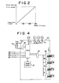
- the control system which controls the first motorized valve EV 1 ⁇ EV 3 mounted in each liquid line branch 5 and the second motorized valve EV 4 mounted on the liquid line main 4 for controling superheat of low pressure gaseous refrigerant at the supply-side heat exchanger 3 outlet during heating is basically the same as that of the second embodiment shown in Fig. 4. The difference is the following additional hook-up so constructed that as shown in Fig. 8, on the input side of central processing unit CPU of said controller30, said first and third temperature sensors TH 1 ⁇ TH 6 are connected and said central processing unit CPU incorporates the following four functions:
- This control operation is the same for both cooling and heating operations. After this predetermined period, the operation proceeds as follows. During cooling operations as shown in the flow chart of Fig. 9, the temperatures of low pressure gaseous refrigerant T,-T 3 flowing through said gas line branches 7 from the respective operating indoor units B are sensed by the first temperature sensors TH 1 ⁇ TH 3 (step 109) and the saturation temperature Te of low pressure gaseous refrigerant is sensed by the second temperature sensor THe (step 109).
- the minimum pulse number in the closing direction is set at about 50 pulses and the maximum pulse number at about 200 pulses.
- the refrigerant circuit of the fourth embodiment shown in Fig. 11 is basically similar to those of the second and third embodiments shown in Figs. 3 and 7, respectively.
- the difference is that in the third embodiment shown in Fig. 7, the sixth temperature sensor TH 8 and the seventh temperature sensor TH 9 are provided, in the liquid line 4, in order to sense respectively, high pressure liquid refrigerant temperature T 8 at the supply-side heat exchanger 3 outlet and condensing temperature T c therein and thereby super- cooling is also controlled using the second motorized valve EV 4 . Therefore, the control system for the first motorized valves EV,-EV 3 and the second motorized valve differs, as shown in Fig.
- the second motorized valve EV 4 When the deviation E 2 is positive and the absolute value thereof larger than 1, the second motorized valve EV 4 is modulated so as to close by one notch (step 315) and when it is negative and the absolute value thereof larger than 1, the second motorized valve EV 4 is modulated so as to open by one notch (step 316) and thereby super-cooling of said high pressure liquid refrigerant is maintained within ⁇ 1°C of the target super-cooling level by controlling the pulse input into the second motorized valve EV 4 .
- the second motorized valve EV 4 control may be conducted by first controlling the input pulse number (for example to 180 pulses) so as to obtain the proper degree of opening.
- the fifth embodiment shown in Fig. 14 is basically similar to the first embodiment and the main difference from the first embodiment lies in that a parallel circuit of the second motorized valve EV 4 and a check valve 25 are, as in the second embodiment, provided in said liquid line main 4 to control low pressure gaseous refrigerant super-heat at the supply-side heat exchanger 3 outlet during heating; two 4-way valves, i.e.
- first and second 4-way valves 2A, 2B are provided; a domestic hot water supply heat exchanger 43 is provided between the second four-way valve and a receiver 10; the first sensing circuit 16A has a pressure-reducing device 17A provided between the liquid line main 4 and the suction line 19; and a second sensing circuit 20A has a detector heat exchanger 21A provided with one end connected to the line connecting said pressure reducing device 17A with said liquid line main 4 and its other end to the gas line main 6.
- refrigerant is conducted for cooling along the route indicated by the full line arrow, for cooling and providing a domestic hot water supply along the route indicated by the dotted line arrow, for domestic hot water supply (alone) along the route indicated by the chain line arrow, and for heating along the route indicated by double chain line arrow.
Landscapes
- Engineering & Computer Science (AREA)
- Mechanical Engineering (AREA)
- General Engineering & Computer Science (AREA)
- Chemical & Material Sciences (AREA)
- Combustion & Propulsion (AREA)
- Physics & Mathematics (AREA)
- Signal Processing (AREA)
- Thermal Sciences (AREA)
- Fuzzy Systems (AREA)
- Mathematical Physics (AREA)
- Air Conditioning Control Device (AREA)
- Compression-Type Refrigeration Machines With Reversible Cycles (AREA)
Claims (15)
Applications Claiming Priority (6)
| Application Number | Priority Date | Filing Date | Title |
|---|---|---|---|
| JP242770/83 | 1983-12-21 | ||
| JP242766/83 | 1983-12-21 | ||
| JP24277083A JPS60133269A (ja) | 1983-12-21 | 1983-12-21 | 分離形空気調和装置 |
| JP24276683A JPS60133274A (ja) | 1983-12-21 | 1983-12-21 | 多室形冷暖房装置 |
| JP24852784A JPS61128069A (ja) | 1984-11-24 | 1984-11-24 | 多室形空気調和装置 |
| JP248527/84 | 1984-11-24 |
Publications (3)
| Publication Number | Publication Date |
|---|---|
| EP0188630A2 EP0188630A2 (fr) | 1986-07-30 |
| EP0188630A3 EP0188630A3 (en) | 1987-06-24 |
| EP0188630B1 true EP0188630B1 (fr) | 1990-10-31 |
Family
ID=27333073
Family Applications (1)
| Application Number | Title | Priority Date | Filing Date |
|---|---|---|---|
| EP84309057A Expired - Lifetime EP0188630B1 (fr) | 1983-12-21 | 1984-12-21 | Appareil de conditionnement d'air |
Country Status (4)
| Country | Link |
|---|---|
| US (1) | US4644756A (fr) |
| EP (1) | EP0188630B1 (fr) |
| AU (1) | AU564902B2 (fr) |
| DE (1) | DE3483533D1 (fr) |
Families Citing this family (68)
| Publication number | Priority date | Publication date | Assignee | Title |
|---|---|---|---|---|
| US5392612A (en) * | 1984-08-08 | 1995-02-28 | Richard H. Alsenz | Refrigeration system having a self adjusting control range |
| US5035119A (en) * | 1984-08-08 | 1991-07-30 | Alsenz Richard H | Apparatus for monitoring solenoid expansion valve flow rates |
| US5402652A (en) * | 1984-08-08 | 1995-04-04 | Alsenz; Richard H. | Apparatus for monitoring solenoid expansion valve flow rates |
| US4771610A (en) * | 1986-06-06 | 1988-09-20 | Mitsubishi Denki Kabushiki Kaisha | Multiroom air conditioner |
| JPS6334459A (ja) * | 1986-07-29 | 1988-02-15 | 株式会社東芝 | 空気調和機 |
| JP2735188B2 (ja) * | 1987-03-20 | 1998-04-02 | 株式会社日立製作所 | 空気調和装置 |
| JPH07111283B2 (ja) * | 1987-03-20 | 1995-11-29 | 株式会社日立製作所 | 多室形空気調和装置 |
| KR920008504B1 (ko) * | 1988-10-17 | 1992-09-30 | 미쓰비시전기주식회사 | 공기조화장치 |
| JPH07117303B2 (ja) * | 1989-03-01 | 1995-12-18 | ホシザキ電機株式会社 | 冷凍装置 |
| EP0482629B1 (fr) * | 1990-10-25 | 1995-12-13 | Kabushiki Kaisha Toshiba | Appareil de conditionnement d'air |
| US5134859A (en) * | 1991-03-29 | 1992-08-04 | General Electric Company | Excess refrigerant accumulator for multievaporator vapor compression refrigeration cycles |
| US5103650A (en) * | 1991-03-29 | 1992-04-14 | General Electric Company | Refrigeration systems with multiple evaporators |
| US20050133304A1 (en) * | 1991-10-23 | 2005-06-23 | Viken James P. | Fluid exchange system for vehicles |
| JPH05149605A (ja) * | 1991-11-30 | 1993-06-15 | Toshiba Corp | 空気調和機 |
| TW212224B (fr) * | 1992-02-28 | 1993-09-01 | Sanyo Denki Kk | |
| JP3080558B2 (ja) * | 1995-02-03 | 2000-08-28 | 株式会社日立製作所 | 寒冷地向けヒートポンプ空調機 |
| JPH09229500A (ja) * | 1995-12-27 | 1997-09-05 | Mando Mach Co Ltd | 多室エアコン |
| US5893271A (en) * | 1997-07-30 | 1999-04-13 | Detrex Corporation | Vapor degreaser refrigeration system |
| JP4200532B2 (ja) * | 1997-12-25 | 2008-12-24 | 三菱電機株式会社 | 冷凍装置 |
| KR100329472B1 (ko) * | 1998-04-20 | 2002-08-08 | 삼성전자 주식회사 | 냉난방겸용멀티에어컨 |
| KR100499506B1 (ko) * | 2003-01-13 | 2005-07-05 | 엘지전자 주식회사 | 멀티공기조화기용 이물질 차단장치 |
| CN100422653C (zh) * | 2003-04-08 | 2008-10-01 | 林荣恒 | 多用制冷制热空调装置 |
| KR100511286B1 (ko) * | 2003-05-01 | 2005-08-31 | 엘지전자 주식회사 | 동시 제상 및 난방 운전이 가능한 공기조화기 및 자체제상 사이클을 구비한 공기조화기용 실외기 |
| KR100511287B1 (ko) * | 2003-05-01 | 2005-08-31 | 엘지전자 주식회사 | 동시 제상 및 난방 운전이 가능한 공기조화기 및 자체제상 사이클을 구비한 공기조화기용 실외기 |
| JP4348610B2 (ja) * | 2003-09-29 | 2009-10-21 | 株式会社ヴァレオサーマルシステムズ | 冷凍サイクル |
| US20100192607A1 (en) * | 2004-10-14 | 2010-08-05 | Mitsubishi Electric Corporation | Air conditioner/heat pump with injection circuit and automatic control thereof |
| WO2007110908A1 (fr) * | 2006-03-27 | 2007-10-04 | Mitsubishi Denki Kabushiki Kaisha | Dispositif de climatisation frigorifique |
| JP4459776B2 (ja) | 2004-10-18 | 2010-04-28 | 三菱電機株式会社 | ヒートポンプ装置及びヒートポンプ装置の室外機 |
| KR100758902B1 (ko) * | 2004-11-23 | 2007-09-14 | 엘지전자 주식회사 | 멀티 공기조화 시스템 및 그 제어방법 |
| JP4596426B2 (ja) * | 2005-09-21 | 2010-12-08 | 日立アプライアンス株式会社 | 熱源装置 |
| KR100680496B1 (ko) * | 2005-10-31 | 2007-02-08 | 엘지전자 주식회사 | 멀티형 공기조화기에서 냉매 분배기의 제어장치 및 방법 |
| DE102006052321A1 (de) * | 2005-11-24 | 2007-06-06 | Danfoss A/S | Verfahren zum Analysieren einer Kühlanlage und Verfahren zur Regelung einer Kühlanlage |
| FR2895786B1 (fr) * | 2006-01-04 | 2008-04-11 | Valeo Systemes Thermiques | Module de detente pour installation de climatisation a deux evaporateurs |
| JP4049188B2 (ja) * | 2006-03-31 | 2008-02-20 | ダイキン工業株式会社 | 空気調和機の制御装置及び制御方法 |
| KR20080020771A (ko) * | 2006-09-01 | 2008-03-06 | 엘지전자 주식회사 | 수냉식 공기조화기 |
| US7824725B2 (en) | 2007-03-30 | 2010-11-02 | The Coca-Cola Company | Methods for extending the shelf life of partially solidified flowable compositions |
| KR101510378B1 (ko) * | 2008-02-20 | 2015-04-14 | 엘지전자 주식회사 | 공기 조화기 및 그의 제어방법 |
| US20090277196A1 (en) * | 2008-05-01 | 2009-11-12 | Gambiana Dennis S | Apparatus and method for modulating cooling |
| KR101581466B1 (ko) * | 2008-08-27 | 2015-12-31 | 엘지전자 주식회사 | 공기조화시스템 |
| GB2464712A (en) * | 2008-10-24 | 2010-04-28 | Agco Sa | Air conditioning control system |
| WO2010113296A1 (fr) * | 2009-04-01 | 2010-10-07 | 三菱電機株式会社 | Dispositif de climatisation |
| KR101321546B1 (ko) * | 2009-11-13 | 2013-10-28 | 엘지전자 주식회사 | 공기조화기 |
| KR20110097203A (ko) * | 2010-02-25 | 2011-08-31 | 삼성전자주식회사 | 히트 펌프 시스템 및 그 제어방법 |
| KR20110099558A (ko) * | 2010-03-02 | 2011-09-08 | 삼성전자주식회사 | 히트 펌프 시스템 및 그 제어방법 |
| JP5404487B2 (ja) * | 2010-03-23 | 2014-01-29 | 三菱電機株式会社 | 多室形空気調和機 |
| US8290628B2 (en) * | 2010-07-23 | 2012-10-16 | Lg Electronics Inc. | Air conditioner and method for controlling the same |
| JP5414638B2 (ja) * | 2010-08-25 | 2014-02-12 | 日立アプライアンス株式会社 | 空気調和システム |
| WO2012049702A1 (fr) * | 2010-10-12 | 2012-04-19 | 三菱電機株式会社 | Climatiseur |
| CN103229006B (zh) * | 2010-12-22 | 2015-11-25 | 三菱电机株式会社 | 供热水空调复合装置 |
| JP5674572B2 (ja) * | 2011-07-06 | 2015-02-25 | 三菱電機株式会社 | 空気調和機 |
| WO2014083652A1 (fr) * | 2012-11-29 | 2014-06-05 | 三菱電機株式会社 | Dispositif de climatisation |
| WO2015028552A1 (fr) * | 2013-08-30 | 2015-03-05 | Schneider Electric Danmark A/S | Procédé de régulation de température |
| CN103759455B (zh) * | 2014-01-27 | 2015-08-19 | 青岛海信日立空调系统有限公司 | 热回收变频多联式热泵系统及其控制方法 |
| EP3150935B1 (fr) * | 2014-05-30 | 2019-03-06 | Mitsubishi Electric Corporation | Climatiseur |
| JP6609417B2 (ja) | 2015-04-03 | 2019-11-20 | 日立ジョンソンコントロールズ空調株式会社 | 空気調和機 |
| EP3287715B1 (fr) * | 2015-04-20 | 2022-05-25 | Mitsubishi Electric Corporation | Appareil à cycle frigorifique |
| CN105570990B (zh) * | 2016-01-04 | 2018-07-13 | 广东美的暖通设备有限公司 | 多联空调系统 |
| CN106052216B (zh) * | 2016-06-29 | 2018-05-29 | 宁波奥克斯电气股份有限公司 | 一种多联机制热时对电子膨胀阀的控制方法 |
| JP2019120448A (ja) * | 2017-12-28 | 2019-07-22 | ダイキン工業株式会社 | 冷凍装置の熱源ユニット |
| CN108731127B (zh) * | 2018-06-06 | 2020-09-04 | 青岛海信日立空调系统有限公司 | 一种多管式多联机室外机及其管路检测方法和检测装置 |
| CN109579156B (zh) * | 2018-11-19 | 2024-07-23 | 珠海格力电器股份有限公司 | 一种极限温度制冷控制系统及多联机空调系统 |
| EP3875869B1 (fr) * | 2020-03-06 | 2022-07-13 | Daikin Industries, Ltd. | Système de pompe à chaleur et son procédé de commande |
| CN111780362B (zh) * | 2020-07-03 | 2022-03-11 | 海信(山东)空调有限公司 | 一种空调器及其控制方法 |
| CN112665161B (zh) * | 2020-12-08 | 2022-02-18 | 珠海格力电器股份有限公司 | 一种螺杆机组控制方法、装置和空调机组 |
| CN113108428B (zh) * | 2021-04-13 | 2023-03-17 | 广州市水电设备安装有限公司 | 一种多联机中央空调系统及其控制方法 |
| CN115540279A (zh) * | 2021-06-29 | 2022-12-30 | 美的集团股份有限公司 | 多联机的控制方法、多联机以及装置 |
| CN113551442A (zh) * | 2021-08-13 | 2021-10-26 | 王海卿 | 一种空气源热泵 |
| CN119374219A (zh) * | 2023-07-25 | 2025-01-28 | 开利公司 | 空气调节系统 |
Family Cites Families (6)
| Publication number | Priority date | Publication date | Assignee | Title |
|---|---|---|---|---|
| GB1395194A (en) * | 1971-09-06 | 1975-05-21 | Matsushita Electric Industrial Co Ltd | Heat pump type air conditioning systems |
| CH583887A5 (en) * | 1974-06-18 | 1977-01-14 | Kryotherm Ab | Air conditioning plant for both heating and cooling - has 4-way control valve linking the various components in different ways according to hot or cold setting |
| AU515910B2 (en) * | 1978-10-19 | 1981-05-07 | Matsushita Electric Industrial Co., Ltd. | Air conditioning system having a plurality of indoor units |
| AU538000B2 (en) * | 1979-04-02 | 1984-07-26 | Matsushita Electric Industrial Co., Ltd. | Air conditioner |
| US4510767A (en) * | 1981-07-03 | 1985-04-16 | Mitsubishi Denki Kabushiki Kaisha | Cold storage and refrigeration system |
| US4393662A (en) * | 1981-09-28 | 1983-07-19 | Dirth George P | Control system for refrigeration or air conditioning installation |
-
1984
- 1984-12-17 US US06/682,312 patent/US4644756A/en not_active Expired - Lifetime
- 1984-12-21 AU AU37101/84A patent/AU564902B2/en not_active Ceased
- 1984-12-21 EP EP84309057A patent/EP0188630B1/fr not_active Expired - Lifetime
- 1984-12-21 DE DE8484309057T patent/DE3483533D1/de not_active Expired - Lifetime
Also Published As
| Publication number | Publication date |
|---|---|
| US4644756A (en) | 1987-02-24 |
| AU3710184A (en) | 1985-07-04 |
| AU564902B2 (en) | 1987-08-27 |
| EP0188630A2 (fr) | 1986-07-30 |
| DE3483533D1 (de) | 1990-12-06 |
| EP0188630A3 (en) | 1987-06-24 |
Similar Documents
| Publication | Publication Date | Title |
|---|---|---|
| EP0188630B1 (fr) | Appareil de conditionnement d'air | |
| EP1659348B1 (fr) | Dispositif de congelation | |
| US7028492B2 (en) | Hybrid dehumidication system | |
| JPH03282164A (ja) | 空気調和機 | |
| KR950014470B1 (ko) | 공기조화기 | |
| JPWO2019053876A1 (ja) | 空気調和装置 | |
| US20090044557A1 (en) | Vapor compression system | |
| JP2000018737A (ja) | 空気調和機 | |
| JP2966641B2 (ja) | 空気調和装置 | |
| JP3334184B2 (ja) | 多室用空気調和機 | |
| JP3356485B2 (ja) | 多室型空気調和機 | |
| JP2974381B2 (ja) | 空気調和機 | |
| JPH0784956B2 (ja) | 空気調和装置の運転制御装置 | |
| EP2137467A1 (fr) | Système de conditionnement d'air à plusieurs unités et procédé de régulation correspondant | |
| JP2755040B2 (ja) | ヒートポンプシステム | |
| JP2508306B2 (ja) | 空気調和装置の運転制御装置 | |
| JPH0471139B2 (fr) | ||
| JPS60108633A (ja) | 多室分離型空気調和機 | |
| JPH0320666B2 (fr) | ||
| JPH0245795B2 (ja) | Tashitsugatakukichowaki | |
| JPH0579894B2 (fr) | ||
| JP3048658B2 (ja) | 冷凍装置 | |
| JPH0814442B2 (ja) | 冷凍装置 | |
| JPH0432304B2 (fr) | ||
| JPS60133268A (ja) | 冷凍装置 |
Legal Events
| Date | Code | Title | Description |
|---|---|---|---|
| PUAI | Public reference made under article 153(3) epc to a published international application that has entered the european phase |
Free format text: ORIGINAL CODE: 0009012 |
|
| AK | Designated contracting states |
Kind code of ref document: A2 Designated state(s): DE FR GB |
|
| PUAL | Search report despatched |
Free format text: ORIGINAL CODE: 0009013 |
|
| AK | Designated contracting states |
Kind code of ref document: A3 Designated state(s): DE FR GB |
|
| 17P | Request for examination filed |
Effective date: 19871218 |
|
| 17Q | First examination report despatched |
Effective date: 19881212 |
|
| GRAA | (expected) grant |
Free format text: ORIGINAL CODE: 0009210 |
|
| AK | Designated contracting states |
Kind code of ref document: B1 Designated state(s): DE FR GB |
|
| REF | Corresponds to: |
Ref document number: 3483533 Country of ref document: DE Date of ref document: 19901206 |
|
| ET | Fr: translation filed | ||
| PLBE | No opposition filed within time limit |
Free format text: ORIGINAL CODE: 0009261 |
|
| STAA | Information on the status of an ep patent application or granted ep patent |
Free format text: STATUS: NO OPPOSITION FILED WITHIN TIME LIMIT |
|
| 26N | No opposition filed | ||
| PGFP | Annual fee paid to national office [announced via postgrant information from national office to epo] |
Ref country code: DE Payment date: 20001211 Year of fee payment: 17 |
|
| PGFP | Annual fee paid to national office [announced via postgrant information from national office to epo] |
Ref country code: FR Payment date: 20001212 Year of fee payment: 17 |
|
| PGFP | Annual fee paid to national office [announced via postgrant information from national office to epo] |
Ref country code: GB Payment date: 20001220 Year of fee payment: 17 |
|
| PG25 | Lapsed in a contracting state [announced via postgrant information from national office to epo] |
Ref country code: GB Free format text: LAPSE BECAUSE OF NON-PAYMENT OF DUE FEES Effective date: 20011221 |
|
| REG | Reference to a national code |
Ref country code: GB Ref legal event code: IF02 |
|
| PG25 | Lapsed in a contracting state [announced via postgrant information from national office to epo] |
Ref country code: DE Free format text: LAPSE BECAUSE OF NON-PAYMENT OF DUE FEES Effective date: 20020702 |
|
| GBPC | Gb: european patent ceased through non-payment of renewal fee |
Effective date: 20011221 |
|
| PG25 | Lapsed in a contracting state [announced via postgrant information from national office to epo] |
Ref country code: FR Free format text: LAPSE BECAUSE OF NON-PAYMENT OF DUE FEES Effective date: 20020830 |
|
| REG | Reference to a national code |
Ref country code: FR Ref legal event code: ST |