EP0188664A2 - Palier lisse radial - Google Patents
Palier lisse radial Download PDFInfo
- Publication number
- EP0188664A2 EP0188664A2 EP85112442A EP85112442A EP0188664A2 EP 0188664 A2 EP0188664 A2 EP 0188664A2 EP 85112442 A EP85112442 A EP 85112442A EP 85112442 A EP85112442 A EP 85112442A EP 0188664 A2 EP0188664 A2 EP 0188664A2
- Authority
- EP
- European Patent Office
- Prior art keywords
- shell
- sections
- radial sliding
- sliding bearing
- bearing according
- Prior art date
- Legal status (The legal status is an assumption and is not a legal conclusion. Google has not performed a legal analysis and makes no representation as to the accuracy of the status listed.)
- Granted
Links
Images



Classifications
-
- F—MECHANICAL ENGINEERING; LIGHTING; HEATING; WEAPONS; BLASTING
- F16—ENGINEERING ELEMENTS AND UNITS; GENERAL MEASURES FOR PRODUCING AND MAINTAINING EFFECTIVE FUNCTIONING OF MACHINES OR INSTALLATIONS; THERMAL INSULATION IN GENERAL
- F16C—SHAFTS; FLEXIBLE SHAFTS; ELEMENTS OR CRANKSHAFT MECHANISMS; ROTARY BODIES OTHER THAN GEARING ELEMENTS; BEARINGS
- F16C33/00—Parts of bearings; Special methods for making bearings or parts thereof
- F16C33/02—Parts of sliding-contact bearings
- F16C33/04—Brasses; Bushes; Linings
- F16C33/22—Sliding surface consisting mainly of rubber or synthetic rubber
Definitions
- the invention relates to a hydrodynamic, fully round radial sliding bearing with a fully encompassing sliding surface for receiving a shaft.
- Such bearings run with full lubrication with liquid friction.
- a high pressure is generated in the lubricating layer that the lubricating film lifts the shaft off the sliding surface.
- the lubricating pressure is generated automatically by the formation of a lubricating liquid part into which the supplied lubricant is drawn at a correspondingly high relative speed between the shaft and the sliding surface in such a way that the parts sliding on one another are completely separated from one another by the pressure rise which arises.
- This pressure distribution and therefore also the shaft position in the bearing cannot be influenced by varying the angular velocity of the shaft or the viscosity of the lubricant.
- the lubricating film pressure distribution corresponds to the pressure distribution in the bearing shell. With a constant load direction and a homogeneous bearing shell, only one pressure peak is ever formed.
- the invention is therefore based on the object of constructing a slide bearing of the type described at the outset with passive adjustment of the pressure distribution in such a way that a pressure mountain is formed at the desired circumferential sections.
- this object is achieved in that the sliding surface consists of an elastomer sliding shell, is supported on a support bearing shell and, in comparison to the circumferential direction, has portions of less effective elasticity where the formation of pressure peaks is desired.
- the bearing according to the invention is thus designed as a double pressure mountain bearing. This is advantageous if there is a single constant direction of loading.
- the double pressure distribution supports the shaft at two points in the bearing. Although this results in a higher maximum surface pressure in the bearing zone, the starting torque and the shaft deflection are significantly reduced.
- Such bearings are suitable for both directions of rotation.
- Water can be used as the lubricating liquid in the radial sliding bearing according to the invention.
- Bearings of this type can be used, for example, as guide bearings for vertical pump or water turbine shafts.
- the rubber deflection of the elastomer sliding shell is therefore partially changed according to the invention.
- the rubber deflection is reduced in the peripheral sections in which a pressure mountain is to be formed; a harder tread is provided here. This can be achieved by choosing the right material. According to the invention, however, it is also possible to form the sections of lower elasticity through a reduced material cross section of the elastomer sliding shell in this area.
- each of the sections mentioned is formed by a segment which is inserted into the support bearing shell and which has a lower elasticity or greater hardness than the elastomer sliding shell.
- the e.g. segments made of hard rubber or plastic are injected into corresponding recesses in the support bearing shell.
- each of the sections mentioned is formed by a corresponding projection of the support bearing shell which engages in the elastomer sliding shell. Separate segments can therefore be dispensed with here.
- the projections mentioned can be undercut to ensure a firm connection with the elastomer sliding shell. ensure. Then there is also the possibility of assembling the elastomer sliding shell together with the support bearing shell from prefabricated bearing segments.
- Such an embodiment is particularly suitable for large water turbines as a shaft guide bearing or as an impeller split ring bearing.
- the supporting surface of the segments or projections forms a circular arc section in the mentioned sections.
- the radius of the circular arc section is approximately 1 to 1.4 times the diameter of the shaft to be recorded.
- the rounding radius can be varied in order to influence the gradient of the circumferential pressure distribution and thus the height of the lubrication gap.
- the reduction in the material cross section is about 3 to 4% of the diameter of the shaft to be accommodated.
- the offset depends on the size of the bearing.
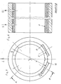
- FIG. 1 shows in cross section a hydrodynamic, completely round radial sliding bearing with a completely surrounding sliding surface, which consists of an elastomer sliding shell 1. This is supported on a support bearing shell 2. It is a radial slide bearing with a single constant load direction L. Symmetrical to this load direction are in the bearing zone of the Bearing in the elastomer sliding shell 1 two sections 3 are provided with a reduced material cross section of the elastomer sliding shell 1. This reduction in the material cross section is shown in the drawing as offset a. The reduced material cross section results from a corresponding projection 4 of the support bearing shell 2. The support surface 5 of these two projections 4 each forms an arcuate section with a radius R.
- a lubricating groove 6 running in the axial direction is arranged between the two sections 3 of smaller material cross section.
- Figure 2 shows two lubricating fluid holes 7 through which lubricating fluid, preferably water, is introduced into the bearing.
- FIGS. 3 and 4 correspond to those of FIGS. 1 and 2, only one being inserted into the bearing; Wave 8 is located.
- M L indicates the center of the bearing and M W the center of the shaft. Again, only a single load direction L is provided. In the area of the two sections 3 of smaller material cross-section, the two pressure peaks 9 shown are formed.
- the radius R forming the support surfaces 5 of the two projections 4 is approximately 1 to 1.4 times the diameter D of the shaft 8.
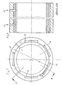
- FIG. 5 can also be transferred to a radial slide bearing with an undetermined or changing load direction.
- a proposed solution is shown in FIGS. 7 and 8.
- FIG. 9 corresponds to the embodiment according to FIG. 7 with regard to the bearing load.
- the sections 3 of reduced cross-section within the elastomer sliding shell 1 are in turn formed by projections 4 of the support bearing shell 2, but these projections 4 are undercut and thus have a fixed shape Ensure connection with the elastomer sliding shell 1.
- the elastomer sliding shell 1 is composed together with the support bearing shell 2 from prefabricated bearing segments 11, which can be fixed in position by screws 12. This construction is particularly suitable for large water turbines as a shaft guide bearing or as an impeller split ring bearing.
Landscapes
- Engineering & Computer Science (AREA)
- General Engineering & Computer Science (AREA)
- Mechanical Engineering (AREA)
- Sliding-Contact Bearings (AREA)
- Support Of The Bearing (AREA)
- Structures Of Non-Positive Displacement Pumps (AREA)
Priority Applications (1)
| Application Number | Priority Date | Filing Date | Title |
|---|---|---|---|
| AT85112442T ATE50328T1 (de) | 1985-01-19 | 1985-10-02 | Radialgleitlager. |
Applications Claiming Priority (2)
| Application Number | Priority Date | Filing Date | Title |
|---|---|---|---|
| DE3501731 | 1985-01-19 | ||
| DE19853501731 DE3501731A1 (de) | 1985-01-19 | 1985-01-19 | Radialgleitlager |
Publications (3)
| Publication Number | Publication Date |
|---|---|
| EP0188664A2 true EP0188664A2 (fr) | 1986-07-30 |
| EP0188664A3 EP0188664A3 (en) | 1987-05-06 |
| EP0188664B1 EP0188664B1 (fr) | 1990-02-07 |
Family
ID=6260259
Family Applications (1)
| Application Number | Title | Priority Date | Filing Date |
|---|---|---|---|
| EP85112442A Expired - Lifetime EP0188664B1 (fr) | 1985-01-19 | 1985-10-02 | Palier lisse radial |
Country Status (3)
| Country | Link |
|---|---|
| EP (1) | EP0188664B1 (fr) |
| AT (1) | ATE50328T1 (fr) |
| DE (2) | DE3501731A1 (fr) |
Cited By (4)
| Publication number | Priority date | Publication date | Assignee | Title |
|---|---|---|---|---|
| FR2656673A1 (fr) * | 1989-12-28 | 1991-07-05 | Renault Automation | Perfectionnements aux machines d'usinage a broche ou outil rotatif. |
| US5560714A (en) * | 1994-09-21 | 1996-10-01 | Rolls-Royce Power Engineering, Plc | Bearing Assembly |
| US6238093B1 (en) | 1997-04-17 | 2001-05-29 | Duramax Marine, Llc | Partial arc bearing assembly and method of making the same |
| CN103307432A (zh) * | 2013-05-23 | 2013-09-18 | 吴江市信合织造有限公司 | 一种辊轴润滑结构 |
Families Citing this family (6)
| Publication number | Priority date | Publication date | Assignee | Title |
|---|---|---|---|---|
| DE3635203C1 (de) * | 1986-10-16 | 1988-03-24 | Voith Gmbh J M | Leitschaufellagerung fuer Wasserturbinen |
| WO2014156548A1 (fr) | 2013-03-29 | 2014-10-02 | カヤバ工業株式会社 | Machine rotative à pression de liquide |
| US10400821B2 (en) * | 2015-08-19 | 2019-09-03 | Daido Metal Company Ltd. | Vertical bearing device |
| KR102010445B1 (ko) * | 2015-08-19 | 2019-08-13 | 다이도 메탈 고교 가부시키가이샤 | 수직형 베어링 장치 |
| DE102016215943A1 (de) * | 2016-08-25 | 2018-03-01 | Zf Friedrichshafen Ag | Verformungsoptimiertes Gleitlager |
| DE102018206905B4 (de) | 2018-05-04 | 2022-11-10 | Zf Friedrichshafen Ag | Schmierstoffversorgung eines Radialgleitlagers |
Family Cites Families (5)
| Publication number | Priority date | Publication date | Assignee | Title |
|---|---|---|---|---|
| CA742601A (en) * | 1966-09-13 | W. Galuska Charles | Filtered water lubricating system for propeller shaft bearing | |
| GB1183045A (en) * | 1966-04-07 | 1970-03-04 | Glacier Co Ltd | Improvements in or relating to Bearings |
| FR1485799A (fr) * | 1966-06-08 | 1967-06-23 | Metalastik Ltd | Perfectionnements aux coussinets élastiques |
| GB1175470A (en) * | 1968-08-23 | 1969-12-23 | Ford Motor Co | Spring Loaded Bearing |
| GB1517160A (en) * | 1975-11-24 | 1978-07-12 | Atomic Energy Authority Uk | Gas bearings |
-
1985
- 1985-01-19 DE DE19853501731 patent/DE3501731A1/de active Granted
- 1985-10-02 DE DE8585112442T patent/DE3575984D1/de not_active Expired - Fee Related
- 1985-10-02 AT AT85112442T patent/ATE50328T1/de not_active IP Right Cessation
- 1985-10-02 EP EP85112442A patent/EP0188664B1/fr not_active Expired - Lifetime
Cited By (7)
| Publication number | Priority date | Publication date | Assignee | Title |
|---|---|---|---|---|
| FR2656673A1 (fr) * | 1989-12-28 | 1991-07-05 | Renault Automation | Perfectionnements aux machines d'usinage a broche ou outil rotatif. |
| EP0436427A1 (fr) * | 1989-12-28 | 1991-07-10 | Renault-Automation | Perfectionnement aux machines d'usinage à broche ou outil rotatif |
| US5560714A (en) * | 1994-09-21 | 1996-10-01 | Rolls-Royce Power Engineering, Plc | Bearing Assembly |
| US6406184B2 (en) | 1996-04-18 | 2002-06-18 | Duramax Marine, Llc | Partial arc bearing slab |
| US6238093B1 (en) | 1997-04-17 | 2001-05-29 | Duramax Marine, Llc | Partial arc bearing assembly and method of making the same |
| CN103307432A (zh) * | 2013-05-23 | 2013-09-18 | 吴江市信合织造有限公司 | 一种辊轴润滑结构 |
| CN103307432B (zh) * | 2013-05-23 | 2015-07-29 | 江苏银桥纺织科技有限公司 | 一种辊轴润滑结构 |
Also Published As
| Publication number | Publication date |
|---|---|
| DE3501731A1 (de) | 1986-07-24 |
| EP0188664A3 (en) | 1987-05-06 |
| DE3501731C2 (fr) | 1988-09-22 |
| EP0188664B1 (fr) | 1990-02-07 |
| DE3575984D1 (de) | 1990-03-15 |
| ATE50328T1 (de) | 1990-02-15 |
Similar Documents
| Publication | Publication Date | Title |
|---|---|---|
| DE1525190C3 (de) | Selbstdruckerzeugendes Axialgleitlager | |
| DE69007079T2 (de) | Buchse für Ölfilmlager. | |
| EP0753678B1 (fr) | Palier à contact lisse pour un arbre | |
| DE3739053A1 (de) | Hydrostatisches gleitlager | |
| EP2721313B1 (fr) | Palier lisse | |
| DE3247948A1 (de) | Kaefig fuer kugellager, insbesondere fuer schraegkugellager | |
| DE69404658T2 (de) | Verriegelte dichtung und hülse für ölfillmlager eines walzwerkes | |
| EP0188664A2 (fr) | Palier lisse radial | |
| DE2345487C2 (de) | Schleifende Dichtung für Pendelwälzlager | |
| DE2529473C3 (de) | Gleitschuhanordnung, insbesondere für Axial- und Radialkolbenmaschinen | |
| DE2118077A1 (de) | Fluidlager hoher Tragfähigkeit | |
| DE19804734A1 (de) | Planetenscheibe | |
| DE1813676A1 (de) | Anordnung in Pumpen | |
| DE3406963C2 (de) | In der Axialrichtung geteiltes Lagergehäuse mit einer Ölförderschmierung | |
| EP1678425A1 (fr) | Roulement a billes | |
| DE3140017A1 (de) | Axiale hydrodynamische gleitlagerung | |
| DE102012016983B4 (de) | Wälzlager mit Wälzlagerkäfig | |
| DE2210979C3 (de) | Spiralrillengleitlager | |
| DE69402507T2 (de) | Pendelrollenlager | |
| DE1575375A1 (de) | Dynamisch-statisches Gleitringlager fuer Axial- und Radialbelastung | |
| DE4217268C2 (de) | Hydrodynamisch wirksames kombiniertes Radial-Axialgleitlager | |
| DE2331412A1 (de) | Abdichtanordnung fuer zwei relativ zueinander drehende maschinenteile | |
| DE102022106927A1 (de) | Kegelrollenlager und -anordnung | |
| DE3904718A1 (de) | Schwimmende drallschneidendichtung | |
| DE3902937C2 (de) | Changierlager |
Legal Events
| Date | Code | Title | Description |
|---|---|---|---|
| PUAI | Public reference made under article 153(3) epc to a published international application that has entered the european phase |
Free format text: ORIGINAL CODE: 0009012 |
|
| AK | Designated contracting states |
Kind code of ref document: A2 Designated state(s): AT BE CH DE FR GB IT LI LU NL SE |
|
| PUAL | Search report despatched |
Free format text: ORIGINAL CODE: 0009013 |
|
| AK | Designated contracting states |
Kind code of ref document: A3 Designated state(s): AT BE CH DE FR GB IT LI LU NL SE |
|
| 17P | Request for examination filed |
Effective date: 19870827 |
|
| 17Q | First examination report despatched |
Effective date: 19880701 |
|
| GRAA | (expected) grant |
Free format text: ORIGINAL CODE: 0009210 |
|
| AK | Designated contracting states |
Kind code of ref document: B1 Designated state(s): AT BE CH DE FR GB IT LI LU NL SE |
|
| REF | Corresponds to: |
Ref document number: 50328 Country of ref document: AT Date of ref document: 19900215 Kind code of ref document: T |
|
| REF | Corresponds to: |
Ref document number: 3575984 Country of ref document: DE Date of ref document: 19900315 |
|
| GBT | Gb: translation of ep patent filed (gb section 77(6)(a)/1977) | ||
| ITF | It: translation for a ep patent filed | ||
| ET | Fr: translation filed | ||
| PLBE | No opposition filed within time limit |
Free format text: ORIGINAL CODE: 0009261 |
|
| STAA | Information on the status of an ep patent application or granted ep patent |
Free format text: STATUS: NO OPPOSITION FILED WITHIN TIME LIMIT |
|
| 26N | No opposition filed | ||
| PGFP | Annual fee paid to national office [announced via postgrant information from national office to epo] |
Ref country code: LU Payment date: 19910926 Year of fee payment: 7 |
|
| ITTA | It: last paid annual fee | ||
| EPTA | Lu: last paid annual fee | ||
| PG25 | Lapsed in a contracting state [announced via postgrant information from national office to epo] |
Ref country code: LU Free format text: LAPSE BECAUSE OF NON-PAYMENT OF DUE FEES Effective date: 19921002 |
|
| EAL | Se: european patent in force in sweden |
Ref document number: 85112442.0 |
|
| PGFP | Annual fee paid to national office [announced via postgrant information from national office to epo] |
Ref country code: GB Payment date: 19970930 Year of fee payment: 13 |
|
| PGFP | Annual fee paid to national office [announced via postgrant information from national office to epo] |
Ref country code: SE Payment date: 19971002 Year of fee payment: 13 |
|
| PGFP | Annual fee paid to national office [announced via postgrant information from national office to epo] |
Ref country code: FR Payment date: 19971024 Year of fee payment: 13 |
|
| PGFP | Annual fee paid to national office [announced via postgrant information from national office to epo] |
Ref country code: BE Payment date: 19971028 Year of fee payment: 13 |
|
| PGFP | Annual fee paid to national office [announced via postgrant information from national office to epo] |
Ref country code: CH Payment date: 19971029 Year of fee payment: 13 |
|
| PGFP | Annual fee paid to national office [announced via postgrant information from national office to epo] |
Ref country code: AT Payment date: 19971030 Year of fee payment: 13 |
|
| PGFP | Annual fee paid to national office [announced via postgrant information from national office to epo] |
Ref country code: NL Payment date: 19971031 Year of fee payment: 13 |
|
| PG25 | Lapsed in a contracting state [announced via postgrant information from national office to epo] |
Ref country code: GB Free format text: LAPSE BECAUSE OF NON-PAYMENT OF DUE FEES Effective date: 19981002 Ref country code: AT Free format text: LAPSE BECAUSE OF NON-PAYMENT OF DUE FEES Effective date: 19981002 |
|
| PG25 | Lapsed in a contracting state [announced via postgrant information from national office to epo] |
Ref country code: SE Free format text: LAPSE BECAUSE OF NON-PAYMENT OF DUE FEES Effective date: 19981003 |
|
| PG25 | Lapsed in a contracting state [announced via postgrant information from national office to epo] |
Ref country code: LI Free format text: LAPSE BECAUSE OF NON-PAYMENT OF DUE FEES Effective date: 19981031 Ref country code: CH Free format text: LAPSE BECAUSE OF NON-PAYMENT OF DUE FEES Effective date: 19981031 Ref country code: BE Free format text: LAPSE BECAUSE OF NON-PAYMENT OF DUE FEES Effective date: 19981031 |
|
| PGFP | Annual fee paid to national office [announced via postgrant information from national office to epo] |
Ref country code: DE Payment date: 19990407 Year of fee payment: 14 |
|
| BERE | Be: lapsed |
Owner name: KUNSTSTOFFTECHNIK RODENBERG G.M.B.H. & CO. K.G. Effective date: 19981031 |
|
| PG25 | Lapsed in a contracting state [announced via postgrant information from national office to epo] |
Ref country code: NL Free format text: LAPSE BECAUSE OF NON-PAYMENT OF DUE FEES Effective date: 19990501 |
|
| GBPC | Gb: european patent ceased through non-payment of renewal fee |
Effective date: 19981002 |
|
| REG | Reference to a national code |
Ref country code: CH Ref legal event code: PL |
|
| EUG | Se: european patent has lapsed |
Ref document number: 85112442.0 |
|
| PG25 | Lapsed in a contracting state [announced via postgrant information from national office to epo] |
Ref country code: FR Free format text: LAPSE BECAUSE OF NON-PAYMENT OF DUE FEES Effective date: 19990630 |
|
| NLV4 | Nl: lapsed or anulled due to non-payment of the annual fee |
Effective date: 19990501 |
|
| REG | Reference to a national code |
Ref country code: FR Ref legal event code: ST |
|
| PG25 | Lapsed in a contracting state [announced via postgrant information from national office to epo] |
Ref country code: DE Free format text: LAPSE BECAUSE OF NON-PAYMENT OF DUE FEES Effective date: 20000801 |