EP0188701A2 - Instrument de coagulation bipolaire - Google Patents
Instrument de coagulation bipolaire Download PDFInfo
- Publication number
- EP0188701A2 EP0188701A2 EP85115123A EP85115123A EP0188701A2 EP 0188701 A2 EP0188701 A2 EP 0188701A2 EP 85115123 A EP85115123 A EP 85115123A EP 85115123 A EP85115123 A EP 85115123A EP 0188701 A2 EP0188701 A2 EP 0188701A2
- Authority
- EP
- European Patent Office
- Prior art keywords
- contact
- instrument according
- contacts
- coagulation instrument
- coagulation
- Prior art date
- Legal status (The legal status is an assumption and is not a legal conclusion. Google has not performed a legal analysis and makes no representation as to the accuracy of the status listed.)
- Withdrawn
Links
Images
Classifications
-
- A—HUMAN NECESSITIES
- A61—MEDICAL OR VETERINARY SCIENCE; HYGIENE
- A61B—DIAGNOSIS; SURGERY; IDENTIFICATION
- A61B18/00—Surgical instruments, devices or methods for transferring non-mechanical forms of energy to or from the body
- A61B18/04—Surgical instruments, devices or methods for transferring non-mechanical forms of energy to or from the body by heating
- A61B18/12—Surgical instruments, devices or methods for transferring non-mechanical forms of energy to or from the body by heating by passing a current through the tissue to be heated, e.g. high-frequency current
- A61B18/14—Probes or electrodes therefor
- A61B18/1442—Probes having pivoting end effectors, e.g. forceps
-
- A—HUMAN NECESSITIES
- A61—MEDICAL OR VETERINARY SCIENCE; HYGIENE
- A61B—DIAGNOSIS; SURGERY; IDENTIFICATION
- A61B18/00—Surgical instruments, devices or methods for transferring non-mechanical forms of energy to or from the body
- A61B18/04—Surgical instruments, devices or methods for transferring non-mechanical forms of energy to or from the body by heating
- A61B18/12—Surgical instruments, devices or methods for transferring non-mechanical forms of energy to or from the body by heating by passing a current through the tissue to be heated, e.g. high-frequency current
- A61B18/14—Probes or electrodes therefor
- A61B18/1402—Probes for open surgery
-
- A—HUMAN NECESSITIES
- A61—MEDICAL OR VETERINARY SCIENCE; HYGIENE
- A61B—DIAGNOSIS; SURGERY; IDENTIFICATION
- A61B17/00—Surgical instruments, devices or methods
- A61B2017/0046—Surgical instruments, devices or methods with a releasable handle; with handle and operating part separable
-
- A—HUMAN NECESSITIES
- A61—MEDICAL OR VETERINARY SCIENCE; HYGIENE
- A61B—DIAGNOSIS; SURGERY; IDENTIFICATION
- A61B18/00—Surgical instruments, devices or methods for transferring non-mechanical forms of energy to or from the body
- A61B2018/00053—Mechanical features of the instrument of device
- A61B2018/00059—Material properties
- A61B2018/00071—Electrical conductivity
- A61B2018/00083—Electrical conductivity low, i.e. electrically insulating
-
- A—HUMAN NECESSITIES
- A61—MEDICAL OR VETERINARY SCIENCE; HYGIENE
- A61B—DIAGNOSIS; SURGERY; IDENTIFICATION
- A61B18/00—Surgical instruments, devices or methods for transferring non-mechanical forms of energy to or from the body
- A61B2018/00053—Mechanical features of the instrument of device
- A61B2018/00107—Coatings on the energy applicator
- A61B2018/00136—Coatings on the energy applicator with polymer
Definitions
- the invention relates to a bipolar coagulation instrument with two gripping or clamping legs, which serve as different pole-forming coagulation electrodes, are insulated from one another at least in places of constant mutual contact and are designed for connection to a high-frequency source at the end facing away from their working ends, one of which is the electrical lines is provided by the high-frequency source connector for making contact with the electrodes.
- Such a bipolar coagulation instrument is known as tweezers from DE-PS 30 12 849, in particular for microsurgery.
- the two tweezer legs are designed as gripping legs and are insulated from one another in their mutual fastening area. They are extended to the rear via the fastening point and thus form power connection projections onto which a plug having the power connection cable or electrical lines from the high-frequency source can be plugged in as a connector, as long as this instrument is used.
- bipolar coagulation tweezers Since surgeons have to work quickly and are used to working with tweezers that can be used for grasping tissue parts as well as for preparation and - if necessary - for monopolar coagulation, the known bipolar coagulation tweezers for general surgery and orthopedics have so far not or only been used to a small extent because they have a connection cable. If a surgeon has grasped a bleeding vessel with normal working forceps and brought the bleeding to a standstill, he would have to replace these working forceps for bipolar coagulation forceps with a connecting cable for bipolar coagulation. This would mean that the vessel begins to bleed again and the surgical wound would become confusing due to the bleeding. However, the known bipolar forceps with connection cable are unsuitable as working tweezers because the cable would be annoying and cumbersome when working. The same applies to surgical clamps.
- the bipolar coagulation instrument mentioned at the outset is characterized in that the contacts of the electrodes and that of the connecting piece are designed as contact contacts to be brought together by the user in the contact position.
- the contacts are therefore not form-fitting or clampable connectable contacts with a corresponding coupling of the contacts, as are provided in the bipolar coagulation forceps according to DE-PS 30 12 849 between the power connection projections and the plug, a real plug is avoided.
- bipolar coagulation instrument makes it possible, first of all, to work with the bipolar coagulation instrument in the usual way, grasping or preparing or also holding and clamping, and then to coagulate with the corresponding contact with the connector having the electrical line.
- a simple touch of the contacts does not disturb the position of the instrument and the surgeon, while plugging in a clamping plug in this position would lead to uncontrolled and unwanted movements of the working tips.
- a bipolar coagulation instrument is thus made available which can initially be handled without annoying cables and electrical lines, but then in a selected position due to the existing contacts and their appropriate touch can be used for bipolar coagulation.
- the contacts of the one part to be brought together against the other are provided in a cavity and the contacts of the other part are provided on a projection which fits into the cavity. This gives the opposing poles sufficient guidance when they are brought together in the touch position to enable rapid coagulation.
- the contact cavity is expediently circular in cross section and contains at least two contact springs or similar contact surfaces, preferably opposite one another.
- the contact protrusion of the other part is also expediently circular in cross section, the insulation being on one diameter.
- the insulation of the poles of the contact projection is arranged in the longitudinal direction of the space between the legs or in continuation of their insulation, preferably in one piece with the latter. A single insulating piece can then isolate both the instrument legs and the poles from one another in the contact area.
- the contact cavity of one part can be a hollow cone be formed, which narrows inward from its opening and in the wall area of which the two opposite contact springs or the like. Contact strips are arranged. This simplifies the merging of the two parts to be touched, because a cone with a wide opening can be slipped over the protrusion, but soon moves into the desired contact contact with further movement.
- the contact protrusion of the other part can be a cone or truncated cone that fits the hollow cone.
- the projection of the other part is spherical, it being possible for the ball to be arranged on a neck or stem which is preferably circular in cross section. This enables the part having the hollow cone to be brought together at a certain angle, too. which is of considerable advantage in an operation in which an auxiliary person is to make the contact between the connector having the electrical lines from the high-frequency source and the instrument.
- the contact projection on the end of the instrument facing away from the working tips and the hollow cone on a contact pin having the electrical cables. Like. is arranged.
- This pin with its hollow cone can thus be slipped onto the projection of the instrument if coagulation is to be carried out.
- the formation of the ball and cone facilitates touching and also holding in the touch position, because the parts that are coordinated in this way can be brought together and held together well. It is only necessary to exert a certain pressure in the longitudinal direction of the hollow cone.
- An expedient embodiment of the invention can consist in the fact that the two legs, which can be connected with different poles and are insulated from one another, each have one half of the contact projection. In between is the insulation already mentioned.
- the retaining projection can be connected to the legs approximately in a straight extension thereof.
- the contact springs or contact surfaces of the contact cavity are of equal width or - preferably - Narrower than the thickness of the insulation of the contact projection on the outside. This can prevent a contact surface from bridging the insulation if it does not have a spherical shape. Coagulation would then only take place in a single position in which the contact springs happen to lie exactly on the insulation. As already mentioned above, however, it is then sufficient to twist the connecting piece slightly in order to achieve an electrical connection of the two poles and thus coagulation.
- the connector serving as a contact pin can be angled between its handle and the area having the contact cone. This further facilitates handling, in particular if an operator standing to the side of the surgeon is to place this connecting piece on the instrument held by the surgeon.
- the contact pin can have a switch in the area of the handle for interrupting the power supply to the contact cone. In order to achieve the greatest possible security for users, it is advantageous if the contact cone is hidden in the contact pin and embedded insulated.
- bipolar coagulation instrument with which it is possible to work grasping and preparing and also clamping, without being hindered by power cables, but with which bipolar coagulation is nevertheless desirable and advantageous can be without a significant additional operational or handling effort is necessary.
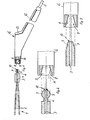
- a pair of tweezers 1 is designed as a bipolar coagulation instrument in that its two legs 2 serve as coagulation electrodes forming different poles and are insulated from one another at the end facing away from their working ends in the area of their mutual contact and attachment.
- the insulation 3 and a holding sleeve 4 as a fastening element can be seen schematically in FIG. 1.
- the insulation 3 can also be seen in the other figures.
- This end region of the tweezers 1 is also designed for connection to a high-frequency source, a connector 6 having the electrical lines 5 from the high-frequency source being provided, with which the contact to the electrodes or tweezer legs 2 for the coagulation process can be established in a manner to be described .
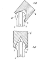
- the contacts 7 of the electrodes 2 and the contacts 8 of the connecting piece 6, which are yet to be described in more detail, are designed as contact contacts to be held together by the user in the contact position (FIGS. 4 and 5 in dashed lines in FIGS. 2 and 3). So there is no detachable, but positive or non-positive or jamming coupling or connection between the contacts 7 and 8, but only a touch connection.
- the formation of the insulation 3 and the attachment 4 at the end of the tweezers 1 can essentially correspond to that of the patent 30 12 849 or other such constructions.
- the contacts 8 of one part, in the exemplary embodiment of the connecting piece 6, are provided in a cavity 9 and the contacts 7 of the other part are provided on a projection 10 which fits into the cavity 9.
- Both the contact cavity 9 and the contact projection 10 are circular in cross section, the insulation 3 in the exemplary embodiment being perpendicular to the diameters of this cross section.
- the insulation 3 of the poles or electrodes 2 of the contact protrusion 10 runs in the longitudinal direction of the space between the legs 2 or in continuation of their insulation and is integral with this and therefore also has the same reference number 3.
- the contact cavity 9 is designed as a hollow cone, which narrows inwards from its opening and in the wall area of which the two contact springs 8 or the like contact strips lying opposite one another are arranged.
- the contact projection 10 can be designed as a cone or truncated cone. According to the remaining figures, however, it is preferably spherical, the ball being arranged on a neck 11 or stem, which is preferably circular in cross section. This allows the significant deviations in the orientation between the two parts to be brought into contact, as indicated in FIGS. 4 and 5, contact being able to be made and coagulation carried out in any orientation.
- the contact projection 10 is arranged at the end of the instrument 1 facing away from the working tips and the hollow cone 9 is arranged on a contact pin having the electrical cables 5, namely the connecting piece 6.
- the connector 6 with its hollow cone 9 can simply be slipped onto the contact ball 10, this slipping on at virtually any angle and in practically any rotational position leading to real contact, thus allowing coagulation, which simplifies handling and favors the working speed.
- the central axis of the connecting piece 6 can deviate from that of the instrument 1 by up to 40 ° on both sides, as is indicated in FIG. 4.
- a particularly simple manufacture of the instrument 1 is obtained if, as in the exemplary embodiment, the two legs 2, which are connected to different poles for the coagulation process and are insulated from one another, each have a half of the contact projection 10 or form one piece.
- the contact projection 10 is connected to the leg 2 approximately in a straight extension thereof, each contact 7 being connected in one piece to its associated instrument leg 2.
- the contact springs 8 or contact surfaces of the contact cavity 9 are the same width or preferably narrower than the thickness of the contact Insulation 3 of the contact projection 10 on the outside thereof. Thus, if the contact surfaces are applied very precisely, it can only result at the insulation 3 that no coagulation takes place. A slight twist of the Connector 6 then leads immediately to the desired contact.
- Fig. 1 it can still be seen that the connector 6 serving as a contact pin is angled between a handle 12 and the area having the contact cone 9. As a result, a person standing to the side of the user of the tweezers 1 can nevertheless bring the connecting piece 6 comfortably and safely into the desired contact contact with the contact projection 10.
- the contact pin 6 has in the area of the handle 12 a switch 13 with which the power supply to the contact cone 9 can be interrupted.
- FIGS. 1 to 3 it is indicated in FIGS. 1 to 3 that the contact cone 9 with the leads 14 to its contacts 8 is covered and insulated in the contact pin 6, so that use is safe for everyone involved.
Landscapes
- Health & Medical Sciences (AREA)
- Surgery (AREA)
- Engineering & Computer Science (AREA)
- Life Sciences & Earth Sciences (AREA)
- Biomedical Technology (AREA)
- Otolaryngology (AREA)
- Nuclear Medicine, Radiotherapy & Molecular Imaging (AREA)
- Plasma & Fusion (AREA)
- Physics & Mathematics (AREA)
- Heart & Thoracic Surgery (AREA)
- Medical Informatics (AREA)
- Molecular Biology (AREA)
- Animal Behavior & Ethology (AREA)
- General Health & Medical Sciences (AREA)
- Public Health (AREA)
- Veterinary Medicine (AREA)
- Surgical Instruments (AREA)
Applications Claiming Priority (2)
| Application Number | Priority Date | Filing Date | Title |
|---|---|---|---|
| DE3501863A DE3501863C2 (de) | 1985-01-22 | 1985-01-22 | Bipolares Koagulationsinstrument |
| DE3501863 | 1985-01-22 |
Publications (2)
| Publication Number | Publication Date |
|---|---|
| EP0188701A2 true EP0188701A2 (fr) | 1986-07-30 |
| EP0188701A3 EP0188701A3 (fr) | 1987-08-12 |
Family
ID=6260353
Family Applications (1)
| Application Number | Title | Priority Date | Filing Date |
|---|---|---|---|
| EP85115123A Withdrawn EP0188701A3 (fr) | 1985-01-22 | 1985-11-28 | Instrument de coagulation bipolaire |
Country Status (3)
| Country | Link |
|---|---|
| US (1) | US4732149A (fr) |
| EP (1) | EP0188701A3 (fr) |
| DE (1) | DE3501863C2 (fr) |
Cited By (2)
| Publication number | Priority date | Publication date | Assignee | Title |
|---|---|---|---|---|
| WO1995020921A1 (fr) * | 1994-02-07 | 1995-08-10 | Andrea Budic | Dispositif de maintien d'instruments chirurgicaux et de commande manuelle de leur alimentation electrique |
| EP0697199A1 (fr) * | 1994-08-18 | 1996-02-21 | Aesculap Ag | Instrument chirurgical bipolaire |
Families Citing this family (49)
| Publication number | Priority date | Publication date | Assignee | Title |
|---|---|---|---|---|
| GB8808950D0 (en) * | 1988-04-15 | 1988-05-18 | Marlin Lighting Ltd | Articulated support for lamp &c |
| US4919131A (en) * | 1988-06-02 | 1990-04-24 | Circon Corporation | Resectoscope with improved guide block and electrical plug connection |
| US4917621A (en) * | 1988-06-02 | 1990-04-17 | Circon Corporation | Resectoscope with improved guide block and electrical plug connection |
| DE3917328A1 (de) * | 1989-05-27 | 1990-11-29 | Wolf Gmbh Richard | Bipolares koagulationsinstrument |
| DE3937700C2 (de) * | 1989-11-13 | 1998-02-19 | Sutter Hermann Select Med Tech | Bipolare Koagulationspinzette mit Schalter |
| DE4113037A1 (de) * | 1991-04-22 | 1992-10-29 | Sutter Hermann Select Med Tech | Bipolares koagulations- und/oder schneidinstrument |
| US5263967B1 (en) * | 1992-05-15 | 2000-12-19 | Brimfield Prec Inc | Medical instrument with dual action drive |
| US5282800A (en) * | 1992-09-18 | 1994-02-01 | Edward Weck, Inc. | Surgical instrument |
| CA2106126A1 (fr) * | 1992-09-23 | 1994-03-24 | Ian M. Scott | Instruments chirurgicaux bipolaires |
| CA2121194A1 (fr) * | 1993-05-06 | 1994-11-07 | Corbett Stone | Instruments electrochirurgicaux bipolaires |
| USD358887S (en) | 1993-12-02 | 1995-05-30 | Cobot Medical Corporation | Combined cutting and coagulating forceps |
| US5573535A (en) * | 1994-09-23 | 1996-11-12 | United States Surgical Corporation | Bipolar surgical instrument for coagulation and cutting |
| US5814043A (en) | 1996-09-06 | 1998-09-29 | Mentor Ophthalmics, Inc. | Bipolar electrosurgical device |
| US5947996A (en) * | 1997-06-23 | 1999-09-07 | Medicor Corporation | Yoke for surgical instrument |
| US6096037A (en) | 1997-07-29 | 2000-08-01 | Medtronic, Inc. | Tissue sealing electrosurgery device and methods of sealing tissue |
| GB9823490D0 (en) | 1998-10-28 | 1998-12-23 | Uniplex U K Limited | Bipolar forceps |
| US6447443B1 (en) * | 2001-01-13 | 2002-09-10 | Medtronic, Inc. | Method for organ positioning and stabilization |
| US6554636B2 (en) * | 2000-04-06 | 2003-04-29 | Tronic Limited | Connector apparatus |
| US20020107514A1 (en) | 2000-04-27 | 2002-08-08 | Hooven Michael D. | Transmural ablation device with parallel jaws |
| US6546935B2 (en) | 2000-04-27 | 2003-04-15 | Atricure, Inc. | Method for transmural ablation |
| US6905498B2 (en) | 2000-04-27 | 2005-06-14 | Atricure Inc. | Transmural ablation device with EKG sensor and pacing electrode |
| US6932811B2 (en) * | 2000-04-27 | 2005-08-23 | Atricure, Inc. | Transmural ablation device with integral EKG sensor |
| US7740623B2 (en) | 2001-01-13 | 2010-06-22 | Medtronic, Inc. | Devices and methods for interstitial injection of biologic agents into tissue |
| US20040138621A1 (en) * | 2003-01-14 | 2004-07-15 | Jahns Scott E. | Devices and methods for interstitial injection of biologic agents into tissue |
| US7628780B2 (en) | 2001-01-13 | 2009-12-08 | Medtronic, Inc. | Devices and methods for interstitial injection of biologic agents into tissue |
| US7967816B2 (en) | 2002-01-25 | 2011-06-28 | Medtronic, Inc. | Fluid-assisted electrosurgical instrument with shapeable electrode |
| US7291161B2 (en) | 2002-10-02 | 2007-11-06 | Atricure, Inc. | Articulated clamping member |
| FR2851453A1 (fr) * | 2003-02-26 | 2004-08-27 | 7 Med Ind | Pince bipolaire pour coagulation chirurgicale, et ensemble de coagulation chirurgicale comprenant une telle pince |
| US7288092B2 (en) | 2003-04-23 | 2007-10-30 | Atricure, Inc. | Method and apparatus for ablating cardiac tissue with guide facility |
| US20050187545A1 (en) * | 2004-02-20 | 2005-08-25 | Hooven Michael D. | Magnetic catheter ablation device and method |
| US7530980B2 (en) * | 2004-04-14 | 2009-05-12 | Atricure, Inc | Bipolar transmural ablation method and apparatus |
| EP1750608B1 (fr) * | 2004-06-02 | 2012-10-03 | Medtronic, Inc. | Dispositif d'ablation comprenant des machoires |
| US7645278B2 (en) * | 2006-02-22 | 2010-01-12 | Olympus Corporation | Coagulating cutter |
| US8690864B2 (en) * | 2007-03-09 | 2014-04-08 | Covidien Lp | System and method for controlling tissue treatment |
| US8945117B2 (en) | 2009-02-11 | 2015-02-03 | Boston Scientific Scimed, Inc. | Insulated ablation catheter devices and methods of use |
| US8708211B2 (en) | 2009-02-12 | 2014-04-29 | Covidien Lp | Powered surgical instrument with secondary circuit board |
| EP2448510B1 (fr) | 2009-06-30 | 2016-08-31 | Boston Scientific Scimed, Inc. | Cathéter hybride irrigué ouvert de cartographie et d'ablation |
| US8968358B2 (en) * | 2009-08-05 | 2015-03-03 | Covidien Lp | Blunt tissue dissection surgical instrument jaw designs |
| JP6117209B2 (ja) | 2011-09-14 | 2017-04-19 | ボストン サイエンティフィック サイムド,インコーポレイテッドBoston Scientific Scimed,Inc. | 複数のアブレーションモードを備えたアブレーション装置及び同アブレーション装置を含むシステム |
| EP2755588B1 (fr) | 2011-09-14 | 2016-05-18 | Boston Scientific Scimed, Inc. | Dispositif d'ablation équipé d'un ballonnet à conductivité ionique |
| CN104039257A (zh) | 2012-01-10 | 2014-09-10 | 波士顿科学医学有限公司 | 电生理学系统 |
| JP5830614B2 (ja) | 2012-01-31 | 2015-12-09 | ボストン サイエンティフィック サイムド,インコーポレイテッドBoston Scientific Scimed,Inc. | 超音波組織撮像のための流体に基づいた音響結合を有するアブレーションプローブ、および、アブレーションおよび超音波撮像システム |
| US20140073893A1 (en) * | 2012-09-12 | 2014-03-13 | Boston Scientific Scimed Inc. | Open irrigated-mapping linear ablation catheter |
| EP2897544B1 (fr) | 2012-09-18 | 2018-12-12 | Boston Scientific Scimed, Inc. | Cartographie et ablation à l'aide d'un cathéter d'ablation refroidi en boucle fermée |
| WO2014047071A1 (fr) | 2012-09-18 | 2014-03-27 | Boston Scientific Scimed, Inc. | Cartographie et retrait de cathéter d'ablation refroidi à boucle fermée ayant une pointe plate |
| US10524684B2 (en) | 2014-10-13 | 2020-01-07 | Boston Scientific Scimed Inc | Tissue diagnosis and treatment using mini-electrodes |
| EP4316361A3 (fr) | 2014-10-24 | 2024-05-01 | Boston Scientific Scimed Inc. | Dispositifs médicaux dotés d'un ensemble d'électrode souple couplé à une pointe d'ablation |
| US9743854B2 (en) | 2014-12-18 | 2017-08-29 | Boston Scientific Scimed, Inc. | Real-time morphology analysis for lesion assessment |
| RU206775U1 (ru) * | 2020-12-15 | 2021-09-28 | Федеральное государственное бюджетное образовательное учреждение высшего образования "Саратовский государственный технический университет имени Гагарина Ю.А." (СГТУ имени Гагарина Ю.А.) | Электрод для электрокоагуляции биологических тканей |
Family Cites Families (14)
| Publication number | Priority date | Publication date | Assignee | Title |
|---|---|---|---|---|
| US1071978A (en) * | 1912-04-11 | 1913-09-02 | John E White | Device for removing hairs. |
| US1650014A (en) * | 1920-11-01 | 1927-11-22 | Albert R Goldrick | Electrical swivel connecter |
| DE499737C (de) * | 1928-08-21 | 1930-06-13 | Georg Reittinger | Gelenkverbindung fuer elektrische Leitungen |
| GB381354A (en) * | 1931-10-26 | 1932-10-06 | Macintosh Cable Company Ltd | An improved electrical joint, coupling or connection |
| US1945327A (en) * | 1932-06-30 | 1934-01-30 | Willis B Morse | Combined tongue depressor and electrode for electrocoagulation of tonsils |
| US3322124A (en) * | 1964-11-25 | 1967-05-30 | Donald W Ireland | Method and apparatus for retrieving metallic objects from teeth, flesh, bone and thelike |
| US3643663A (en) * | 1968-10-16 | 1972-02-22 | F L Fischer | Coagulating instrument |
| US3752160A (en) * | 1971-07-15 | 1973-08-14 | Sybron Corp | Disposable electrode switch |
| CA1018419A (fr) * | 1973-07-04 | 1977-10-04 | Gerald Turp | Instrument pour la cauterisation des trompes |
| US4033351A (en) * | 1974-06-14 | 1977-07-05 | Siemens Aktiengesellschaft | Bipolar cutting electrode for high-frequency surgery |
| DE2639956C3 (de) * | 1976-09-04 | 1987-04-16 | Erbe Elektromedizin GmbH, 7400 Tübingen | Pinzette für bipolare Koagulationen |
| DE3012849C2 (de) * | 1980-04-02 | 1982-04-29 | Holzhauer + Sutter medizinisch-technische Geräte und Instrumente, GmbH, 7800 Freiburg | Bipolare Koagulationspinzette |
| CA1192465A (fr) * | 1981-03-11 | 1985-08-27 | Edward A. Lottick | Electrocautere a commutateur amovible |
| DE3110666C2 (de) * | 1981-03-19 | 1984-08-30 | Holzhauer + Sutter medizinisch-technische Geräte und Instrumente, GmbH, 7800 Freiburg | Pinzette für die Mikro-Chirurgie |
-
1985
- 1985-01-22 DE DE3501863A patent/DE3501863C2/de not_active Expired
- 1985-11-28 EP EP85115123A patent/EP0188701A3/fr not_active Withdrawn
-
1987
- 1987-01-21 US US07/008,043 patent/US4732149A/en not_active Expired - Fee Related
Cited By (2)
| Publication number | Priority date | Publication date | Assignee | Title |
|---|---|---|---|---|
| WO1995020921A1 (fr) * | 1994-02-07 | 1995-08-10 | Andrea Budic | Dispositif de maintien d'instruments chirurgicaux et de commande manuelle de leur alimentation electrique |
| EP0697199A1 (fr) * | 1994-08-18 | 1996-02-21 | Aesculap Ag | Instrument chirurgical bipolaire |
Also Published As
| Publication number | Publication date |
|---|---|
| US4732149A (en) | 1988-03-22 |
| DE3501863A1 (de) | 1986-07-24 |
| EP0188701A3 (fr) | 1987-08-12 |
| DE3501863C2 (de) | 1987-02-19 |
Similar Documents
| Publication | Publication Date | Title |
|---|---|---|
| DE3501863C2 (de) | Bipolares Koagulationsinstrument | |
| DE69803141T2 (de) | Verfahren und Einrichtung zur Versorgung von medizinischen Geräten mit elektrischer Energie | |
| DE3490633C2 (de) | Bipolares elektrochirurgisches Instrument | |
| DE69119177T2 (de) | Elektrochirurgische laparoskopische Kauterisationselektrode | |
| EP1336384B1 (fr) | Instrument medical bipolaire pour couper des tissues | |
| DE69633101T2 (de) | Automatischer Messerschutz für chirurgische Instrumente mit gekrümmten Backen | |
| DE69823862T2 (de) | Biopolares elektrochirurgisches laparoskopieinstrument | |
| DE69835763T2 (de) | Bipolares elektrochirurgisches instrument mit austauschbarer elektrode | |
| DE69826368T2 (de) | Kapazitiv angekoppeltes, schnurloses, elektrochirurgisches Instrument | |
| DE69833505T2 (de) | Bipolares elektrochirurgisches instrument zum verschliessen von gefässen | |
| DE60017272T2 (de) | Elektrochirurgisches koagulationsschneideinstrument | |
| DE69925854T2 (de) | Endoskopische bipolare elektrochirurgische zange | |
| EP1056409B1 (fr) | Instrument bipolaire a usage medical | |
| DE60316052T2 (de) | Elektrochirurgisches Instrument mit Lichtmonitor auf Greifarm | |
| DE69819972T2 (de) | Induktiv angekoppeltes elektrochirurgisches Instrument | |
| DE60113269T3 (de) | Bipolare elektrochirurgische zange mit nichtleitenden abstandhaltern | |
| EP0871405B1 (fr) | Instrument chirurgical bipolaire a haute frequence | |
| DE69828336T2 (de) | Elektrochirurgischer Trokar mit induktivem Adapter | |
| DE4113037A1 (de) | Bipolares koagulations- und/oder schneidinstrument | |
| DE2627679A1 (de) | Blutstillende hochfrequenz-sezierpinzette | |
| WO2001022896A1 (fr) | Instrument medical bipolaire servant a couper des tissus | |
| DE3612646A1 (de) | Elektrochirurgisches griffstueck fuer klingen, nadeln und pinzetten | |
| DE4414807A1 (de) | Elektrochirurgisches Instrument zur Therapie von Varizen | |
| DE2432507A1 (de) | Instrument zur laparoskopischen tubaren kauterisation | |
| WO2004045436A1 (fr) | Dispositif electrochirurgical et procede pour faire fonctionner ce dispositif |
Legal Events
| Date | Code | Title | Description |
|---|---|---|---|
| PUAI | Public reference made under article 153(3) epc to a published international application that has entered the european phase |
Free format text: ORIGINAL CODE: 0009012 |
|
| AK | Designated contracting states |
Kind code of ref document: A2 Designated state(s): AT CH DE FR GB IT LI |
|
| PUAL | Search report despatched |
Free format text: ORIGINAL CODE: 0009013 |
|
| AK | Designated contracting states |
Kind code of ref document: A3 Designated state(s): AT CH DE FR GB IT LI |
|
| STAA | Information on the status of an ep patent application or granted ep patent |
Free format text: STATUS: THE APPLICATION IS DEEMED TO BE WITHDRAWN |
|
| 18D | Application deemed to be withdrawn |
Effective date: 19880215 |